Abstract
The shift towards remote access and control of equipment has become more prominent, especially due to COVID-19 lockdowns. Access to physical/real equipment for practical learning remains important for engineering studies. Thus, this paper presents an approach for remotely accessing and controlling automation equipment for engineering practical activities. Specifically, it addresses the issue of accessing and controlling machines for programmable logic controller (PLC) programming tasks. The combination of a scheduler, remote desktop access, graphical user interface, and a micro-controller allows students to work remotely on practical equipment. The lab computer can be accessed via a remote computer to select one of multiple equipment for practical activities. A prototype system was constructed as proof of concept. The prototype system functions as required.
1. Introduction
The highly dynamic environment of higher education has presented a range of challenges and opportunities. Some of these challenges and opportunities have arisen due to limitations of facilities and resources in educational institutions. Recently, the COVID-19 pandemic has also necessitated physical distancing and remote learning in many countries around the globe. Blended and online delivery of courses has become increasingly relevant during lockdown and physical distancing scenarios. Delivering and managing online and digital learning has been a crucial part of blended/online courses. In this respect, technology has become a powerful tool to develop educational systems. The internet has become a powerful tool for business innovation and positive change in education.
While many course learning materials and activities are made available online [1,2,3], executing practical assessments with physical equipment can be challenging. Often it is easier to conduct these practical assessments in the traditional way, requiring the students to be physically present with the equipment. In face-to-face learning, students often require additional time to complete their practical activities outside the scheduled class times. Classroom access and lab/equipment availability are the main challenges faced, especially in shared learning spaces. A solution to this problem is to allow the students to complete their practical work off-campus by providing a remote access to the on-campus lab equipment. The internet plays a crucial role in enabling the remote access. This concept can be used to support distance learning and thus to enable the students to remotely perform and monitor their practical work.
A review of contemporary virtual and remote laboratory implementations is presented in [4]. According to the authors, a virtual lab uses programs to simulate laboratory environments where students access and conduct experiments in a virtual space. On the other hand, a remote lab is where experiments are located physically away from the experimenter, and the experiments are conducted in a real physical environment. The authors’ review and analysis confirm the advantages of virtual and remote laboratories such as 24 × 7 access, flexibility and freedom of learning pace, and reset/retrial without resource wastage. Several implementations are reviewed, including virtual and remote laboratories for programming robots [5], Virtual Instrument Systems in Reality (VISIR) for engineering [6], and VPLab for virtual programming to develop computer programming knowledge and skills [7]. There were no reviews on remote laboratories for programming PLC controlled devices in real physical environments.
Maiti et al. [8] discuss Remote Access Laboratories (RALs) and Remote Laboratory Management Systems (RLMSs) for distributed remote labs. Remote Access Laboratories have been used to establish experimental expertise on practical engineering topics. Distributed remote laboratories aim to share experiment through a distributed architecture between institutions and individuals. Experiments from various fields are combined as part of a greater system. Remote Laboratory Management Systems (RLMSs) integrate experiments using multiple control strategies. When incorporating an existing experiment into a new distributed RAL system, analysing the experiment with respect to its host or new RLMS is useful in deciding the best methods for inclusion. They propose a framework called SHASS (Software, Hardware, Assessment, Support, and Share-ability) for such evaluation based on experiment properties.
The development of a distance learning system using virtual reality and augmented technologies is discussed in [9]. Two research directions considered are: use of augmented reality applications in the development of e-labs for undergraduate students, master’s students, and researchers; and learning systems and simulation of robotic systems based on movements in a virtual reality environment, respectively. Developing the e-lab programme required the configuration of sensors and the development of a communication network. The remotely controlled robot system is a 5-axis Mitsubishi RV-M1 Move master which uses a CCD camera for remote-control observation. A computer determines each object’s position and orientation, and then the human operator sets the order of robot operations.
Internet web-based laboratories that enable remote operation of experiments used for training in undergraduate engineering courses have been implemented in [10]. This implementation uses LabVIEW software to perform remote control and monitoring of laboratory equipment. The approach is beneficial for developing countries where resources can be shared through the internet. A disadvantage is the cost associated with purchasing and utilising National Instruments data acquisition (DAQ) boards and LabVIEW software. The experiments described in the paper use LabVIEW virtual instruments as the controllers for electropneumatic and electromechanical systems. This would be an unnecessary additional layer of control and cost for the PLC-controlled devices requiring remote access in this research.
The development of a remote lab with two user interfaces for teaching programming and robotics using Arduino boards is presented in [11]. One of the interfaces is based on visual programming while the other interface is similar to the original Arduino textual programming language. Access to the Arduino lab can be made via a mobile application or web browsers. The authors claim their implementation is suitable for courses in institutions with limited resources. While the implementation focuses on low-cost, it is primarily developed for teaching Arduino micro-controller programming, not PLC programming.
A concept for remote programming, configuration, and monitoring for the development and testing of embedded devices is presented in [12]. Basic proof-of-concept functionality has been achieved allowing for easy interaction with remote embedded devices. The authors claim the hardware price of the developed prototype was lower than commercial solutions. However, no numerical values were provided. Another embedded systems design remote laboratory system is presented in [13]. Four experiments are connected via USB to a server PC and a remote user accesses the server via the internet. Each experiment has a separate micro-controller, and a web-interface controls them.
Bellmunt et al. [14] present a remote laboratory for PLC programming based on a flexible manufacturing cell. The developed system consists of a separate PLC for each station and an IP camera for observation. The PLCs are connected over the local area network for local control. A router and internet connection are used for remote control. In this system, the stations are dependent on each other, and it is an expensive system since it requires multiple PLCs. This type of system is also set up for network (ethernet) PLC programming. Some PLCs, such as the one in this paper, are set up for USB programming.
While there are other examples of remote virtual PLC-based labs [15,16], the primary focus of this paper is on remote laboratories for programming PLC-controlled physical devices. Other examples similar to [14] include [17,18,19,20]. All these implementations are developed for web-based programming. The system presented in [17] uses a computer as a WebAccess web server to remotely monitor and control a PLC based system. Their emphasis is not on remote learning but on developing advanced PLC programming skills of remote monitoring and control. The design of three web-based automated systems using a client-server software system termed Remote Control System Architecture (RCSA) is presented in [18]. The three systems also have their own associated PLCs, unlike the research presented in this paper, which uses a single PLC due to resource and cost limitations. Using web browsers can be simple and effective for the user as mentioned in [20]. A drawback is that the system developer needs to be proficient in client-server tools such as JavaScript, PHP, ASP.NET, and databases [19,20].
This paper presents the design of a solution for providing access to multiple automation lab equipment remotely. Initial work on the design is presented in [21]. A modified final version of the design that was prototyped and tested is described in this paper. The emphasis of the design is on a low-cost solution that enables students to program and operate PLC-based equipment remotely in a way that is similar to being physically present with the equipment. This involves remotely accessing free software to program PLC that is connected to a computer via a USB cable. Additional software and an embedded system were developed to facilitate the selection of hardware connected to the PLC.
2. Materials and Methods
This section begins with an overview of the system in the form of a block diagram and an operation flowchart. Following this, information about the system components and their integration is presented in detail.
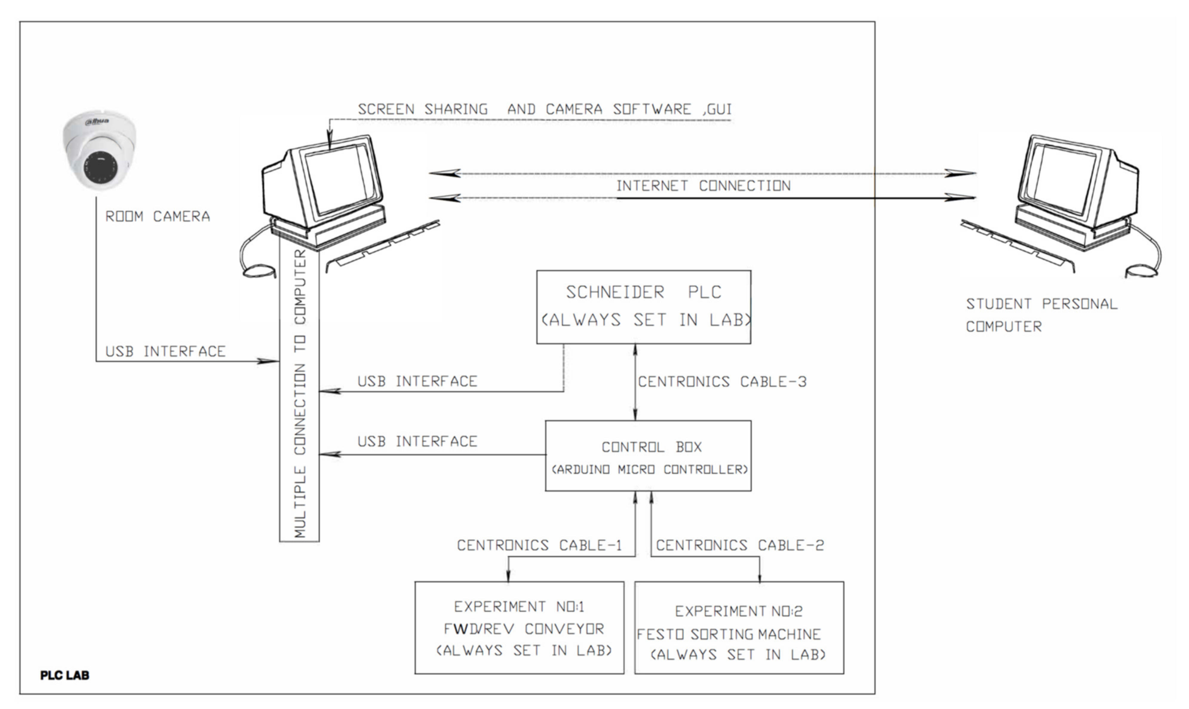
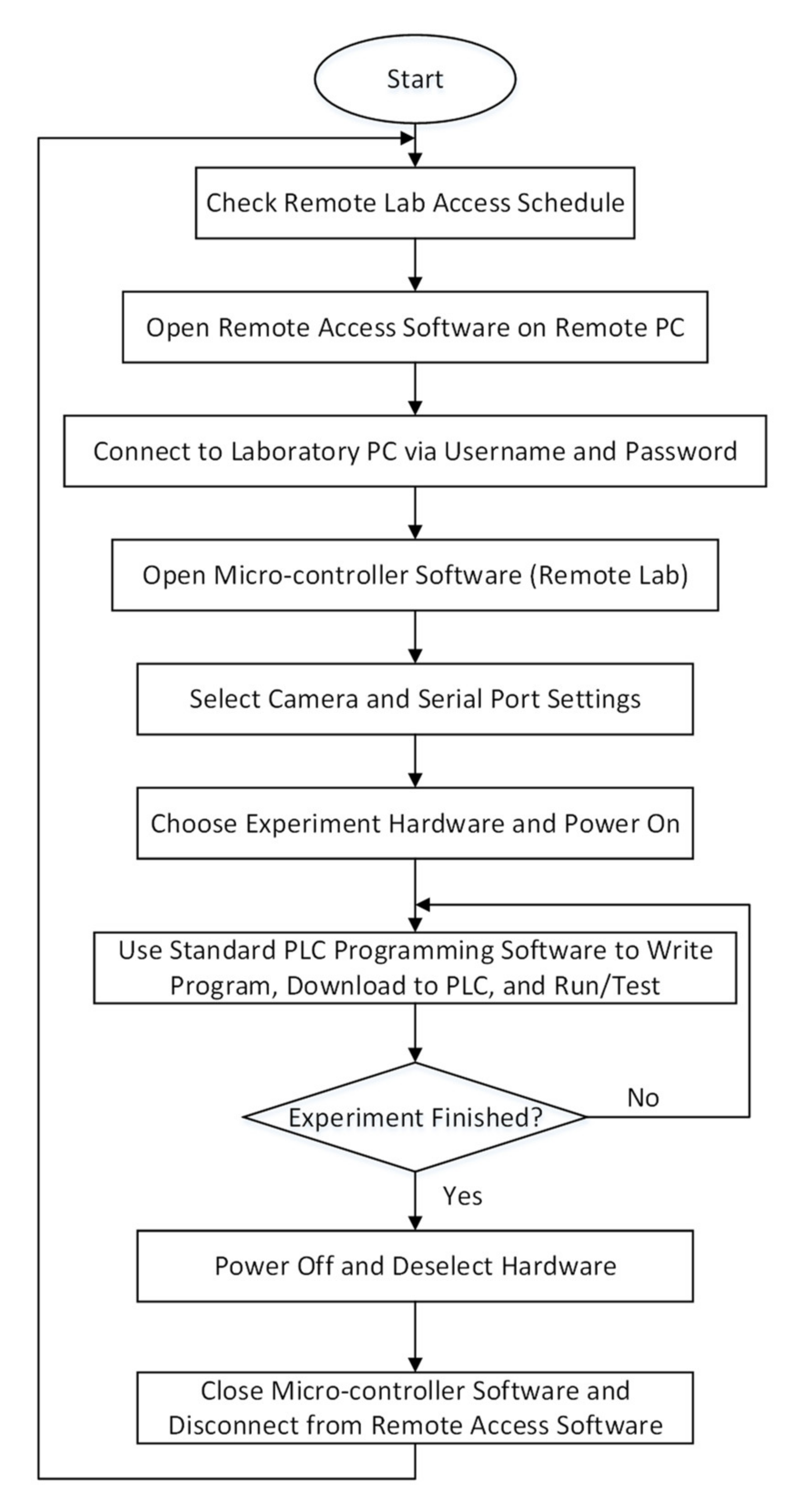
2.1. Overview of System
Figure 1 illustrates a block diagram of the remote laboratory system. A single PLC module (Schneider Compact PLC TM221CE24T [22]) is linked to two hardware equipment: a forward/reverse conveyor system (experiment 1) and a Festo sorting machine (experiment 2).
Figure 1.
Block diagram of the remote laboratory system.
In the original experimental setup, a 24-way Centronics cable directly connected the PLC module to one of the hardware equipment. The cable had to be manually transferred between the hardware equipment. This was subsequently replaced by an intermediate micro-controller that controls the switching between the two hardware. The PLC module, micro-controller, and camera are always connected to a laboratory computer via USB cables. The laboratory computer has the software for programming the PLC module (SoMachine Basic). A remote user can connect to the laboratory computer via a remote desktop connection software to program the PLC module and select the hardware equipment.
The PLC modules are generic and shared between multiple courses and classes on campus (Figure 2). Due to constraints such as limited availability of PLC modules and shared learning spaces, the design utilises a single PLC module to control multiple hardware. The micro-controller serves as a secondary control device to power on/off the hardware and disable the hardware if there is a malfunction on the PLC module. Figure 3 and Figure 4 show the hardware to be connected to the PLC module via the micro-controller.
Figure 2.
Schneider TM221CE24T PLC module.
Figure 3.
Experiment 1 forward/reverse conveyor system.
Figure 4.
Experiment 2 Festo sorting machine.
A simplified flowchart illustrating the procedure for operating the remote laboratory system is shown in Figure 5. Users are required to book time slots for using the system via a remote lab access schedule online document (Figure 6). When it is a user’s turn to use the system, they first open the remote access software on their computer. Next, they connect to the laboratory computer via a username and password. Following this, they need to open the micro-controller software (Remote Lab, refer to Section 3.1) to select the camera and access serial port settings. After selecting an experiment hardware for use, the user can use the standard PLC programming software to write, download, and test programs. Upon completion of the experiment (or time period expiry), the user powers off the hardware, closes the micro-controller software, and disconnects from the laboratory computer.
Figure 5.
Simplified flowchart of the remote laboratory operating procedure.
Figure 6.
Sample of remote lab access schedule.
2.2. System Component Descriptions
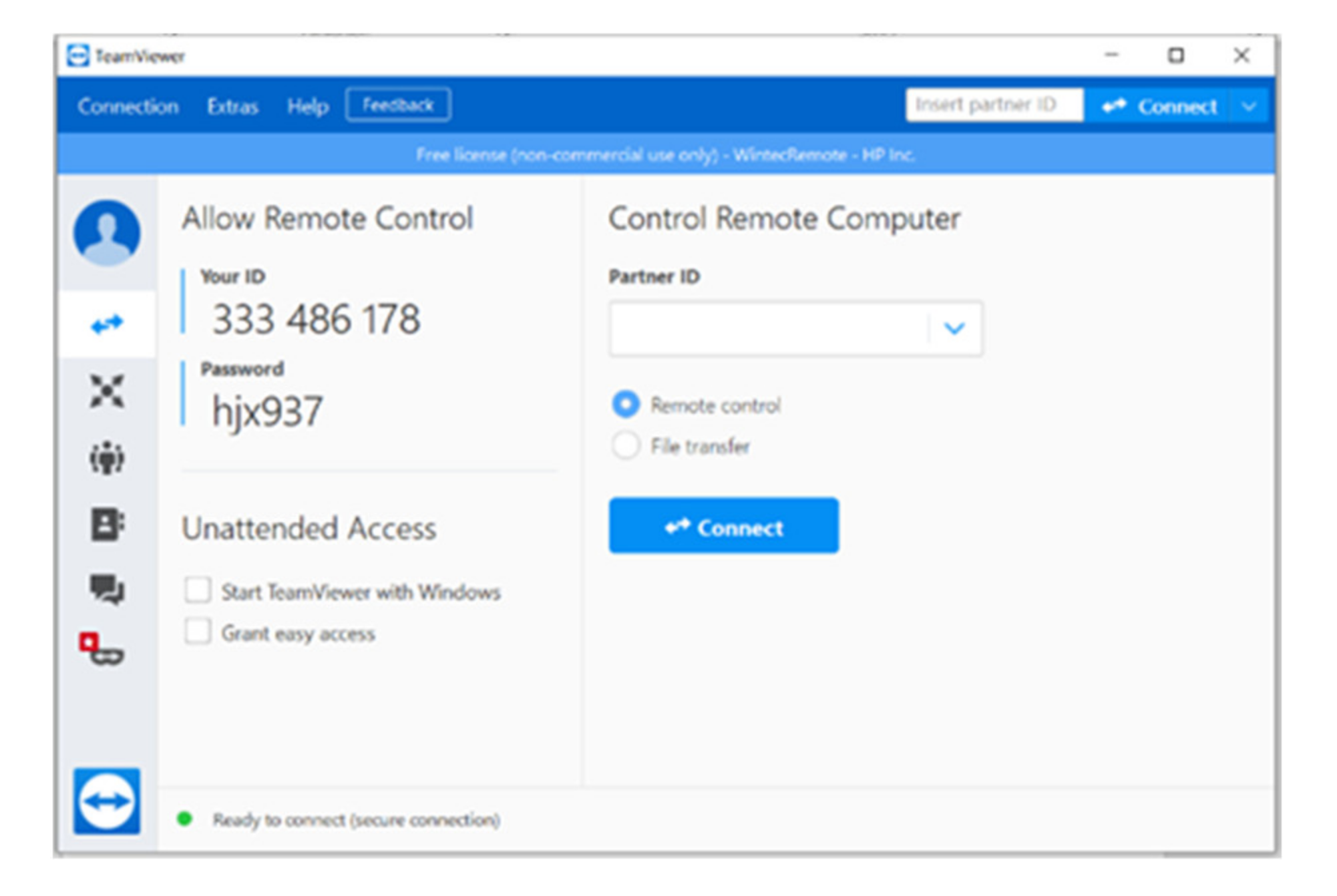
2.2.1. Remote Screen Sharing Software
The purpose of the screen-sharing software is to allow a remote student computer to access and control the laboratory computer which is connected to the experiment hardware. Three possible options to facilitate this were evaluated: TeamViewer [23], ISL Online [24], and Web Server [25].
TeamViewer is a remote access and control computer software that permits maintenance of computers and other devices. It requires software to be installed on both the remote computer and the laboratory computer. ISL Online also provides remote access and control of computers and mobile devices. It also requires software to be installed on both the remote computer and laboratory computer. A Web Server hosts a web application that provides features such as lab registration, scheduling, and logging. A lab server connection provides the addresses and application (interface) through which users can work on experiments. Software such as LabVIEW player simplifies the development of the application interface.
ISL Online and Web Server were not considered to be “low cost” for the development of the system. TeamViewer was selected for use because a functional free version is available that suits the requirements of the application. The main features of TeamViewer are:
- Remote wake, restart, and install of applications on devices running TeamViewer client;
- Secure remote access;
- Control of a remote computer or Android device as if a user were sitting in front of it.
Figure 7 illustrates the window that opens when TeamViewer is run on the remote computer. A partner ID and password (from the laboratory computer) is required to access and control the experiments on the laboratory computer.
Figure 7.
TeamViewer window.
2.2.2. Graphical User Interface (GUI) and Camera
The purpose of the GUI is to provide the control buttons and visual layout for facilitating the powering and selection of the hardware. This is achieved via communication with the micro-controller. It also monitors the status of the hardware and displays a live camera feed. This allows the remote user to operate the equipment in a safe manner.
The GUI is a Windows application and some programming languages that could be used to develop the application include C++, C#, Java, or Python. An important factor considered in the selection process was serial port communication to exchange data between the laboratory computer and micro-controller. Since there are many freely available tutorials on serial port communication with micro-controllers, the GUI was developed using Visual Studio [26] and C# programming language [27].
Since the control is effected by a micro-controller connected to the laboratory computer via USB, a standard USB web camera is sufficient to monitor the experiment hardware. A Logitech C920 HD Pro USB web camera [28] was selected for use (Figure 8). The camera has a diagonal field of view of 78°, dual microphones for stereo sound, auto focus, and auto light correction which are sufficient for the task.
Figure 8.
Logitech C920 HD Pro web camera.
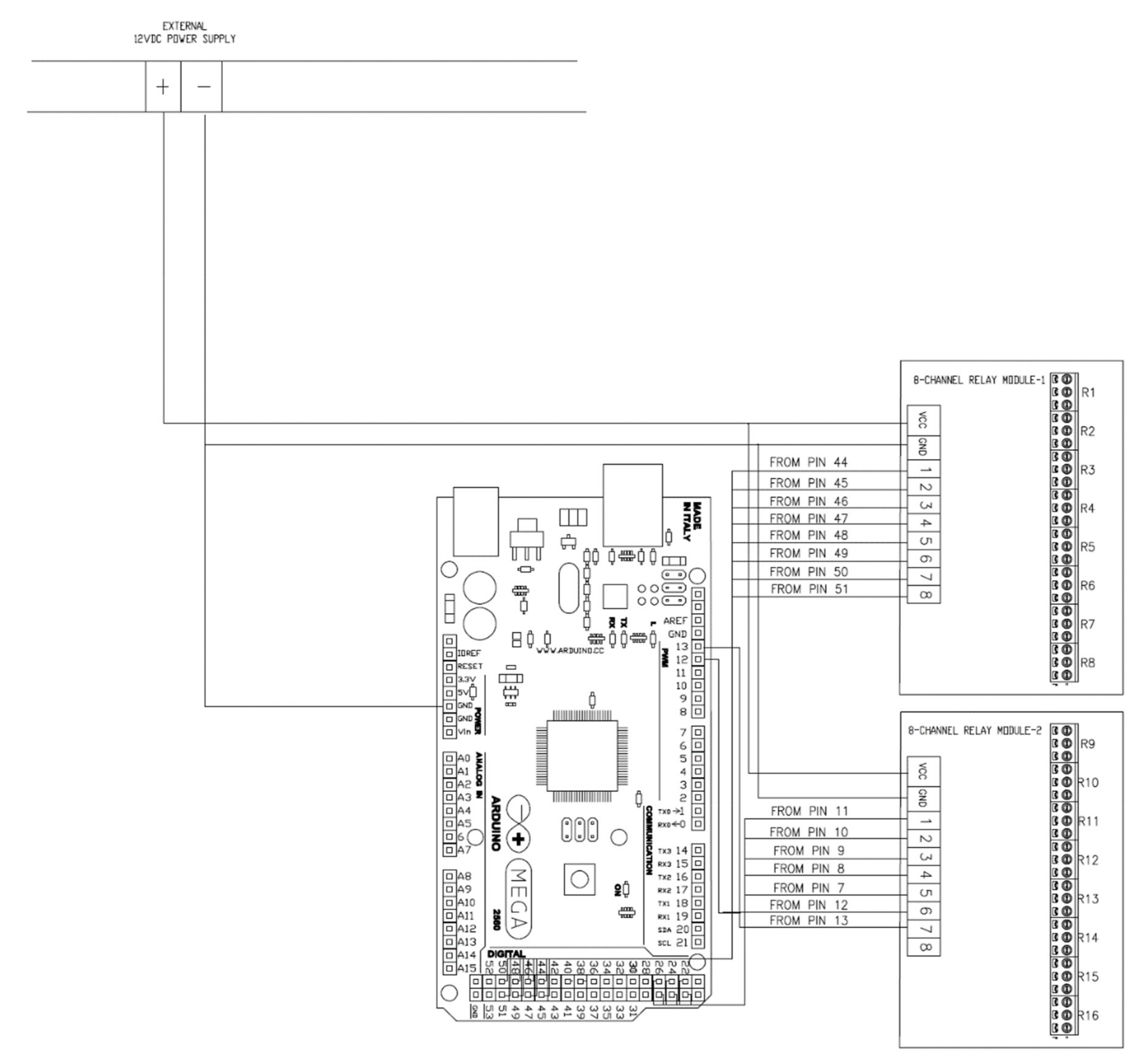
2.2.3. Micro-Controller
A micro-controller is required to interface the hardware apparatus to the GUI program on the laboratory computer for switching and control. The micro-controller decodes the serial port logic commands from the GUI and connects or disconnects the required hardware to the PLC. It also sends feedback to the GUI via serial communication.
A readily available example of controlling LEDs from a Visual Studio-based GUI via an Arduino micro-controller [29] was the inspiration for selecting the Duinotech MEGA 2560 r3 micro-controller [30]. The source code was developed in Visual Studio 2013 and required some modifications to be compatible with the latest versions of Visual Studio.
In this remote laboratory implementation, a USB cable connects the micro-controller to the laboratory computer. The USB cable is used for data communication and also provides sufficient power to run the micro-controller. The main reason for selecting the MEGA 2560 is that it has a large number of digital inputs and outputs to interface the two hardware experiments with the PLC. There are also sufficient additional pin connections to control more hardware experiments if required.
Arduino Integrated Development Environment (IDE) with C programming language was used to write and upload control programs to the Arduino board. Switching between the control lines of two hardware equipment is actuated by two sets of Arduino compatible 12 V 8-channel relay boards. Two additional sets of 12 V DPDT relay power on/off the machines. Figure 9 illustrates a simplified flowchart of the micro-controller control program. Various commands are sent from the GUI program to the micro-controller program to facilitate the switching of control and power lines. Figure 10 shows the micro-controller and 8-channel relay boards.
Figure 9.
Flowchart of the micro-controller control program.
Figure 10.
Micro-controller hardware. (a) Duinotech MEGA 2560 r3; (b) 8 channel relay boards [30].
3. Results
After selecting the components for the design, the GUI layout and programming, micro-controller programming, and hardware layout were prototyped. Sample PLC programs were also developed to test the operation of the hardware.
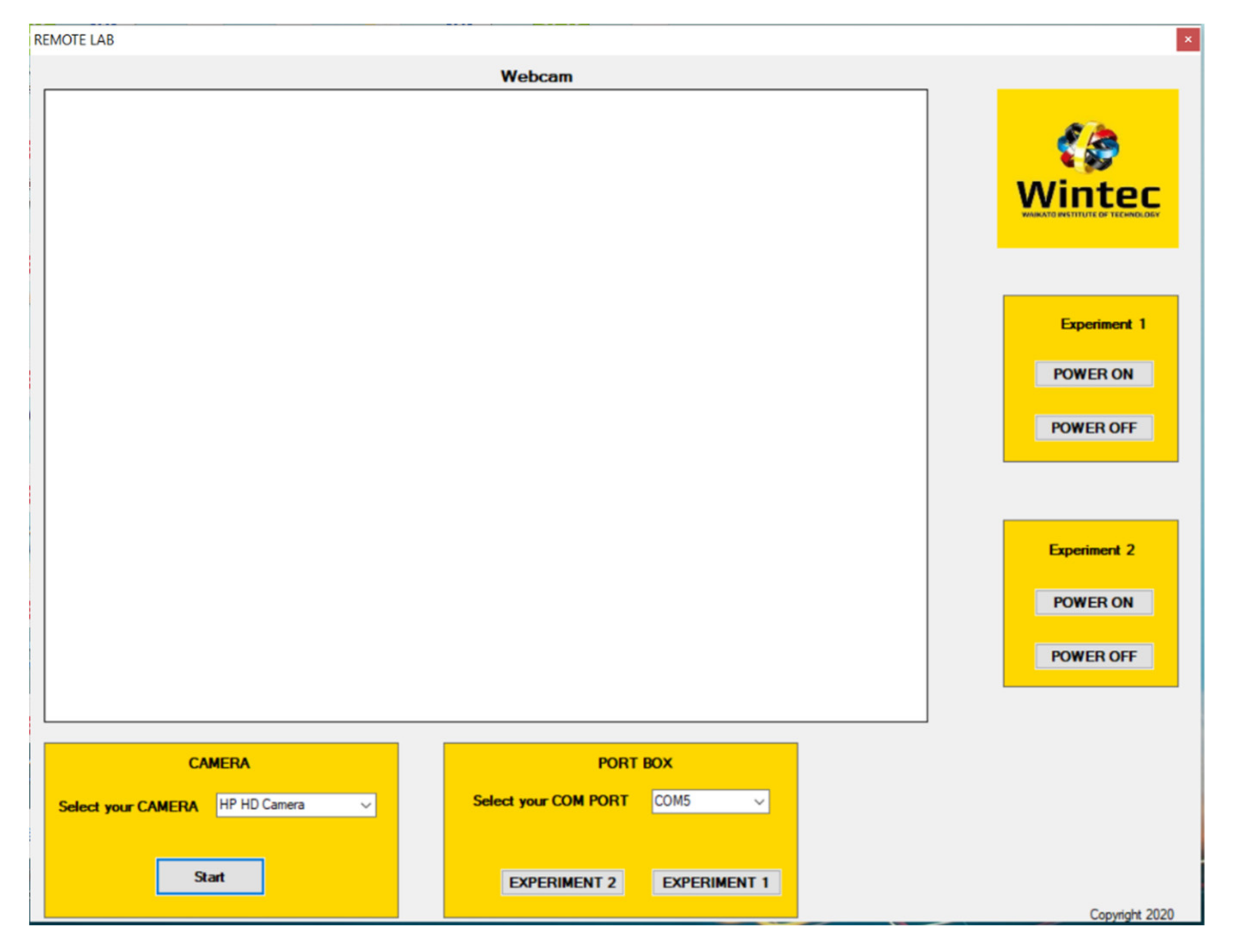
3.1. GUI Program Layout
Figure 11 illustrates the final layout of the GUI program. The key parts of the GUI are explained below:
Figure 11.
Layout of the GUI program.
- Video Screen—The white rectangular portion under the heading “Webcam” is allocated to show the video of the hardware. This is accomplished via the web camera installed in the lab. The video captured from the web camera inside the lab is made visible in this section with appropriate programming done with windows forms application.
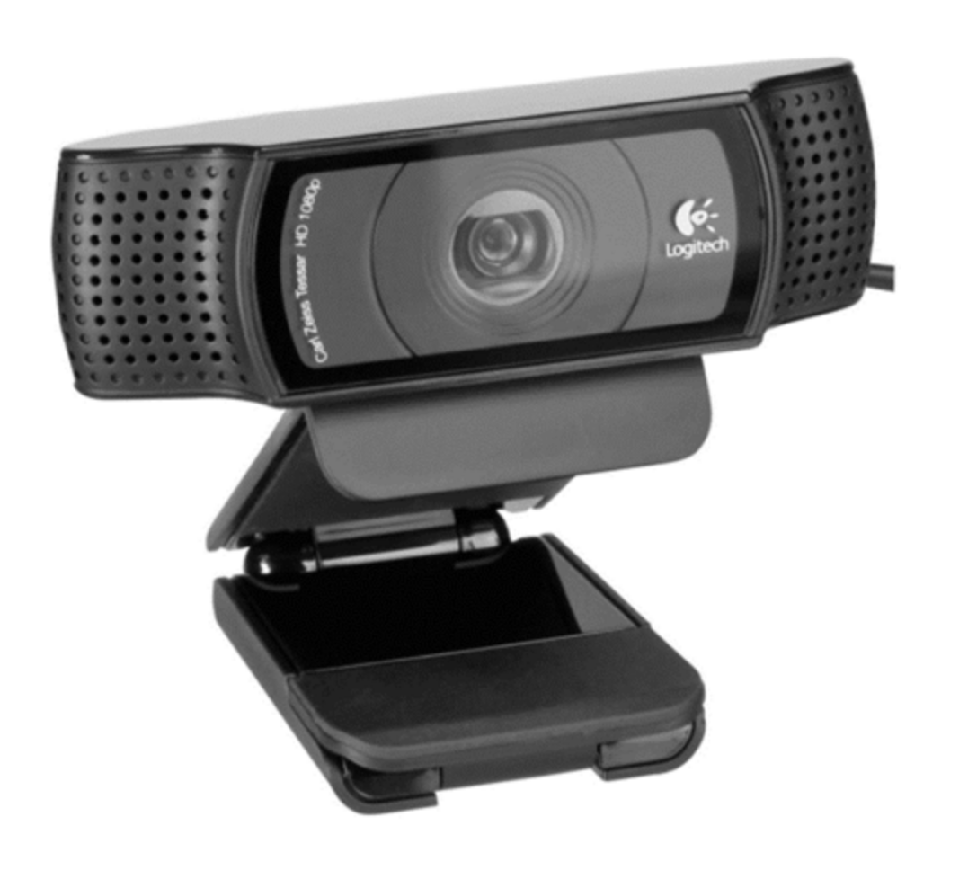
- Camera Selection—The yellow rectangular block in the bottom left corner of the window with the heading “CAMERA” is used to select the required camera from the list of cameras available. Since the laboratory computer is a laptop computer there is an option to select the built-in HD web camera or the Logitech C920 HD Pro.
- Experiment Selection—The yellow rectangular block in the bottom centre of the window with the heading “PORT BOX” is used for the selection of the experiment. Before selecting the experiment, the communication port must be selected from the drop-down menu. By default, this is COM3 to establish communication between the computer and the micro-controller.
- Experiment Power—The remaining two yellow blocks on the right side of the window are used to power on/off each hardware experiment individually.
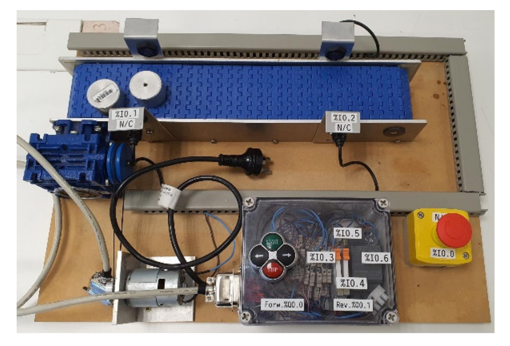
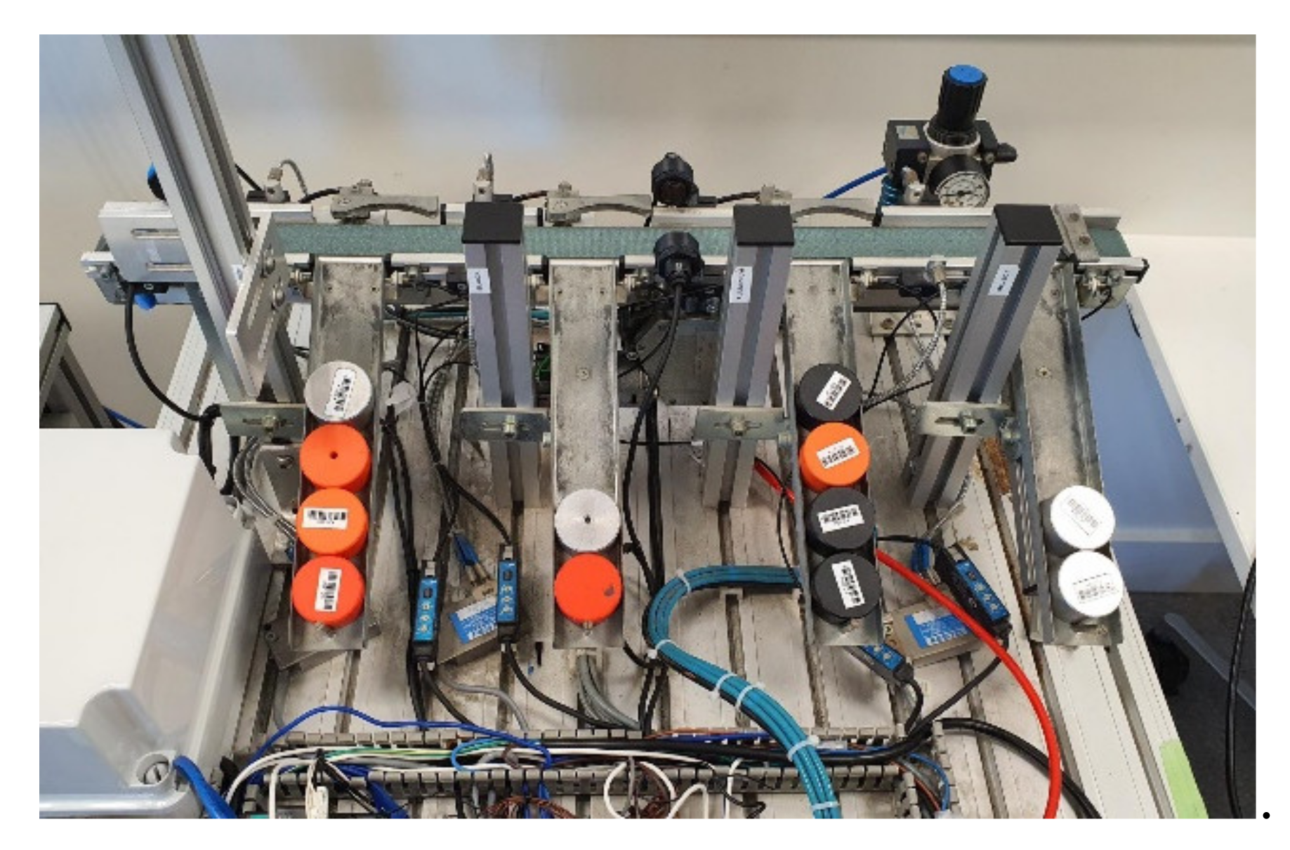
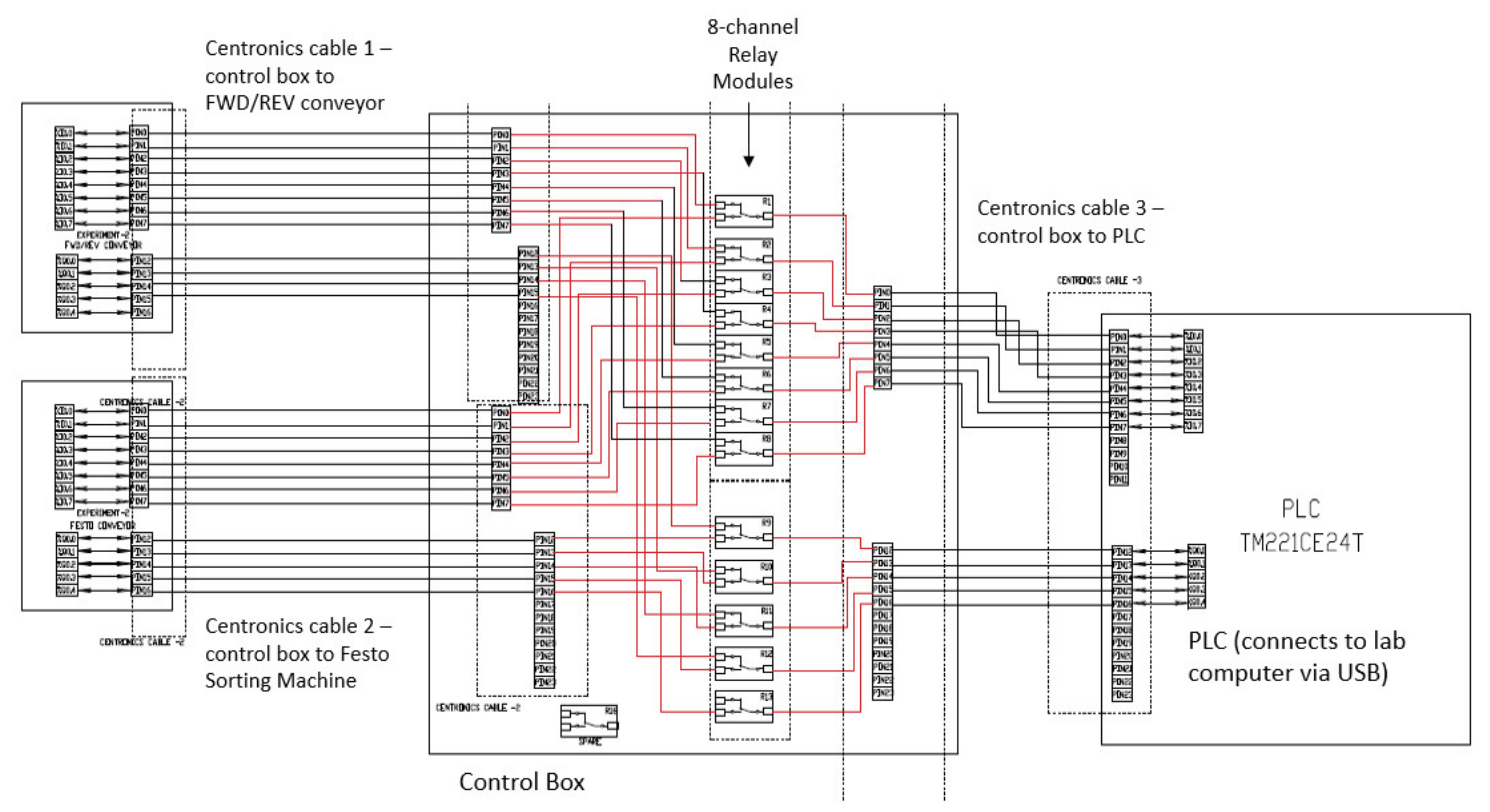
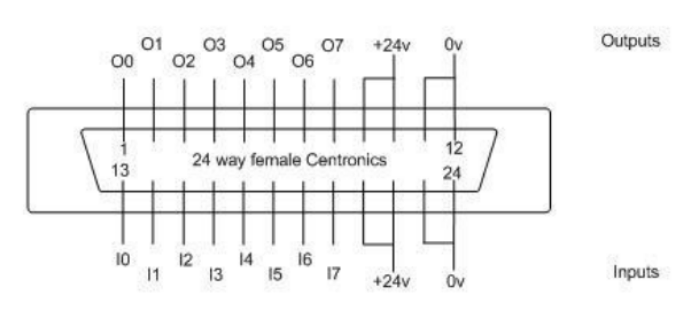
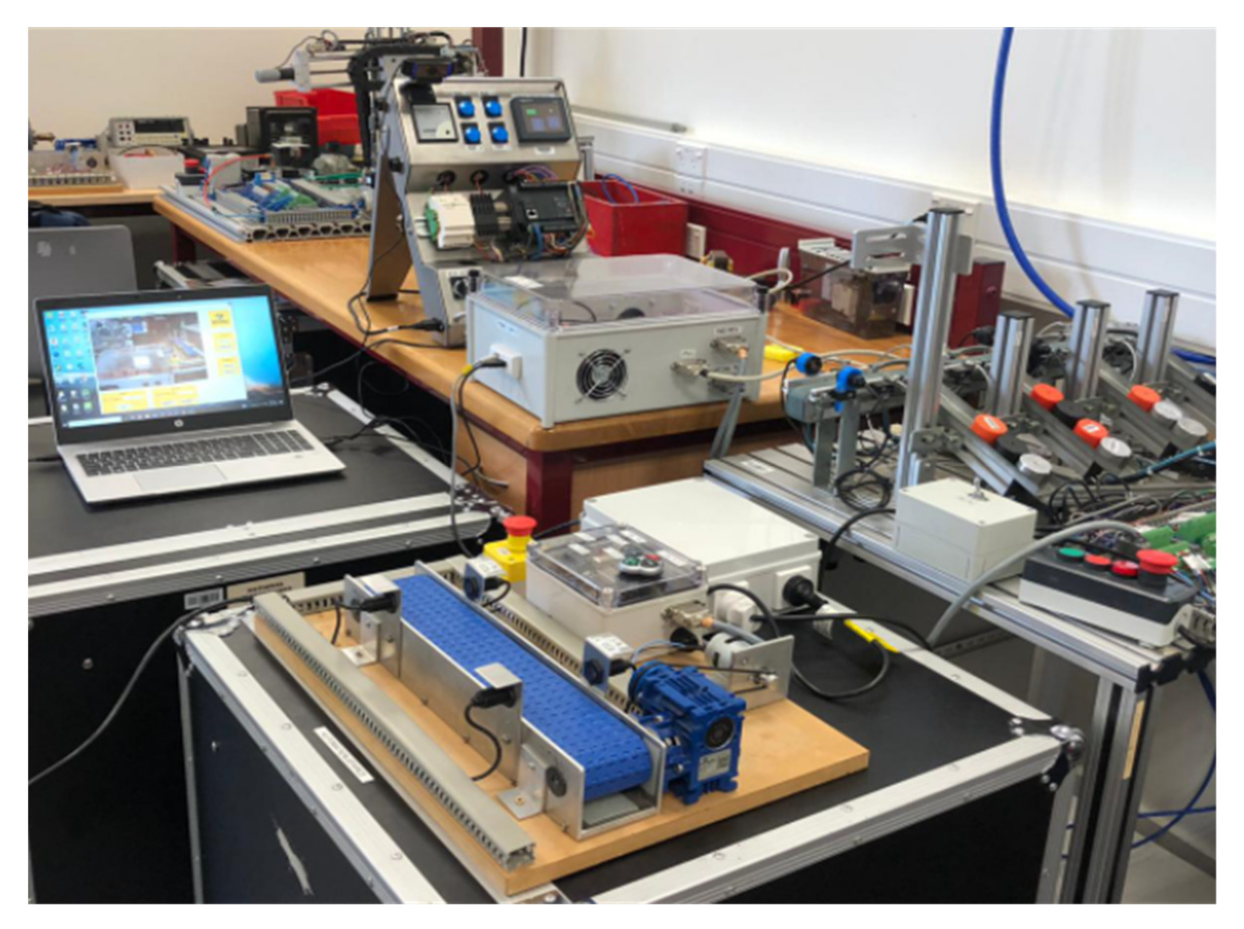
3.2. Micro-Controller and Hardware Wiring
The USB serial port connection between the laboratory computer and the micro-controller was set up with a baud rate of 9600. The micro-controller program preconfigures the pins and inputs or outputs and assigns a default value to the output pins. Figure 12 shows the sample code for serial communication of data on the Arduino micro-controller. A string of data is read from the GUI program, and the control lines are switched off when an “off” command is received.
Figure 12.
Arduino micro-controller sample serial communication code.
The wiring connections between the TM221CE24T PLC module and the two-experiment hardware is shown in Figure 13. The two 8-channel relay modules multiplex the connections to the PLC. When the relays are switched off, the lines are connected to the forward/reverse conveyor experiment. If the relays are energized via the GUI program, the control lines are switched over to the Festo sorting machine. Table 1 shows the input–output usage of the Centronics cable, and Figure 14 illustrates the physical pin connections. Figure 15 shows the connections between the power supply, Duinotech Mega 2560, and the 8-channel relay modules.
Figure 13.
Wiring connections between the TM221CE24T PLC module and the two hardware.
Table 1.
Input output usage of the Centronics cable.
Figure 14.
Physical pin connections of the Centronics cable.
Figure 15.
Power supply, Duinotech MEGA 2560, and relay modules connection.
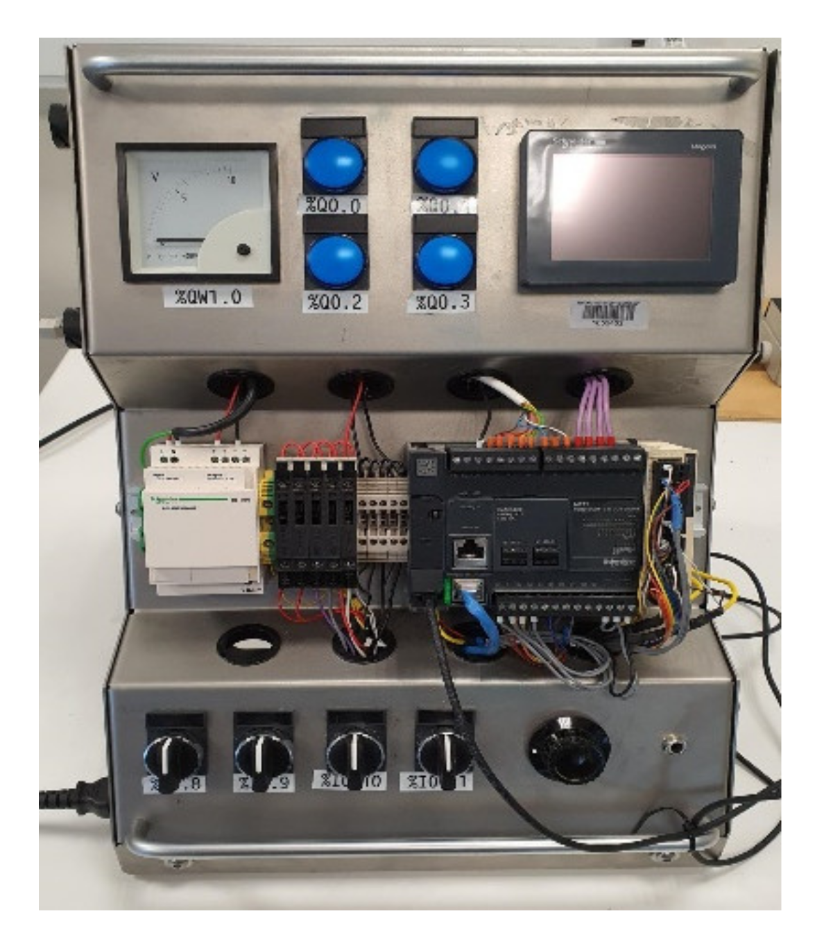
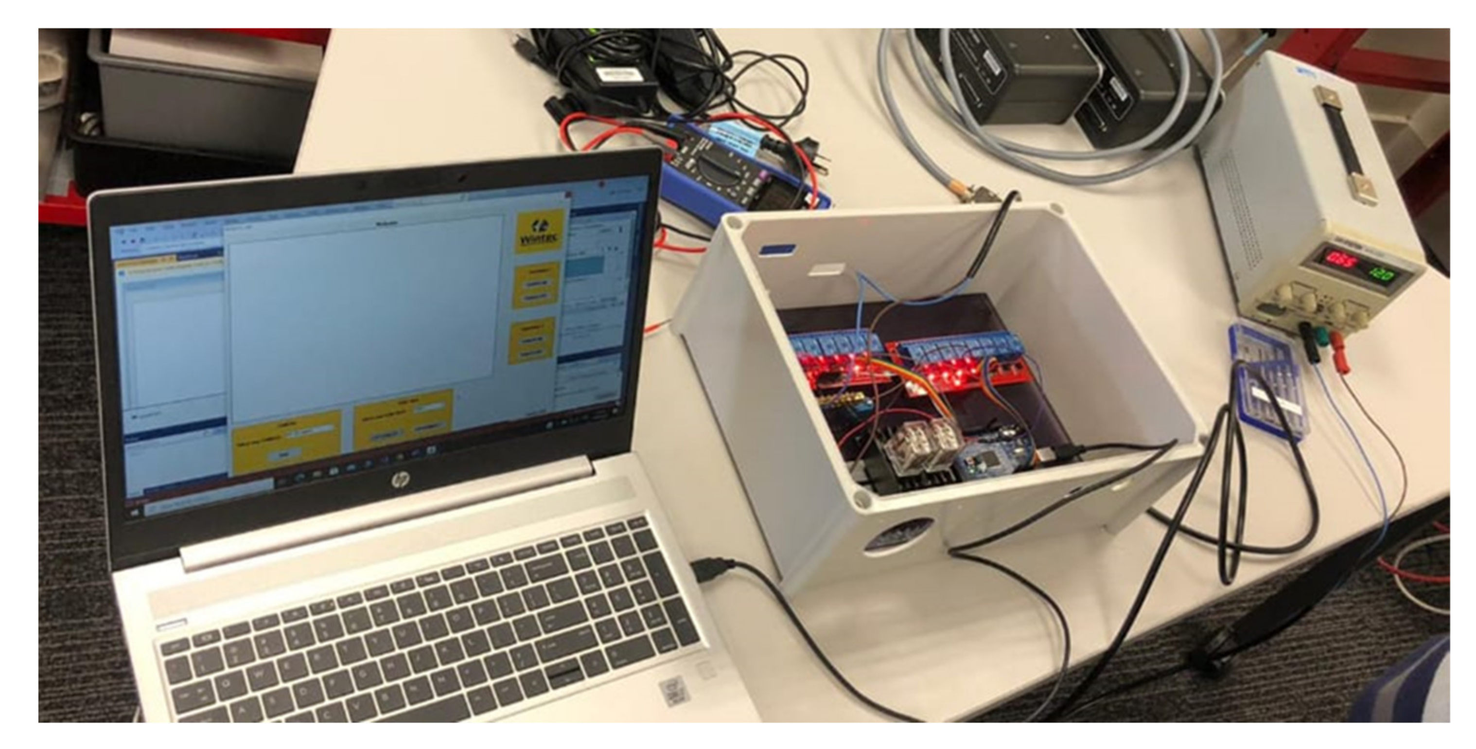
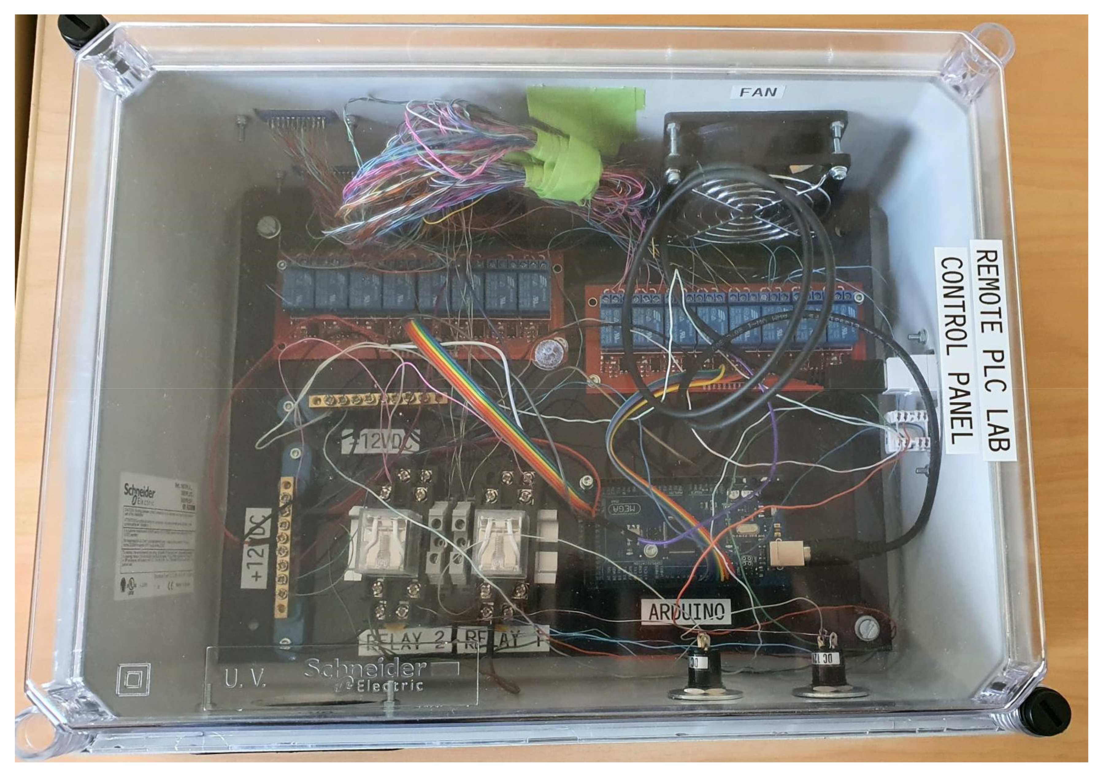
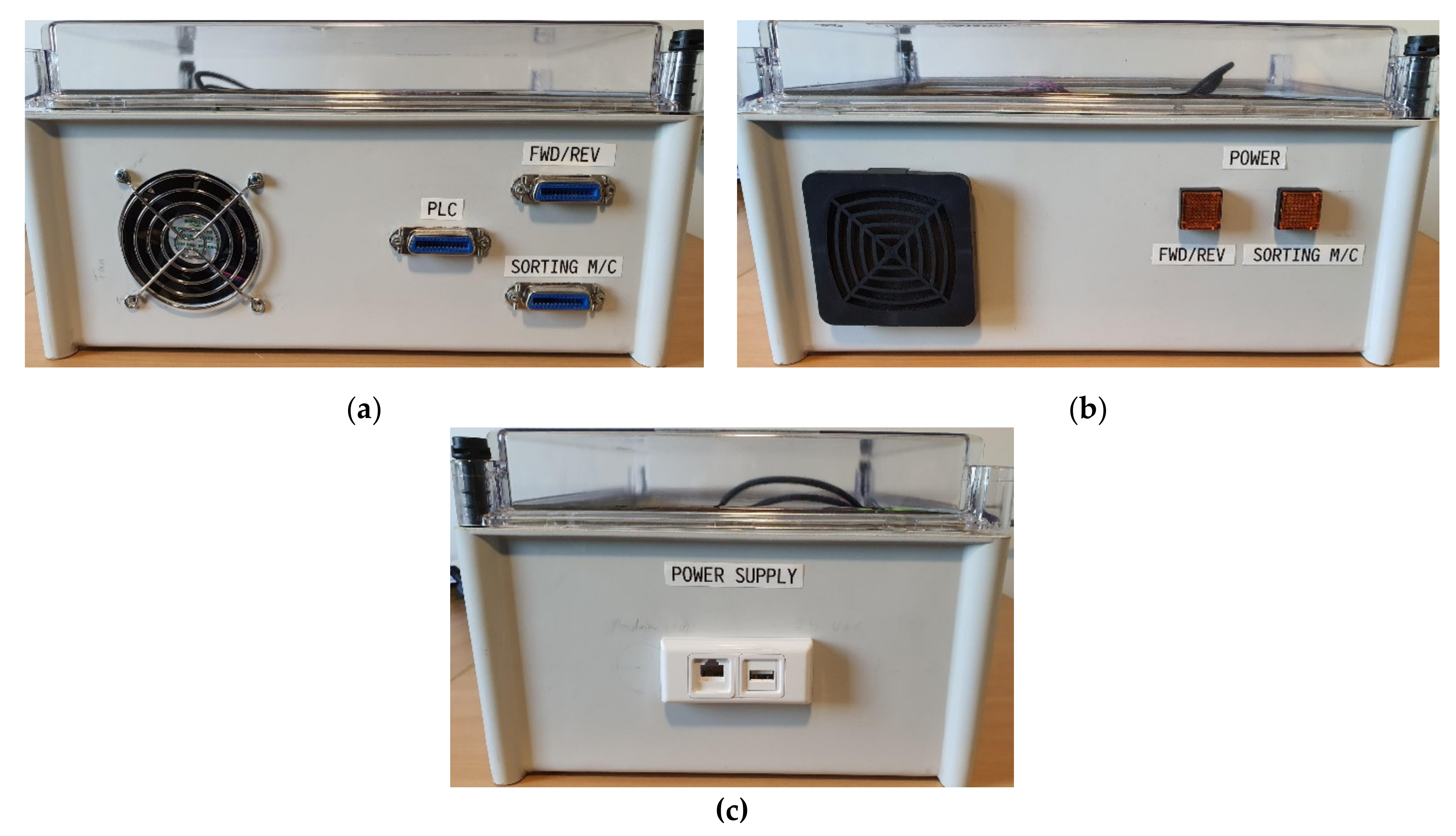
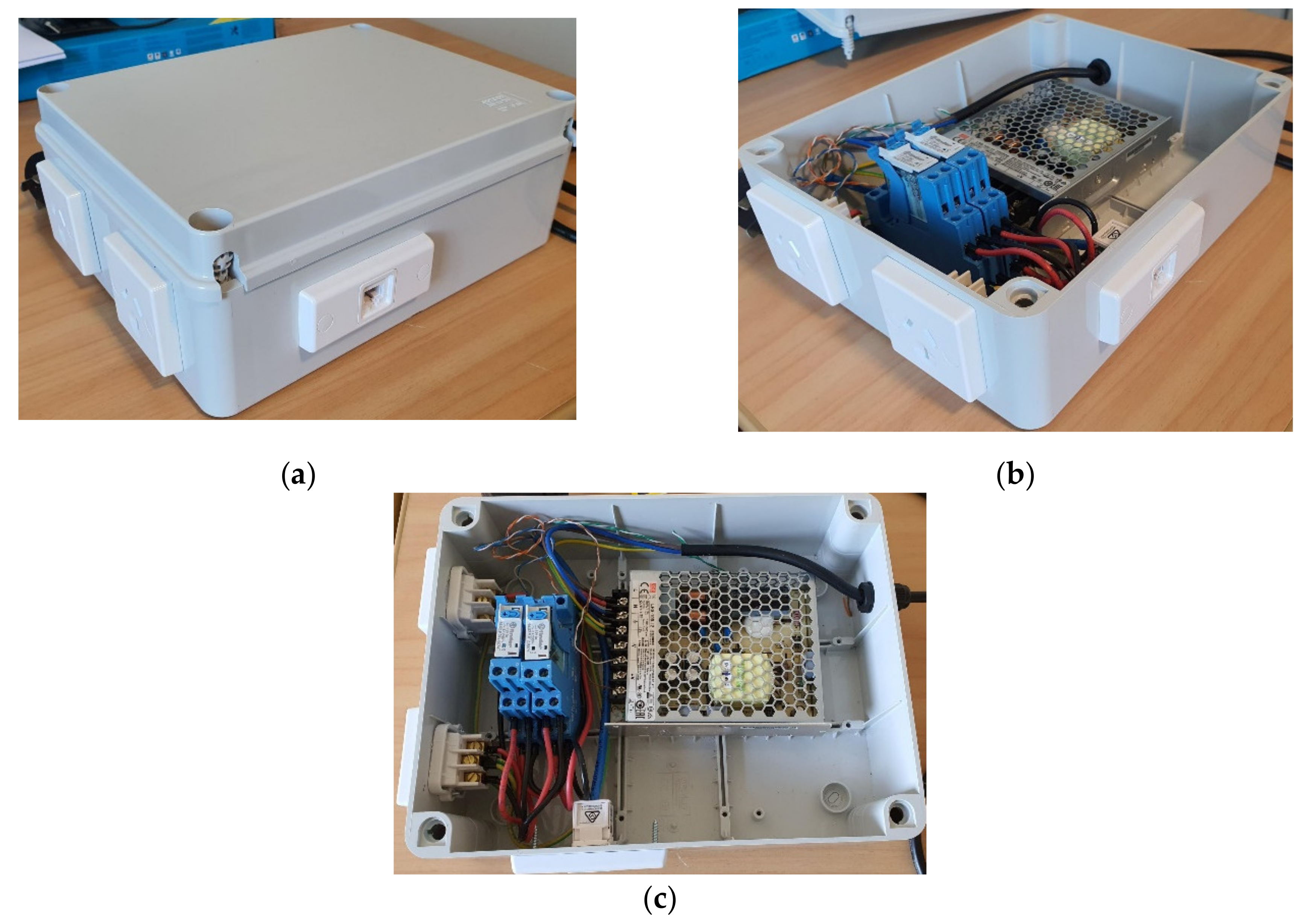
3.3. Control and Power Box Construction
After finalizing the wiring connections, the control and power boxes were constructed and the electronics assembled. The boxes were pre-sized ABS plastic cases. Perspex was used at the bottom of the boxes to mount the electrical and electronic components. Appropriate cut outs were made for external switches, lamps, connection ports, and ventilation fans. Following this, the power supply was tested with a multimeter. The physical connections within the control box were also tested for continuity and correct logic with a multimeter.
Figure 16 shows the control box after making the required holes and with the panel board fixed inside. The operation of the micro-controller with the relays were tested with an external power supply while the power supply box was being constructed. The commands to operate the relays via the micro-controller for switching the experiments were provided by the GUI program. The illuminated red lights indicate the successful testing procedure. Pictures of the fully assembled control box are shown in Figure 17 and Figure 18.
Figure 16.
Testing the GUI program controlling the 8-channel relays via the micro-controller.
Figure 17.
Fully assembled control box.
Figure 18.
Side views of the final control box. (a) Centronics cable connections and exhaust fan; (b) Indicator lamps for experiment selection and air inlet vent; (c) Power supply connections—USB for micro-controller, and ethernet for relay controls to power supply box.
The power supply box layout is shown in Figure 19. Relay control signals from the Control Box switch on/off the 230 V AC supplies to the experiment hardware. There are two AC sockets to connect the power supply for each hardware. The power supply box also provides the 24 V DC required for the PLC logic and experiment hardware.
Figure 19.
Power supply box layout. (a) Sealed box with 230 V AC and 24 V DC outputs; (b) Box with cover removed; (c) Plan view of open box showing relay connections and 24 V DC supply unit.
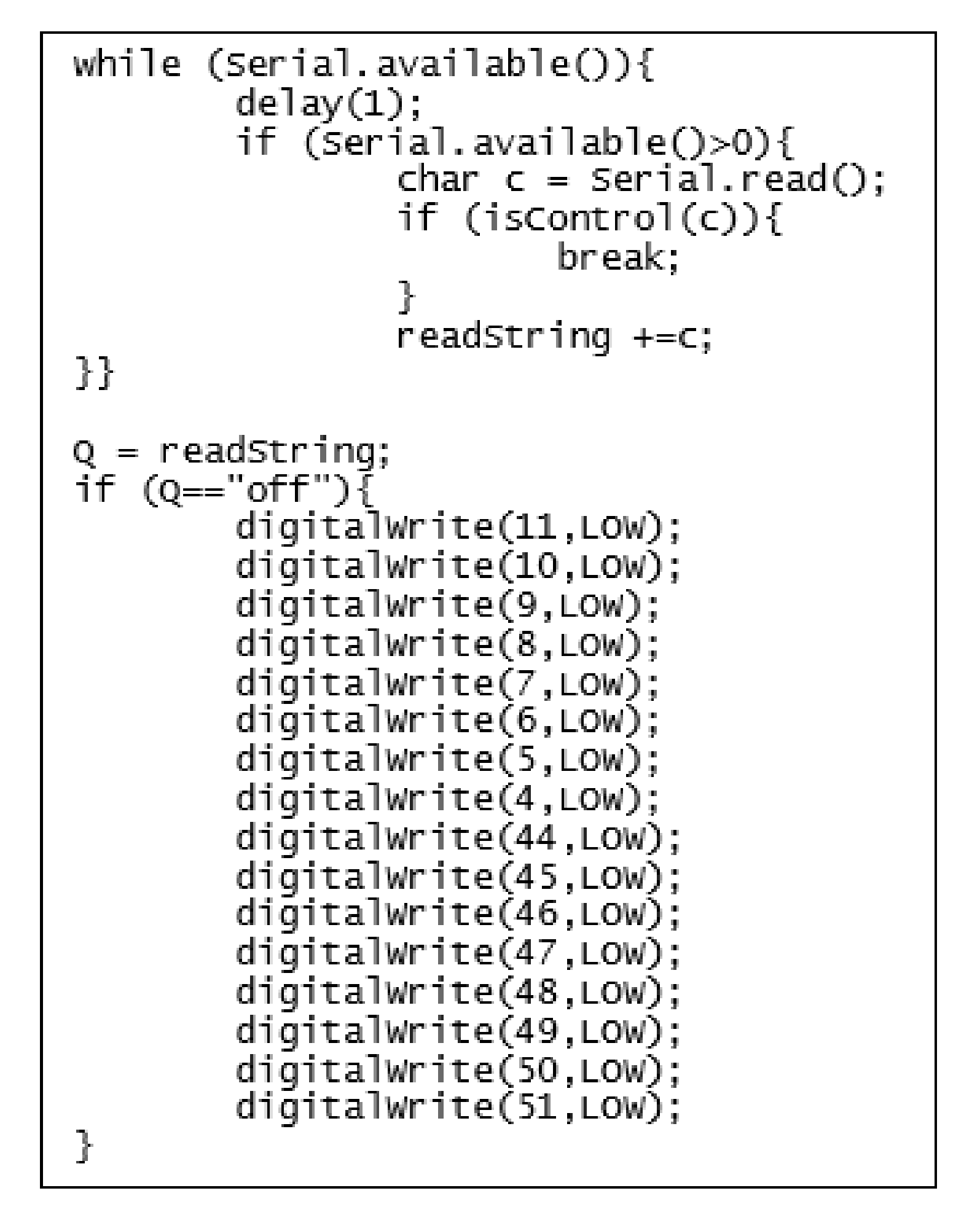
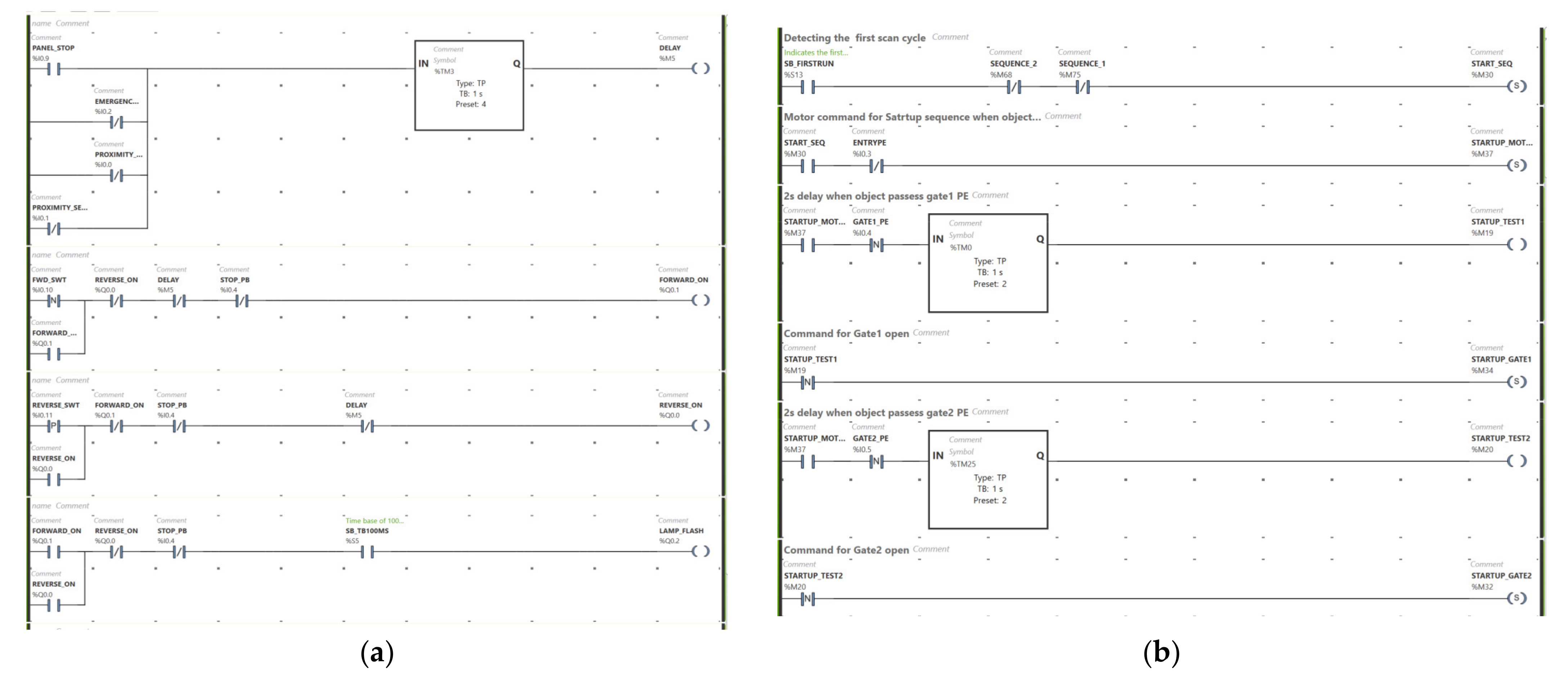
3.4. Sample PLC Programs
To test the operation of the experiment hardware, sample programs were written to read sensor inputs and send commands to actuators on each of the machines. SoMachine Basic PLC programming software was used for this. Figure 20 shows snippets of sample ladder logic programs to test the operation of the forward/reverse conveyor and the Festo sorting machine. The control line connections between the PLC and hardware were made via the GUI program.
Figure 20.
Sample ladder logic programs to test the operation of the experiment hardware. (a) Snippet of forward/reverse conveyor program; (b) Snippet of Festo sorting machine program.
Figure 21 shows the full remote laboratory system set up in a teaching space. The laboratory computer is set up to communicate on the Wintec Institute’s Wi-Fi network. The remote student computer (missing from Figure 21) was also present in the teaching space during testing. However, it was connected to Vodafone’s 4G mobile network. The remote computer was able to stream video and control the hardware without any lag or delay. A sample video of the full system in operation is available for viewing (Video S1: demo_video.mp4).
Figure 21.
Complete remote laboratory system set up.
4. Discussion
Each component of the remote laboratory system was tested individually as functional. The GUI and micro-controller programs successfully coordinate the selection and powering of hardware equipment. By using TeamViewer, the remote computer successfully connects to the PLC and downloads automation programs via USB. Users can use cloud storage such as Google Drive or Microsoft OneDrive to save their SoMachine programs.
The total cost of the prototype system based on the items listed in Table 2 is approximately NZD 650.00. This excludes the cost of the laboratory computer. A standard Windows 10 Intel Core i5 processor laptop computer is sufficient for the laboratory computer and would cost approximately NZD 1600.00. Hence, the overall cost (including laboratory computer) is approximately NZD 2250.00. This is relatively low-cost when compared with the implementations referenced in the introduction (Section 1). One of the main benefits of implementation presented in this paper is that all software used is free.
Table 2.
Parts list and cost of remote laboratory system.
The developed system can be used for other USB programmed PLC automation systems such as those based on Schneider Zelio Logic SR2/SR3 PLCs [31]. The programming software for the Zelio Logic PLCs is also free. This provides a useful tool to learn the basic concepts of PLC programming and to demonstrate simple automation on real physical equipment remotely.
User testing of the system was limited due to the current low enrolments of students in the PLC programming course. We have also been very fortunate to not have any COVID-19 lockdowns since the development of the system. However, the system was developed by former students of the PLC programming course, and they took feedback from former students in the form of verbal interviews. International students, who typically require additional time for completing practical work due to part-time work commitments, have rated the system as being easy to access and control remotely. In addition to this, it was straightforward for them to transition working on their practical work both on-campus and off-campus.
5. Conclusions
This paper presented the design and construction of a low-cost system for remotely accessing and controlling multiple automation equipment. The system provides the remote user/programmer with an experience of using the equipment that is similar to use when physically present with the equipment. A GUI program allows the remote user to power and select machines for operation. The prototype system was constructed, tested, and correct remote operation was verified.
Currently, the remote lab system controls two hardware equipment. Control of additional hardware can be achieved by interfacing additional relays to unused pins of the micro-controller. Future work will include extending the system to other machinery/equipment that could benefit from having remote access and control. Remote pan-tilt capabilities can be added to the camera control to improve remote viewing.
Supplementary Materials
The following are available online at https://www.mdpi.com/article/10.3390/machines9070138/s1, Video S1: demo_video.mp4.
Author Contributions
The authors contributions are as follows: Conceptualization, P.C.; methodology, P.C., S.J., J.A. and J.J.; software, S.J., J.A. and J.J.; validation, S.J., J.A. and J.J.; formal analysis, P.C.; investigation, P.C., S.J., J.A. and J.J.; resources, P.C. and M.A.-R.; writing—original draft preparation, P.C., S.J., J.A. and J.J.; writing—review and editing, P.C. and M.A.-R.; supervision, P.C. and M.A.-R.; project administration, P.C. and M.A.-R.; funding acquisition, P.C. All authors have read and agreed to the published version of the manuscript.
Funding
This research received no external funding.
Institutional Review Board Statement
Not applicable.
Informed Consent Statement
Not applicable.
Data Availability Statement
Not applicable.
Acknowledgments
The authors would like to thank the Wintec Research Office and Centre for Engineering and Industrial Design for internal funding to support this research. Timothy Fargher, Engineering Technician, also provided technical support and advice during the construction stage. Frank Beinersdorf was also involved in initial discussions about testing the remote system from another educational institute in New Zealand.
Conflicts of Interest
The authors declare no conflict of interest.
References
- Chand, P.; Al-Rawi, M.; Khanna, J. Utilising Digital Assessment Strategies for Theory & Practical Work in Mechatronics. In Proceedings of the AAEE2020 Conference, Sydney, NSW, Australia, 6–9 December 2020. [Google Scholar]
- Hoult, R.D.; Miramini, S.; Lumantarna, E. Promoting effectiveness of student learning in a flipped or blended approach. In Proceedings of the AAEE2020 Conference, Sydney, NSW, Australia, 6–9 December 2020. [Google Scholar]
- Buskes, G. Disrupting a flipped classroom to become fully online. In Proceedings of the AAEE2020 Conference, Sydney, NSW, Australia, 6–9 December 2020. [Google Scholar]
- Alkhaldi, T.; Pranata, I.; Athauda, R.I. A review of contemporary virtual and remote laboratory implementations: Observations and findings. J. Comput. Educ. 2016, 3, 329–351. [Google Scholar] [CrossRef]
- Chaos, D.; Chacón, J.; Lopez-Orozco, J.A.; Dormido, S. Virtual and Remote Robotic Laboratory Using EJS, MATLAB and LabVIEW. Sensors 2013, 13, 2595–2612. [Google Scholar] [CrossRef] [PubMed]
- Marques, M.; Viegas, M.; Costa-Lobo, M.; Fidalgo, A.; Alves, G.; Rocha, J.; Gustavsson, I. How Remote Labs Impact on Course Outcomes: Various Practices Using VISIR. IEEE Trans. Educ. 2014, 57, 151–159. [Google Scholar] [CrossRef]
- Prieto-Blazquez, J.; Herrera-Joancomarti, J.; Guerrero-Roldán, A. A virtual laboratory structure for developing programming labs. Int. J. Emerg. Technol. Learn. 2009, 4, 47–52. [Google Scholar] [CrossRef] [Green Version]
- Maiti, A.; Zutin, D.G.; Wuttke, H.; Henke, K.; Maxwell, A.D.; Kist, A.A. A Framework for Analyzing and Evaluating Architectures and Control Strategies in Distributed Remote Laboratories. IEEE Trans. Learn. Technol. 2018, 11, 441–455. [Google Scholar] [CrossRef]
- Pasc, M.I.; Tarca, R.-C.; Vesselenyi, T.; Popentiu-Vladicescu, F.; Nagy, R.-B. Remote Educational System Using Virtual and Augmented Reality. In Proceedings of the 11th International Scientific Conference eLearning and Software for Education, Bucharest, Romania, 23–24 April 2015; pp. 221–228. [Google Scholar]
- García-Guzmán, F.; Villa-López, H.; Vélez-Enríquez, J.A.; García-Mathey, L.A.; Ramírez-Ramírez, A. Remote Laboratories for Teaching and Training in Engineering. In Design, Control and Applications of Mechatronic Systems in Engineering; Yildirim, S., Ed.; InTech Open: London, UK, 2017; pp. 47–63. [Google Scholar]
- De Lima, P.C.; Carlos, L.M.; Simão, J.P.S.; Pereira, J.; Mafra, P.M.; da Silva, J.B. Design and implementation of a remote lab for teaching programming and robotics. IFAC Pap. 2016, 49, 86–91. [Google Scholar] [CrossRef]
- Michalec, T.; Wojczuk, M.; Brzoza-Woch, R.; Szydło, T. Remote Programming and Reconfiguration System for Embedded Devices. In Proceedings of the 2019 Federated Conference on Computer Science and Information Systems (FedCSIS), Leipzig, Germany, 1–4 September 2019; pp. 467–470. [Google Scholar]
- Anzhelika, P.; Olga, G.; Ivanov, E.; Sokolyanskii, A.; Kurson, S. Development and application of remote laboratory for embedded systems design. In Proceedings of the 2015 12th International Conference on Remote Engineering and Virtual Instrumentation (REV), Bangkok, Thailand, 25–27 February 2015; pp. 69–73. [Google Scholar]
- OBellmunt, G.; Miracle, D.M.; Arellano, S.G.; Sumper, A.; Andreu, A.S. A distance PLC programming course employing a remote laboratory based on a flexible manufacturing cell. IEEE Trans. Educ. 2006, 49, 278–284. [Google Scholar] [CrossRef]
- Goman, V.; Fedoreev, S. Remote training of programming of PLC with embedded web server. EAI Endorsed Trans. Energy Web Inf. Technol. 2018, 5, 1–5. [Google Scholar] [CrossRef] [Green Version]
- Palma, L.B.; Brito, V.; Rosas, J.; Gil, P. WEB PLC simulator for ST programming. In Proceedings of the 2017 4th Experiment@International Conference (exp.at’17), Faro, Portugal, 6–8 June 2017; pp. 303–308. [Google Scholar] [CrossRef]
- Shyr, W.-J.; Su, T.-J.; Lin, C.-M. Development of Remote Monitoring and a Control System Based on PLC and WebAccess for Learning Mechatronics. Int. J. Adv. Robot. Syst. 2013, 10, 97. [Google Scholar] [CrossRef] [Green Version]
- Sheng-Jen, H. Design of Remotely Accessible Automated Systems to Enhance Industrial Automation Education, Columbus, Ohio. 2017. Available online: https://peer.asee.org/27878 (accessed on 15 July 2021).
- Colak, I.; Efe, A. Design and implementation of a remote access PLC training set. In Proceedings of the International Aegean Conference on Electrical Machines and Power Electronics and Electromotion, Joint Conference, Istanbul, Turkey, 8–10 September 2011; pp. 425–429. [Google Scholar] [CrossRef]
- Mendes, M.J.G.C.; Martins, L. An internet remote laboratory to teach Industrial Automation. In Proceedings of the 2014 7th International Conference on Human System Interactions (HSI), Costa da Caparica, Portugal, 16–18 June 2014; pp. 144–149. [Google Scholar] [CrossRef]
- Chand, P.; James, S.; Antony, J.; Jose, J. Developing Remote Access and Control of Automation Equipment. In Proceedings of the 7th International Conference on Control, Automation and Robotics, Singapore, 23–25 April 2021; pp. 31–35. [Google Scholar]
- Schneider-Electric. Modicon M221 Logic Controller User Guide; Schneider Electric: Neuss, Germany, 2020. [Google Scholar]
- Drugarin, C.V.A.; Draghici, S.; Raduca, E. Team Viewer Technology for Remote Control of a Computer. Analele Universităţii Eftimie Murgu Reşiţa 2016, 23, 61–66. [Google Scholar]
- ISL-Online. REMOTE Support. Access. Work. Available online: https://www.islonline.com/nz/en/ (accessed on 5 March 2021).
- Farag, W. An Innovative Remote-Lab Framework for Educational Experimentation. Int. J. Online Biomed. Eng. 2017, 13, 68–86. [Google Scholar] [CrossRef] [Green Version]
- Strauss, D. Getting Started with Visual Studio 2019; Apress Media: Berkeley, CA, USA, 2020. [Google Scholar]
- Conrod, P.; Tylee, L. Learn Visual C#, 2019 ed.; Kidware Software: Maple Valley, WA, USA, 2019. [Google Scholar]
- Logitech. C920 HD PRO WEBCAM. Available online: https://www.logitech.com/en-nz/product/hd-pro-webcam-c920#specification-tabular (accessed on 5 March 2021).
- Currey, M. Arduino and Visual Basic Part 1: Receiving Data From the Arduino. Available online: http://www.martyncurrey.com/arduino-and-visual-basic-part-1-receiving-data-from-the-arduino/ (accessed on 5 March 2021).
- Jaycar-NZ. Duinotech MEGA 2560 r3 Board for Arduino. Available online: https://www.jaycar.co.nz/duinotech-mega-2560-r3-board-for-arduino/p/XC4420?gclid=Cj0KCQiAyoeCBhCTARIsAOfpKxig7maxgyOBNBOhqSabgkDAYnI5Z00YCs-JJonW1GSez_oHKOd7_mgaAiHOEALw_wcB (accessed on 5 March 2021).
- Schneider-Electric. Zelio Logic Smart Relay User Manual; Schneider Electric: Neuss, Germany, 2017. [Google Scholar]
Publisher’s Note: MDPI stays neutral with regard to jurisdictional claims in published maps and institutional affiliations. |
© 2021 by the authors. Licensee MDPI, Basel, Switzerland. This article is an open access article distributed under the terms and conditions of the Creative Commons Attribution (CC BY) license (https://creativecommons.org/licenses/by/4.0/).