Abstract
The low speed toothed doubly salient permanent-magnet (TDSPM) machine is an interesting candidate motor for electric ship applications because, of its high torque output, maintenance-free operation and flexible working modes, which gives the opportunity to increase system’s reliability, and decrease the system size, weight and noise which are key features for naval applications. However, particularly in the 3-phase configuration, the stator and rotor saliency of these machines leads to a high level of torque ripple. To overcome these drawbacks, the use of polyphase machines (with a number of phases greater than three) can be a relevant solution. In this paper, an optimal design of two kind of novel 4-phase motors is performed in order to fulfil the specifications of a high power naval ship propulsion. The designs aim to maximize the torque to mass ratio. The motors’ performances are directly linked to their structural parameters, so, the impact of the coil number in terms of mean torque, torque ripple, energy ratio values, and efficiency is also presented and analysed. The design of these two electromagnetic structures, as well as the determination of their electromagnetic performances, are carried out using a particle swarm optimization algorithm (PSO) with taking into account thermal constraint. The performance of the proposed machine in terms of mean torque, torque ripple, energy ratio, and efficiency values is presented and analysed. The results obtained reveal that the TDSPM machines with four poles/phase are good candidates to meet the requirements of high power direct-drive ship propulsion system.
1. Introduction
In ships (research vessels and special purpose ships), increasing compactness is challenging. A benefit of electric propulsion is that it gives supplementary degrees of freedom from a naval architecture point of view. It allows better use of the main ship volumes, a breakthrough in efficiency, maneuverability, reliability and flexibility of operations [].
The electric machines used for the propulsion have to offer high efficiency, high power density and maintenance-free operation. To achieve these goals, numerous research studies have been conducted on various electrical motors topologies associated with power electronics drives as well as conventional wound field synchronous machines (WFSMs), permanent magnet synchronous machines (PMSMs), induction machines (IMs) and unconventional permanent magnet structures [,,,,,,,,,,,,].
In general, PMSMs present high power density in high-speed operation. However, in low-speed applications, the achievement of increased power density and low torque ripple is challenging, usually demanding a complex design for performing a better electrical performance []. This is why unconventional permanent magnet structures have received much attention recently.
The specificity of the stator-PM doubly salient toothed poles machines which are proposed and studied in this paper is that, the PMs are located in the stator yoke. This point differs significatively from other machine topologies which can be proposed for marine propulsion motor application such as stator PM Flux switching motors or classical PM motors where PMs are located in the stator teeth or housed in the rotor respectively [,,]. This feature allows a priori to increase the simplicity and the robustness of the machine design and to use only a very limited number of magnets. It also includes large-toothed poles which carry a large number of small rotor teeth leading to the decrease, for a given electrical frequency, of the rotor speed. The latter is because the rotor speed varies inversely with the number of rotor teeth. Furthermore, the phase windings and the excitation system are fully located in the stator, while the rotor does not contain magnets and coils. These points are key features for low speed and high torque applications such as marine propulsion motors.
Compared to classical structures, the aforementioned structure appears as an interesting option for naval application; it has the advantage of simplicity in construction, presents robustness and is able to produce high torque [,].
However, the stator and rotor saliency of these machines leads to a high level of torque ripple (especially in three-phase TDSPM) resulting in acoustic noise and vibration [,]. To overcome these drawbacks, the use of polyphase machines (number of phases greater than three) can be a relevant solution.
On the other hand, obtaining increased power density and low torque ripple in low speed operation is also challenging. The performance of these stator-PM doubly salient toothed pole machines is linked to their structural parameters (number of rotoric teeth, number of statoric pole teeth), the teeth geometry of the stator and rotor, the number of poles and the number of pairs of magnets. In addition, when the number of magnets is smaller than the number of wound poles in the stator, the value of total flux will decrease due to the armature reaction, as well as, their amplitudes becomes asymmetric due to the location of the permanent magnets. These phenomena affect the torque quality (torque ripples) and the torque density.
In previous works, by the same team, three multiphase machines which have the same external volume, are studied []. The study is limited only to 3-phase, 4-phase and 5-phase configurations with four coils/phase. This study revealed that the 4-phase TDSPM presents the better objective function value (maximal torque to mass ratio) and a highest torque value compared to 3- and 5-phase structures.
In this paper, based on the results of the work carried out in [], and in order to study the coils number impact on the the mean torque, torque ripple, energy ratio which characterizes the sizing of the motor power supply [,], and effeciency of these types of machines, the TDSPM machine with four phases is chosen.
The studied 4-phase machine configurations are given in Figure 1a,b. The first configuration is with two coils per phase and the second is with four coils per phase, respectively. A concentrated winding has been chosen to increase machine compactness and efficiency. The design of these structures use an optimization method in order to maximize the torque to mass ratio with the same external volume and output power.
Figure 1.
Proposed 4-phase TDSPM machine, (a) with two coils/phase, (b) with four coils/phase.
The optimization method employed and applied to the TDSPM machines design is the particle swarm optimization (PSO) combined to the FEMM sofware used to perform Finite Element Analysis. The proposed machines under study are governed by a set of specifications presented in Table 1, which corresponds to a PM synchronous machine dedicated to high power propulsion []. This reference machine is proposed from an industrial realistic design point of view. Both two and four coils per phase structures are studied and compared.
Table 1.
TDSPM design specifications and constraints [].
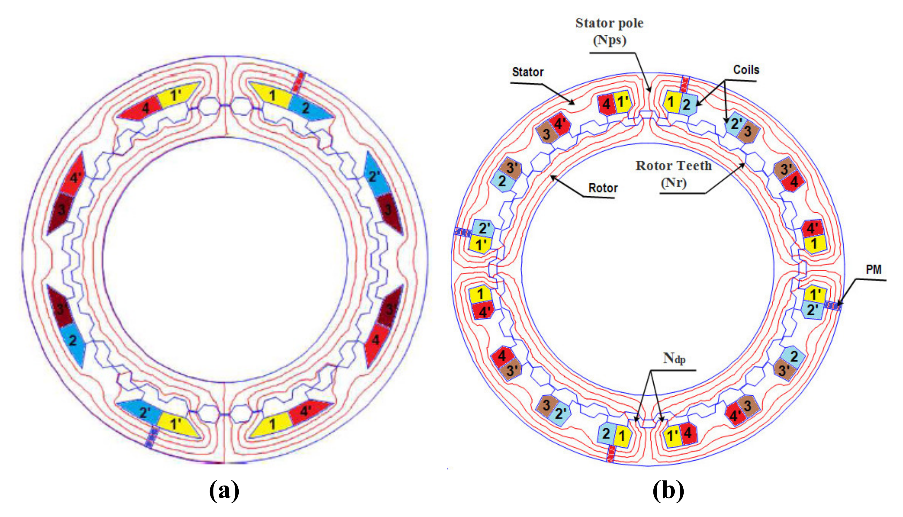
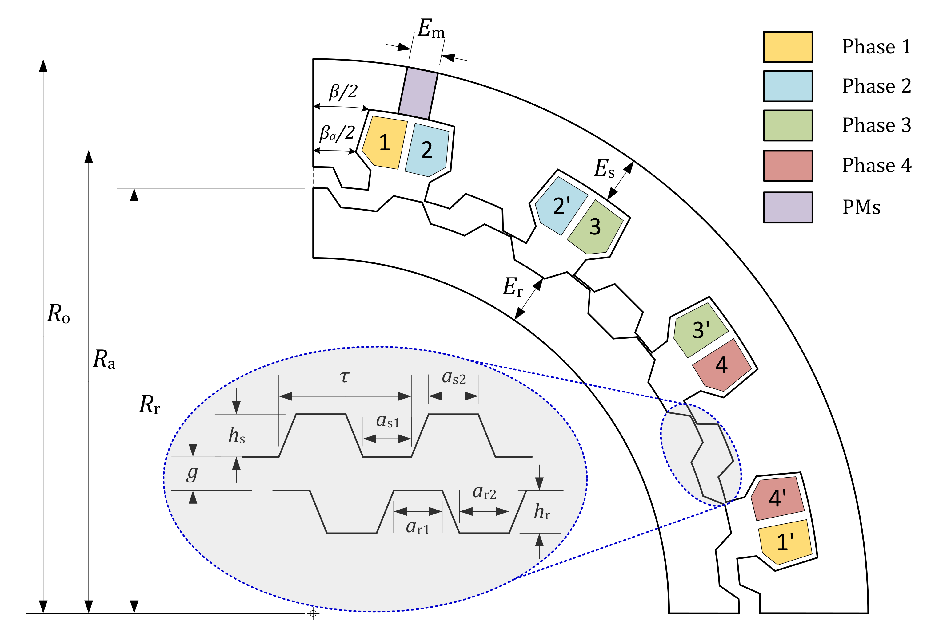
2. Machines Design and Modeling
The 4-phase TDSPM machines are designed under the problem constraints and requirements shown in Table 1. The external volume and the air gap length values are constrained to be the same as in the reference design.
The TDSPM under study are characterized by several integer design parameters which are the number of teeth in the stator (), the number of teeth in the rotor (), the number of statoric salient poles (), the number of rotoric teeth per statoric salient pole (), the number of magnet pairs (), and the number of phases (m) as shown in Figure 1b. In the studied case the statoric tooth step () is identical to that of the rotor (), i.e.:
As has been shown in [,,,,,,], the following set of relations between the design parameters have to be respected:
where , and K must be integers, and:
and K is equal to the maximum number of teeth per statoric pole . If is equal to 1 the machine obtained is similar to that studied in []. These types of machines are more dedicated to high speed applications, and thus this kind of machine is not studied in this work. The specificity of the studied machine compared to other DSPM found in the literature (as the one studied in [,,]) is that it includes large toothed stator poles which allow to increase the number of rotor teeth leading to the increase of the electrical frequency. Indeed, the rotor speed varies inversely with the number of rotor teeth (Equation (5)); this is why this kind of machine can operate at low speed with only a small number of magnets and coils.
The stator pole numbers per phase must be even for magnetic flux symmetry reasons. The number and are chosen so that, when the teeth of a phase are in conjunction, the following phase teeth are shifted of from the rotoric ones. Parameter is defined by Equation (4).
where N is the rotational speed (in rpm).
Considering the relations between these parameters, for the specified rated speed (100 rpm) and desired supply frequency (50 Hz), 2 sets of structural parameters for the 4-phase TDSPM machine with 4 and 2 statoric poles per phase have been determined. These structural parameters are summarized in Table 2. The two structures are presented in Figure 1. It can be noted that considering the chosen rotor teeth numbers (Table 2) and Equation (5), the electrical frequency is 50 Hz and 46.66 Hz for the DSPMs with two coils/phase and four coils/phase, respectively.
Table 2.
Integer design parameters of the studied machines.
The shape of the teeth (in the stator and rotor) for both considered machines is trapezoidal. The shape of the teeth is described in Figure 2 and defined according to the following design parameters:
Figure 2.
Geometric parameters of teeth and statoric salient poles of the studied machines.
- Rotor and stator teeth depth and ;
- Teeth cyclic ratio , , , and .
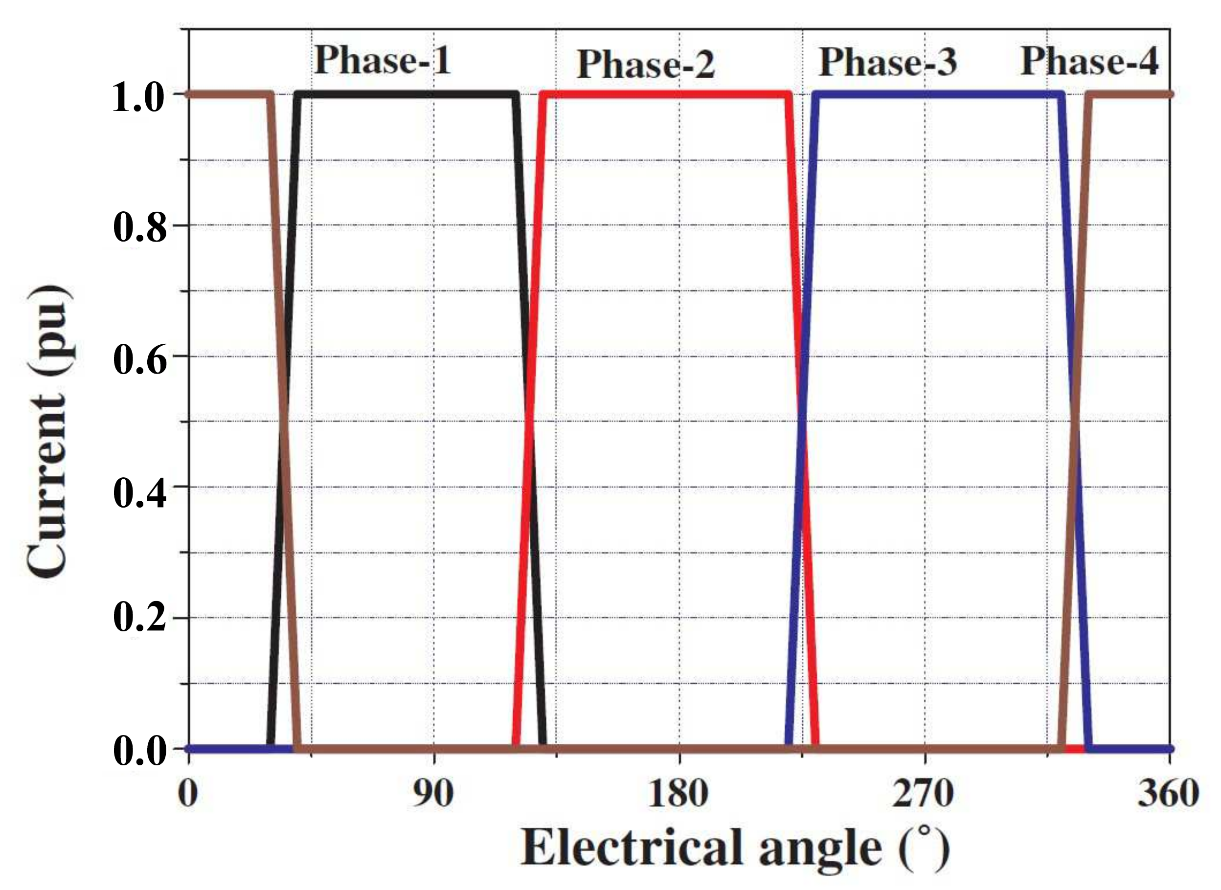
with: ≤ 1, (j = r,s).
The permanent magnets are placed in stator yoke and provides the field excitation. The proposed machines use a double-layer concentrated winding, where each coil is wound around a stator salient pole. Therefore, two layers of windings corresponding to two adjacent phases are located in each stator slot. So the winding of one phase is obtained by connecting two concentrated coils in series or four concentrated coils in series for the first and second studied structures, respectively. The TDSPM machines are considered to be supplied by rectangular current waveforms, where each phase is supplied successively, as shown in Figure 3.
Figure 3.
Current supply strategy of studied machines.
Thus, when the teeth of stator slots of a given phase’s statoric pole are aligned with the teeth of the rotor, the position is designated as conjunction position (in this position, the flux created by the magnets in the phase coils reach a maximum value, Figure 4). When the teeth of stator slots of a given phase are unaligned with the teeth of the rotor, the position is designated as opposition position (in this position, the flux in the phase coils reach a minimum value, Figure 5). Over one electric period, when the rotor moves from opposition position to conjunction position, a positive current is injected into armature coil to produce the same polarity flux with that of PM, thus positive torque is generated. Further, as a combined result of four phase operation (compared to 3-phase machines), more smooth output torque will be generated.
Figure 4.
Conjunction (aligned) position and flux density distribution.
Figure 5.
Opposition (unaligned) position and flux density distribution.
A uniform current density is considered into a supplied half slot (corresponding to a supplied phase), where represents the coil fill factor and the current density in the winding conductors. Thus, the flux in one supplied phase can be expressed as []:
where is the self-inductance of the corresponding stator phase and is the permanent magnet flux.
Soft iron parts (iron cores) are built with mm of M400-50A steel laminations. NdFeB PMs with magnetization, , and relative permeability are used [].
2.1. Average Torque
The mean torque () is calculated by FEA by using Equation (7). The used calculation method is based on virtual work method where the co-energy and the magnetic energy are calculated by FEA []. Figure 6 presents the flux curves versus current ((i)) in one phase for two specific positions of the rotor (conjunction and opposition).
Figure 6.
Flux linkage versus stator phase current.
The current varies from 0 to its rated value (in p.u.). The average torque can be estimated based on the energy cycle (Figure 6) from the knowledge of the co-energy on the two previously defined specific positions (conjunction and opposition) and the magnetic energy as in [,,]:
2.2. EM Calculation Method
In order to evaluate the electromagnetic performance of the proposed structure, Finite Element Analysis (FEA) using FEMM software is used. This method allows to solve the magnetostatic formulation of the Maxwell equation in 2D. For the studied machines, the system to be solved by FEA is expressed as follow.
- In the conductor part
- In the iron part
- In the air gap part
- In the PM part
Dirichlet boundary condition is applied on the external boundary of the domain.
where and are the axial components of magnetic potential vector A and the current density J, respectively. is the equivalent surface current density of the magnet and the magnetic permeability of iron.
As an example the 2D-FEA meshes of a two coils/phase and four coils/phase structure can involve approximately instead of 200,000 nodes for about 400,000 elements and 400,000 nodes for about 800,000 elements, respectively. A refined mesh is used in the air gap for precise calculation of the torque and flux quantities including 2D flux leakages.
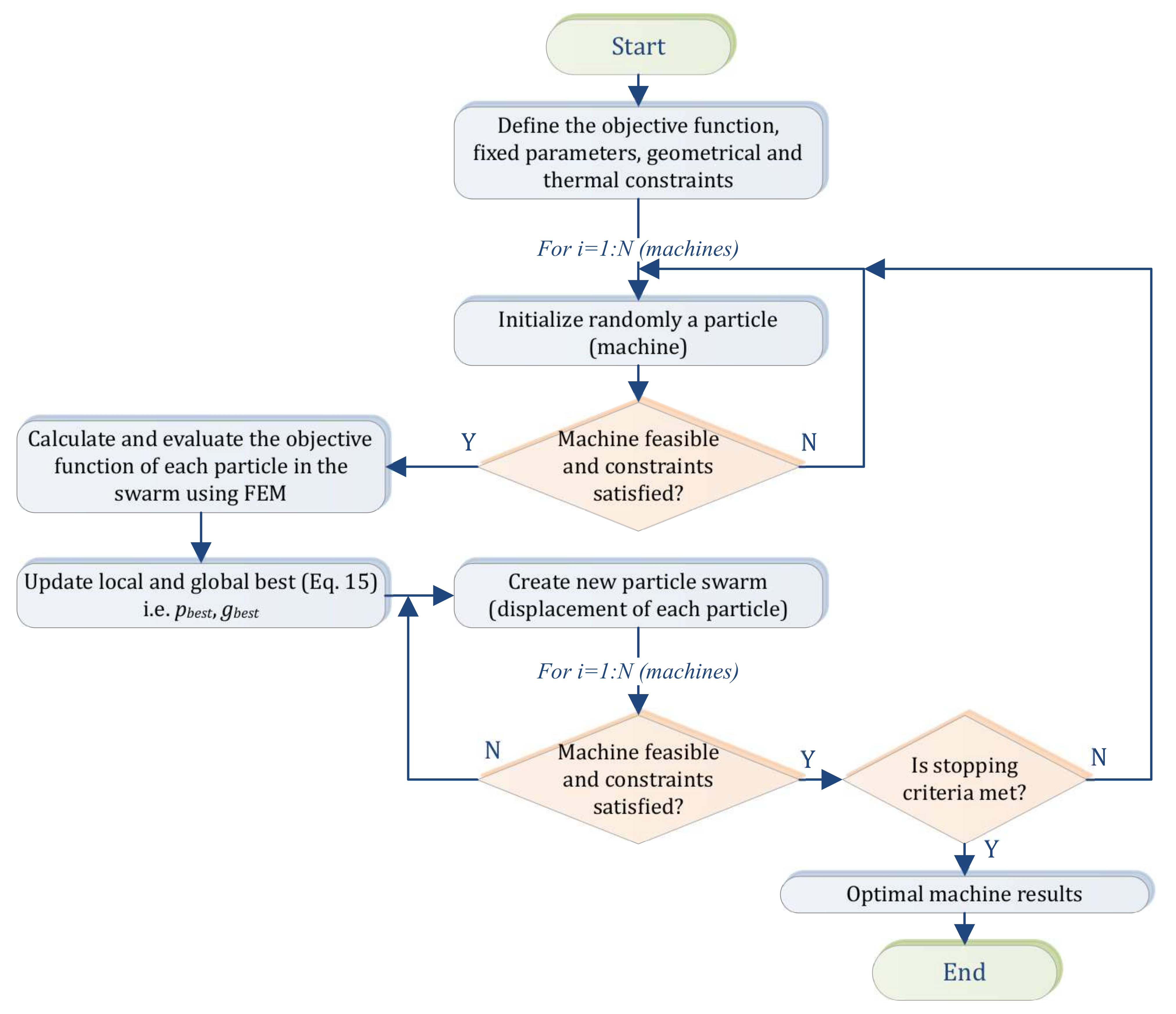
3. Design Process and Optimization
The studied machines achieves the advantages of gearless operation but suffers the drawbacks of bulky size and heavy weight for high torque output. This is why in this work, the torque to mass ratio (Equation (13)) is selected as the objective function to be maximized.
where, M represents the machine’s active mass (sum of the masses of copper, iron, and magnets) and represents the mean torque for one phase supplied by its rated current. All the quantities related to electromagnetic phenomena as torque or energy ratio are determined during and after the optimization process by a FEA using FEMM software as described in Section 2.2.
PSO optimization process coupled with finite element method (FEM) is applied to determine the optimal design of the 4-phase TDSPM machines to maximize the mass-to-torque ratio. Maximizing the mass-to-torque ratio accounts for maximizing the electromagnetic torque while minimizing the active mass of the machine and therefore the size and cost.
The structures are designed for the same specification set used for the machine studied in [] proposed for a high power ship propulsion realistic design (Table 1). The specification set is characterized by a mechanical power of 2 MW at 100 rpm and a rated torque of 191 kNm.
The proposed TDSPM motors have the same external volume and use the same material characteristics (magnets, iron, and copper) and physical parameters. The global design for the two configurations of machines is defined with the parameters given in (Figure 2) and presented in Table 3 which are the optimization search variables (vector x ). The optimization variables and their variation ranges are given in Table 3.
Table 3.
Design variables and respective ranges.
The thermal exchanges with the environment and with the core of the machine are extremely complex. However, as a first approximation, it is possible to take into account the concept of a heating product (Equation (15)), which only applies to individual Joule losses in stator armatures [,,].
Moreover, the studied machines are designed for a thermal product (Equation (15)) equal or better than the one given in Table 1. Indeed, a very basic thermal steady state of the machine is used where the only thermal resistance to be considered is related to convection heat transfer in the external surface of the stator (other thermal resistances are neglected). This resistance is considered by using a fixed coefficients of convection h, on this stator surface S. This model is described by Equation (14). It is also assumed that the external radius of the machine is close to the internal radius of the stator and that, the internal radius value can be used to approximate the external surface where the convection phenomenon is located (last relationship of Equation (14)) [,,,].
where , and S, respectively, represent the resistivity, the volume of the copper and the surface area of exchange by convection. From Equation (14), it can then be demonstrated that,
The thermal product is defined as the product of the linear current density and the current density J (A/m). The linear current density (A/m) is given as [,]:
is the number of conductors per phase carrying a RMS current I, m is the number of phases and is the inner stator radius. The latter is given as:
where , , , are defined in Table 3 and Figure 2.
The current density is considered also as a variable of optimization. It is varied from 1 A/mm to 15 A/mm. For each structure, the thermal product is calculated and compared with those of the reference machine [] to check that the thermal behaviour of the proposed structure is acceptable. Considering all these hypotheses, the optimization problem can be formulated as follows:
The imposed constraints are given by:
Summarizing, the search variable along with their lower and upper limits are shown in Table 3.
Complementary geometrical constraints are introduced in the PSO algorithm corresponding to the machines design. These constraints are related to the feasibility of the structure and the respect of the external volume constraint. Analytically, for a fixed external volume, the lower limit of the inner rotor radius is , and it leads to introduce the following constraint: ≥ , where is the outer rotor radius. When the thickness of the rotor and the depth of rotor teeth varies, the calculated inner rotor must be higher than and must be lower than the outer rotor radius limit, to keep the machine design feasible and practicable.
The upper limit of the angles and is . is number of statoric pole. For DSPM with four coils per phase, = 16 pole. So, the upper value of the slot and pole opening angle is 180/16 = 11.5. A larger value result in overlapping a stator pole on the adjacent stator pole and the non feasibility of the structure.
An evaluation of the geometric parameters to determine the geometric feasibility (feasibility test) is performed within the optimization algorithm, for each candidate (set of parameters) element. This test allows avoiding study of geometrically impossible solutions. If the with the dimensions is feasible, the calculation of output performance data is performed using finite element method. Otherwise, all the parameters are initialized at random again until the geometric feasibility is achieved.
The developed PSO algorithm combined with FEMM software can be summarized as follows: The particle updates, in every iteration, its “velocity” and “position” with the following equations [,]:
where:
: is the current position;
: is the velocity;
: is the best solution (fitness values achieved for each particle);
: is the best value tracked by the particle swarm optimizer;
: is the coefficient of constriction. The latter is given by:
where is the confidence coefficient = 4.1;
and : are the acceleration coefficients which, in turn, are calculated as follows:
From the PSO algorithm flowchart (Figure 7), when the local (pbest) and and global best are updated, a generation of machines has been determined. The best machine is selected (the one with the best objective function) and the average value of the objective functions of all the elements of the population is calculated. The two results are recorded each time. These two values are then used to plot for for example Figure 8a,b. If they no longer change as the number of generations increases, the optimum can be considered as reached.
Figure 7.
PSO algorithm flowchart (see also Appendix A).
Figure 8.
Objective function and torque evolution as a function of generations number: (a) TDSPM with two coils/phase structures, (b) TDSPM with four coils/phase structures.
In the test steps of the algorithm, if the machine geometry is not feasible or if the thermal constraint related to thermal product is not satisfied then the algorithm selects a new machine to be evaluated. A more detailed description of the PSO algorithm is given in Appendix A.
4. Results and Discussion
A low swarm number size reduces the computational time but the algorithm may converge to a local minimum. A compromise is done with 50 machines (swarm) and 50 generations which represents arround 15 hours of calculation for the used computer configuration processor: Intel(R) Core(TM) 2.30 GHz. The PSO tuning parameters used are []: = 4.1; = 0.7298; ∈ [0, 2.05].
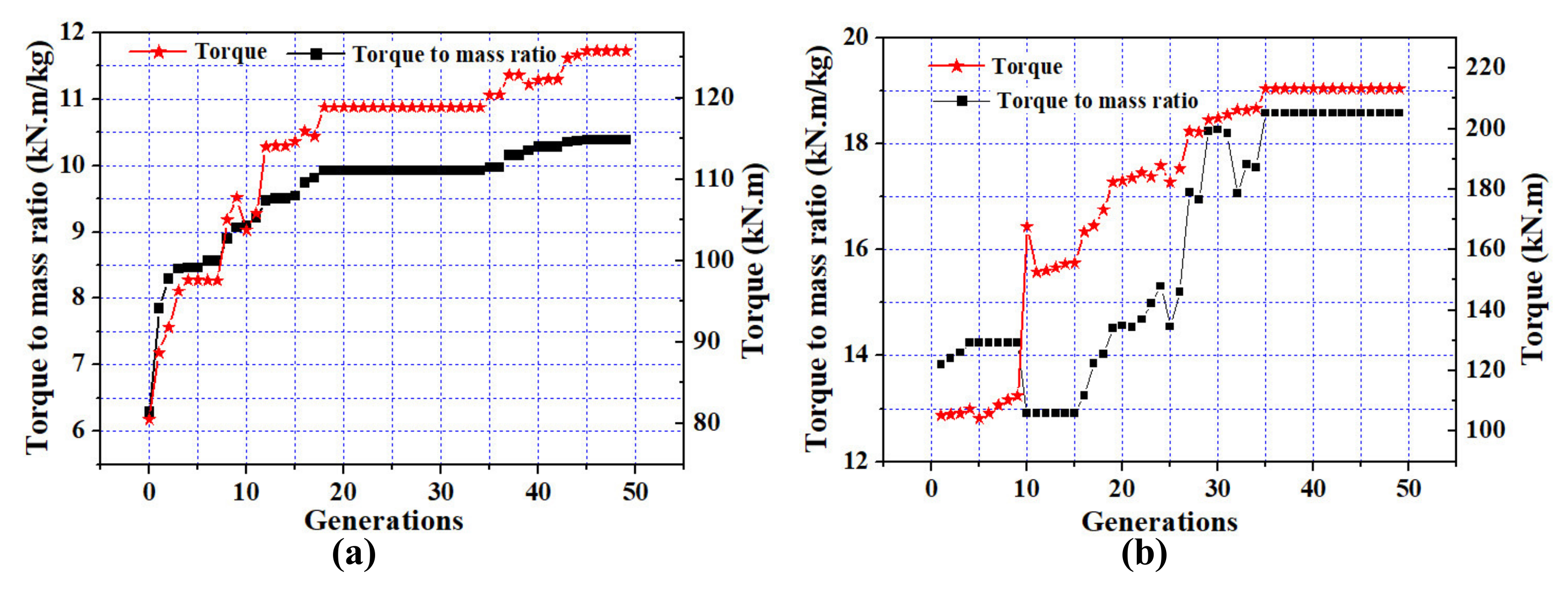
4.1. Objective Function and Torque Evolution
The evolution of the mass to torque ratio and the average torque for the two 4-phase TDSPM versus generation number are shown in Figure 8. Table 4 presents the optimal results obtained for the two structures under investigation. Table 5 summarizes the corresponding performance criteria.
Table 4.
Optimal search variables values.
Table 5.
Otpimal torque, torque ripple and energy ratio found.
The optimal solution is achieved at the 42nd generation for the 4-phase TDSPM with two coils/phase structure, and at the 35th generation for the 4-phase TDSPM with four coils/phase structure. It can be seen from Figure 8 that the convergence to the optimal design which satisfying all the applied constraints is obtained successfully by the adopted algorithm. That means that the algorithm explores and exploits a large search space in order to converge towards the global optimum.
It should be noted that, the results obtained by PSO, in both machines, have been validated by applying also an optimisation by genetic algorithm (not presented in this work). The two algorithms converge towards the same optimum. This result confirms that the objective function of the optimal structures obtained by PSO is the global optimum.
From the results of Table 5, for the same external volume in both machines and considering the specifications given in Table 1, it can be observed that the desired rated torque is achieved in the TDSPM structure with four coils/phase. However, for the DSPM using two coils/phase it can be noted that the required torque of 190 kNm is not met for the TDSPM with two coils/phase. That can be explained because the thermal constraint does not allow to reach a sufficient current density in the slot to reach this requirement.
The mean torque of the TDSPM structure with four coils/phase is 48% greater then that with two coils/phase, and the mass to torque ratio is about 40% greater than those with two coils/phase.
The torque ripple value of the TDSPM motor with four coils/phase is around 37% smaller then that of two coils/phase. It can be noted that the torque ripple is mainly caused by the stator and rotor saliency and current commutation. Even if these results appears very promissive further investigations can be done in future works particularly in terms of torque ripple reduction.
The results of Table 5 revealed also that, the energy ratio in the TDSPM with four coils per phase is around 11% greater than that in two coils/phase structure. However, it turns out that the energy ratio is a little low in the two structures compared to the PM synchrounous machines, and impact directly in the converter sizing. However, this relatively low energy ratio is compensated by the simplicity and the compactness of the machine.
Considering all these factors, it seems that the performance of the 4-phase TDSPM with four coils per phase configuration is greater than those with two coils/phase.
4.2. Efficiency
The efficiency of the studied machines is estimated by taking into account the Joule losses and the iron losses. The Joule losses in the DSPM under study are estimated by:
where and are the resistance and RMS current of phase i. The phase RMS currents are calculated using the waveforms of Figure 3. The phase resistance includes estimation of the resistance of the conductors in the slots and in the end-windings [].
The Joule losses values, are 90.6 kW and 102.10 kW for two coils per phase and four coils per phase structures, respectively. Thanks to the particular principle of the studied machines, it can be noted that the flux density vary slightly in the iron cores (the flux variation in the iron parts is mainly related to the variation of reluctance due to alignement and disalignement of small teethes). The variations of magnetic flux density in the different iron parts of the structures are evaluated using FEA (FEMM software). Local and global iron losses in the two optimal structures are evaluated from these flux density variation values using classical Bertotti formula [] and the knowledge of the information supplied by the used M400-50A electrical lamination manufacturer data sheet. This rought evaluation of global iron losses shows that the iron losses are very small (less than 7kW for the 2 optimal structures) in front of Joule losses and can be in first order neglected in the efficiency estimation. The efficiency estimation leads to efficiency values of about 95 percent for the both structures. These values are of the same level as for classical huge power motors used in naval propulsion [].
4.3. Basic Characteristics and Performance Comparison
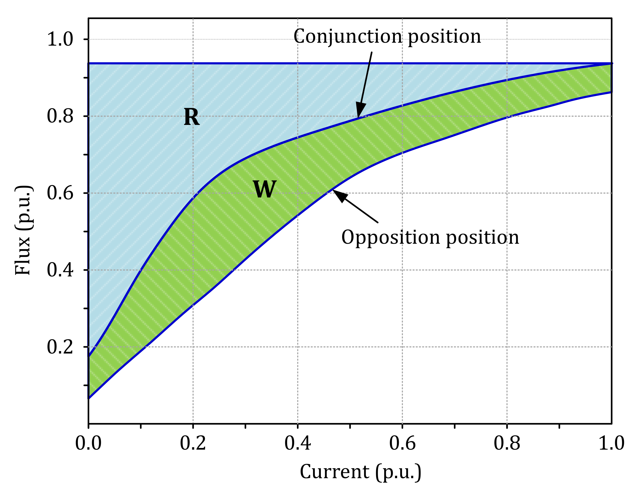
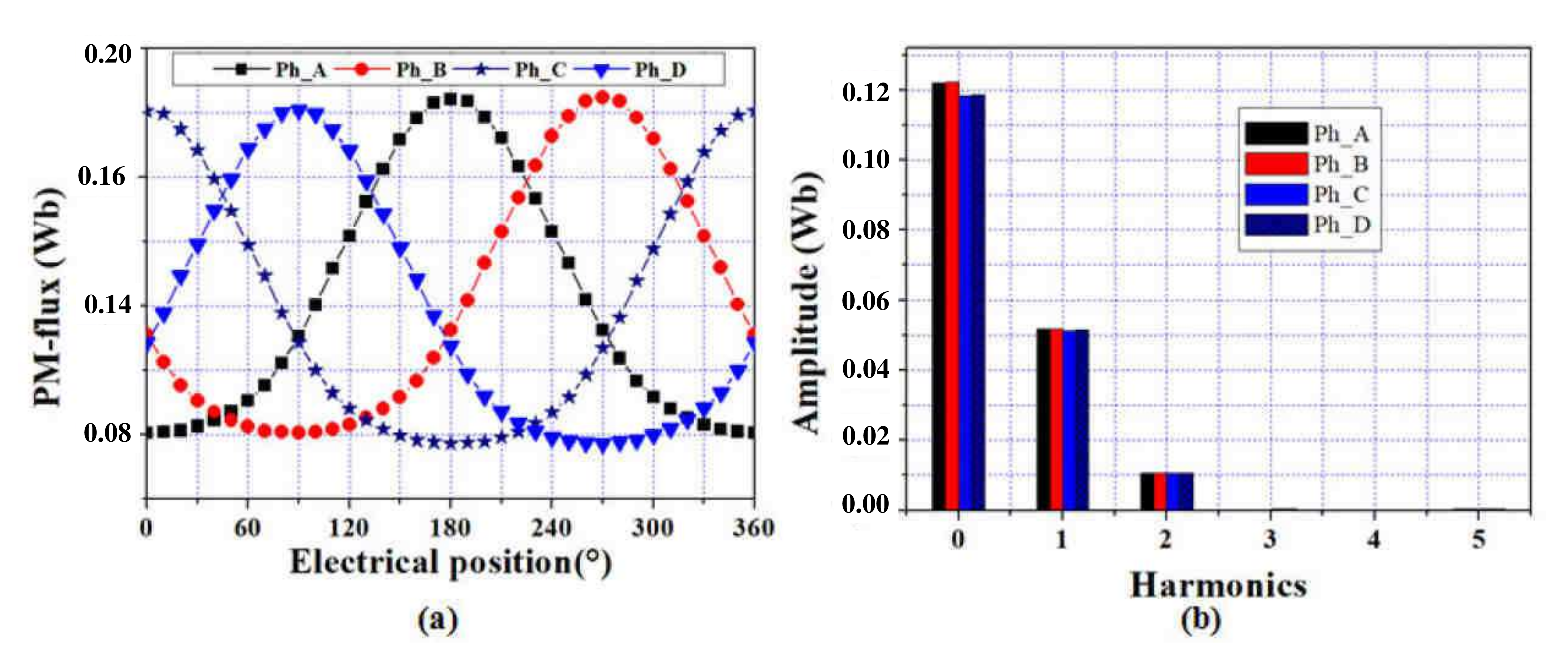
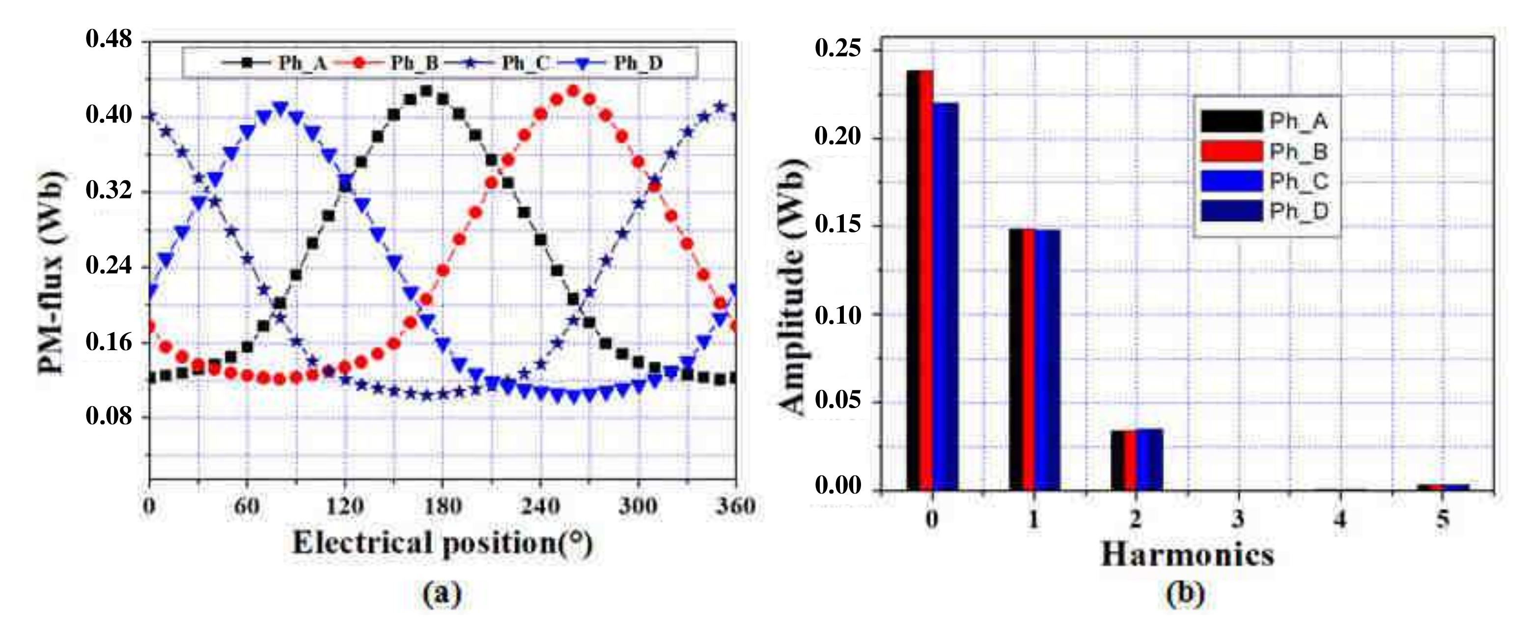
In order to determine and evalute the static characteristics and performance of the studied machine, finite element method analysis (carried under the open source FEMM software) is used to calculate the magnetic field density distribution in the machine air gap, PM-flux, electromagnetic torque and energy ratio.
4.3.1. PM-Flux
PM flux of the 4-phase with four coils/phase and two coils/phase of optimal machines, are given in Figure 9 and Figure 10 for per phase. As shown in Figure 9 and Figure 10, in both machines, the 4-phase PM-flux linkages are unipolar. The average value of 4-phase with four coils/phase ( Wb) is much larger than that in 4-phase machine with two coils/phase TDSPM (0.14 Wb). Besides that, according to the spectra of phase PM flux, in both machines, the DC-bias values (continuous harmonic components) of phase A and B PM-flux are about higher than phase C and D, which is due to the location of phases B and C that are away from the location of permanent magnets.
Figure 9.
PM-flux and FFT spectra of 4-phase with two coils/phase: (a) PM-flux, (b) FFT spectra.
Figure 10.
PM-flux and FFT spectra of 4-phase with four coils/phase: (a) PM-flux, (b) FFT spectra.
In addition, the total harmonic distortion (THD) of 4-poles TDSPM is relatively smaller compared to 2-poles TDSPM mainly due to the larger fundamental and smaller 2nd harmonic components.
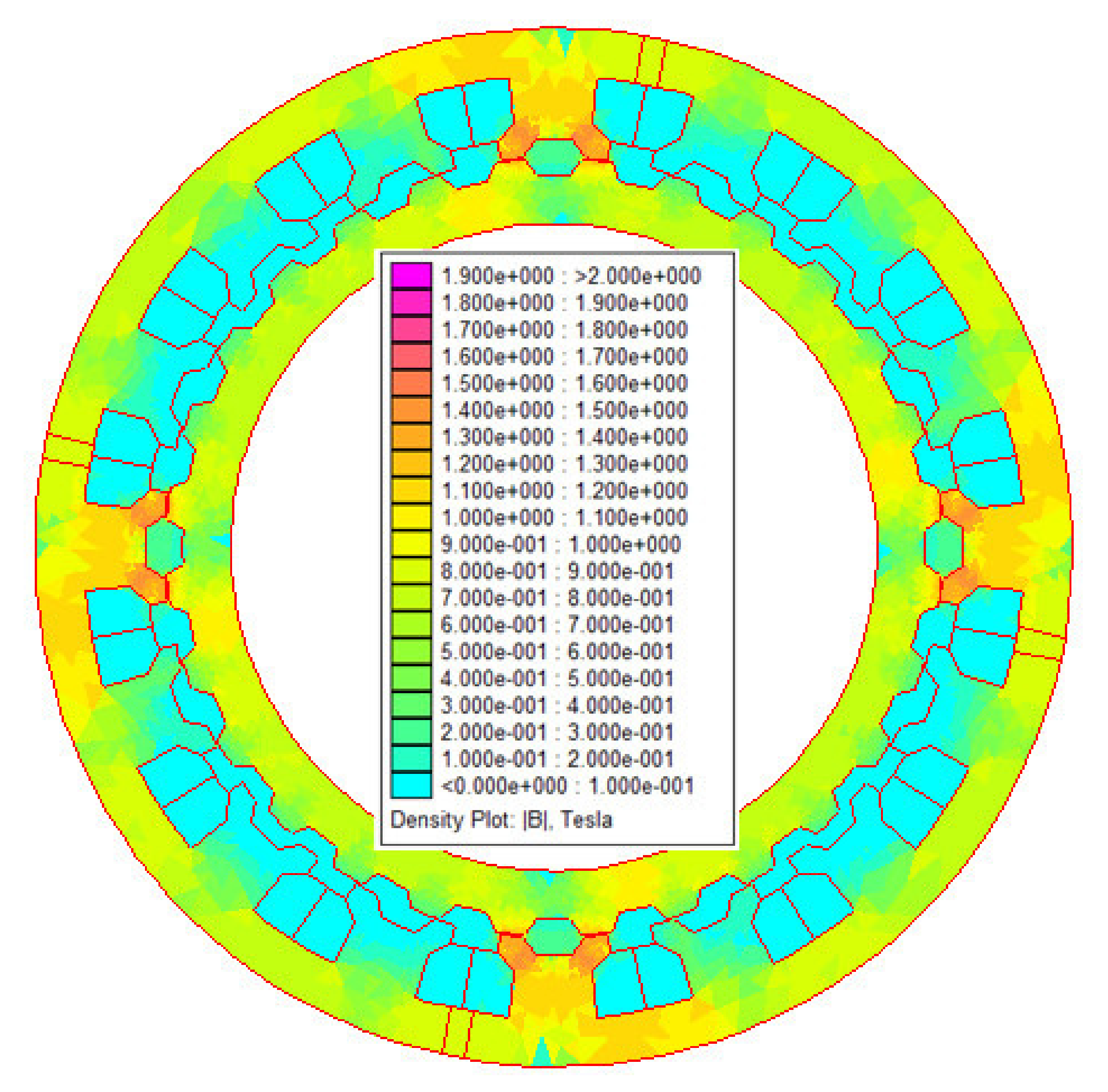
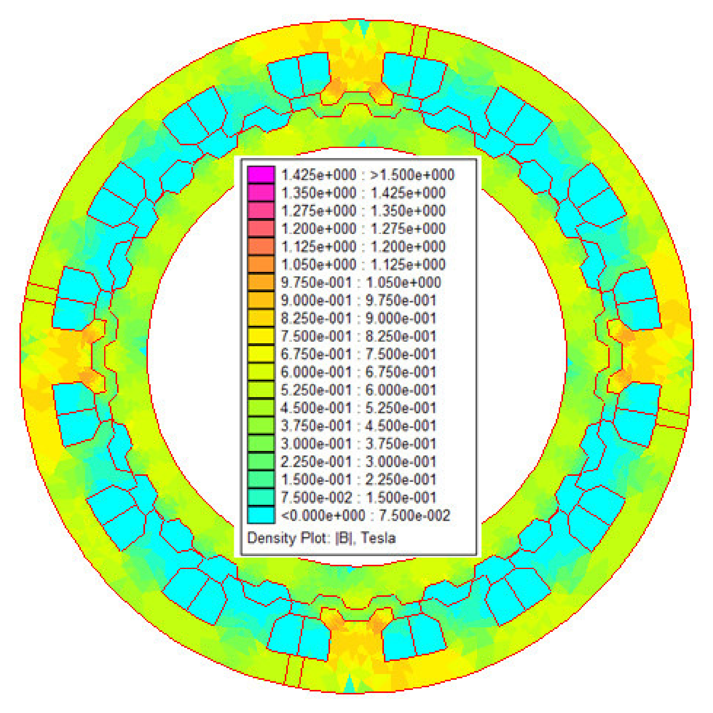
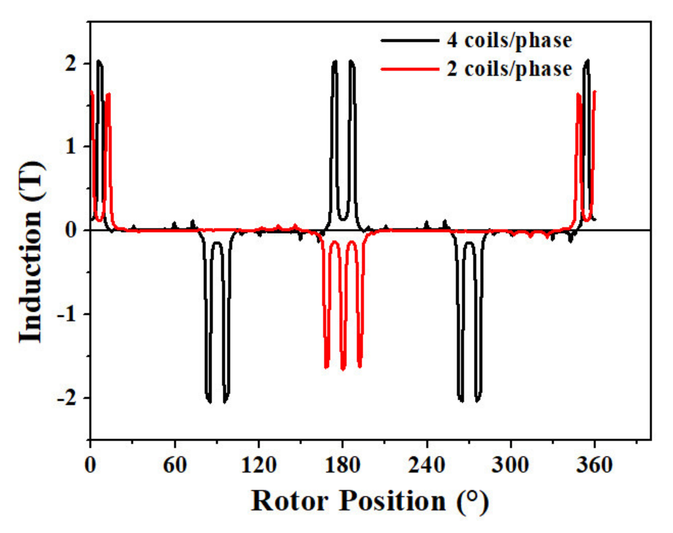
4.3.2. Air-Gap Flux Density
The air gap flux density distributions along the radial directions of the optimal 4-phase TDSPM structures (in conjunction position), under rated load conditions are presented in Figure 11.
Figure 11.
Air-gap flux density of 4-phase TDSPM with 2 and four coils/phase optimal structures versus rotor position.
In both machines, the air gap flux density is mainly influenced by the pole saliency of the stator and rotor. Therefore, the air gap flux-density distributions, in the studied machine, are far from sinusoidal and contain significant harmonics. The peak air gap flux density under the stator pole is about and about (Figure 11) for two coils /phase and four coils per phase structures, respectively.
This difference is due to the stator and rotor yoke thikness and the number of permanent magnet which are not the same in the two structures. It leads to a significant iron magnetic saturation of 4-phase TDSPM with four coils per phase. However, the higher flux density leads to a higher torque density, so among the two machines, the 4-phase TDSPM with four coils per phase have the potential to produce the better performances.
4.3.3. Ripple Torque and Energy Ratio
In order to estimate the rated power of the converter in comparison with the rated power of the motor, and evaluate the impact of the machine design on the converter sizing, the energy ratio is used in this work. This factor is proposed for variable speed switched reluctance motors by [,,], defined as:
From Figure 6, the area represents the total energy exchanged between the machine and the power converter. The area between the opposition position and conjunction position curves represents the maximum energy available for electromechanical conversion. In real operation, only a part of this energy can be converted.
The proposed motors are compared in terms of relative torque ripple defined as:
where , and are, respectively: the average torque value, the minimum torque and the maximum torque. Calculated performance data are reported in Table 5.
According to the obtained results of Table 5, 4-phase TDSPM machine with four coils reaches an energy ratio of and 4-phase TDSPM machine with two coils reaches an energy ratio of . In consequence, the 4-phase TDSPM machine with four coils/phase requires lower rated power for the static converter.
The performance data reported in Table 5 indicated also that, 4-phase TDSPM machine with four coils/phase products an average torque (190 kN.m) similar to the torque produced by reference machine (PMSM) presented in [] and a torque ripple of . The 4-phase TDSPM machine with two coils/phase product an average torque lower than reference PMSM (100 kN.m) and a torque ripple of . This means that, the increase in the number of coils/phase in multiphase toothed doubly salient permanent magnet structures leads to a strong improvement in terms of torque value, torque quality and energy ratio .
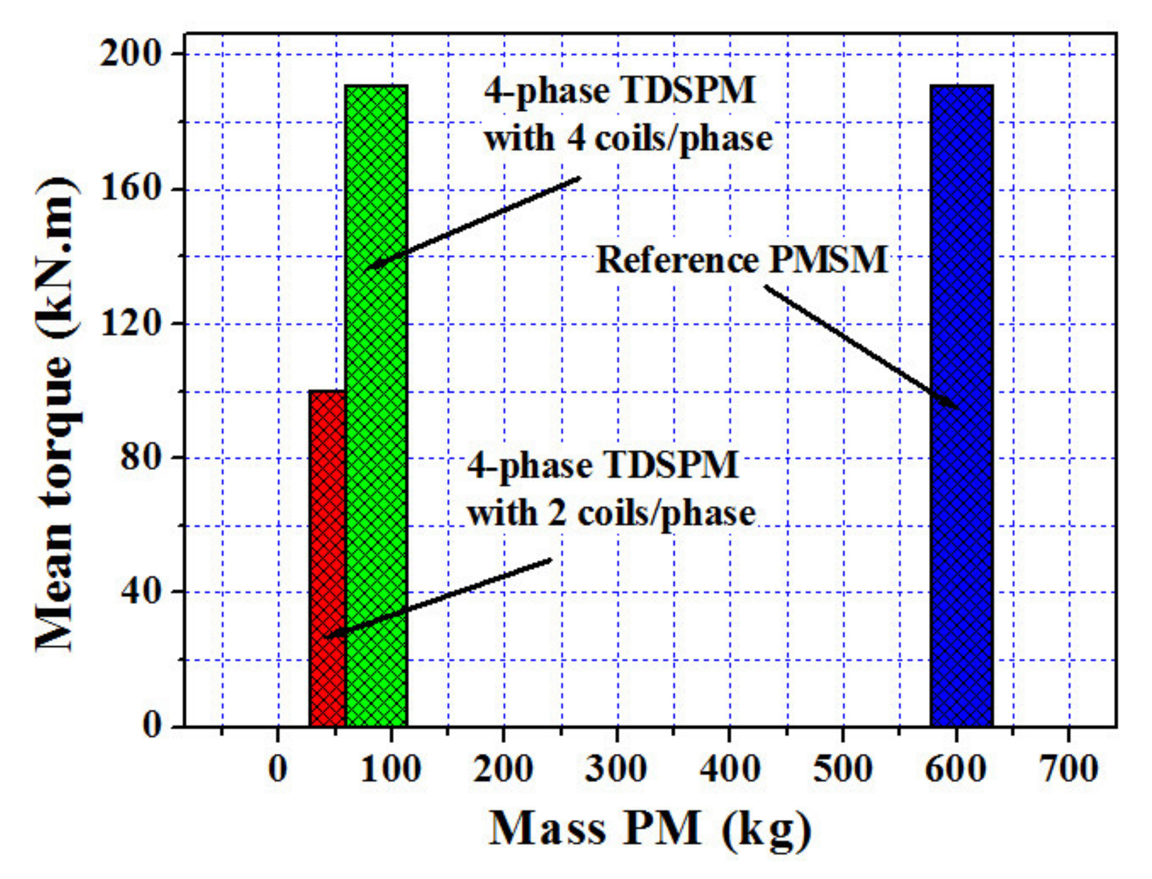
5. Comparison with Reference PMSM
The studied machines PM mass are compared with classical PMSPM (reference machine). The PM mass used in the three machines and their mean torques are presented in Figure 12. The results obtained reveal that the 4-phase TDSPM with four coils/phase machines appear to be significantly more interesting than the reference PM synchronous machine in terms of magnet mass (and so probably in terms of global active material cost). The PM masses are about 83% less than those of the reference PMSM. For the same volume as PMSM, the proposed machine with four coils per phase can achieve the performance of conventional synchronous machine (rated torque and output power) at a low cost.
Figure 12.
PM-mass comparison.
6. Conclusions
In this paper, the performances of novel 4-phase toothed doubly salient synchronous PM machines with two and four coils/phase have been investigated using an optimal design process based on particle swarm optimization. In this optimization process, a 2D FE method is used to evaluate the objective function which is torque to mass ratio. The designs are processed for the same overall dimensions, material caracteristics and thermal behavior, according to a reference classical PM synchronous machine designed in the literature for direct drive high power naval propulsion. The obtained results demonstrate that a 4-phase TDSPM with four coils/phase can a very interesting option for this application. The 4-phase toothed doubly salient permanent magnet structure with two coils/phase did not reach the design requirements in terms of rated torque. The obtained structure with four coils/phase reaches the performances in terms of torque of the reference machine with a very lower magnet mass, limited torque ripple and limited converter oversizing.
Even if these results appear very promising, further investigations can be done in future works, particularly in terms of torque ripple reduction.
Author Contributions
Conceptualization, Methodology, C.G., J.-F.C., R.S., Y.L.K.; software, validation, C.G.; Formal Analysis, Draft Preparation, Writing, Review, and Editing, C.G., J.-F.C., R.S., Y.L.K., N.B., M.E.-H.Z.; All authors have read and agreed to the published version of the manuscript.
Funding
This research received no external funding.
Institutional Review Board Statement
Not applicable.
Informed Consent Statement
Not applicable.
Data Availability Statement
Not applicable.
Conflicts of Interest
The authors declare no conflict of interest.
Appendix A
The optimization problem is written in the form of a Lua script program which is associated to FEMM software for the finite element electromagnetic analysis. The optimization procedure based on PSO method is given in Figure 7 ( PSO algorithm flowchart) is devopped as follows:
- Define the objective function, fixed parameters, geometrical and thermal constraints.
- For i = 1: N do
- (a)
- Initialize randomly a particle (machine).
- (b)
- If machine is not feasible or thermal constraints is not satisfied return to step 2a.
- (c)
- End
- Calculate and evaluate the objective function of each particle in the swarm using FEMM software (2D-FEA)
- Update local and global best (pbest and gbest )
- For i = 1: N do
- (a)
- Produce new particle (displacement of each particle) using (15)
- (b)
- If machine is not feasible or thermal constraints are not satisfied return to step 5a.
- (c)
- End
- Check if the stop criterion is satisfied; if not return to step 3.
- Output optimal results.
- Stop.
In the step 2(b) and (5b) which specifies that if the machine is not geometrically feasible or if the thermal constraint is not satisfied, the algorithm go back to step 2a (or 5(a)). In this steps, an evaluation of the geometric constraints to determine the geometric feasibility (feasibility test) is performed within the optimization algorithm, for each candidate (set of parameters) element. This test allows avoiding study of geometrically impossible solutions. If the with the dimensions is feasible and the thermal constraint is satisfied, the calculation of output performance data is performed using finite element method. Otherwise, all the parameters are initialized at random again until the geometric feasibility is achieved.
In this step 5(a), a generation of machines has been determined. The best machine is selected (the one with the best objective function) and the average value of the objective function for all the elements of the population is calculated. The 2 results are recorded each time. These 2 values are then used to draw for example Figure 8a,b.
References
- Thongam, J.S.; Tarbouchi, M.; Okou, A.F.; Bouchard, D.; Beguenane, R. Trends in naval ship propulsion drive motor technology. In Proceedings of the 2013 IEEE Electrical Power &Energy Conference, Halifax, NS, Canada, 21–23 August 2013; pp. 1–5. [Google Scholar] [CrossRef]
- Karnavas, Y.L.; Chasiotis, I.D.; Pechlivanidou, M.S.C.; Karamanis, E.K.; Kladas, A.G. Azimuth Thruster PMSM Optimization using Symbiotic Organisms Search Algorithm. In Proceedings of the 2020 International Conference on Electrical Machines (ICEM), Göthenburg, Sweden, 23–26 August 2020; Volume 1, pp. 2231–2237. [Google Scholar] [CrossRef]
- Lateb, R.; Takorabet, N.; Meibody-Tabar, F.; Mirzaian, A.; Enon, J.; Sarribouette, A. Performances comparison of induction motors and surface mounted PM motor for POD marine propulsion. In Proceedings of the Fourtieth IAS Annual Meeting, Conference Record of the 2005 Industry Applications Conference, Hong Kong, China, 2–6 October 2005; pp. 1342–1349. [Google Scholar] [CrossRef]
- Scuiller, F.; Semail, E.; Charpentier, J.-F.; Letellier, P. Multi-criteria-based design approach of multi-phase permanent magnet low-speed synchronous machines. IET Electr. Power Appl. 2009, 3, 102–110. [Google Scholar] [CrossRef] [Green Version]
- Saou, R.; Zaïm, M.E.H.; Alitouche, K. Optimal Designs and Comparison of the Doubly Salient Permanent Magnet Machine and Flux-reversal Machine in Low-speed Applications. Electr. Power Components Syst. 2008, 36, 914–931. [Google Scholar] [CrossRef]
- Guerroudj, C.; Saou, R.; Boulayoune, A.; El-hadi Zaïm, M.; Moreau, L. Performance Analysis of Vernier Slotted Doubly Salient Permanent Magnet Generator for Wind Power. Int. J. Hydrog. Energy 2017, 42, 8744–8755. [Google Scholar] [CrossRef]
- Bekhouche, L.; Saou, R.; Guerroudj, C.; Kouzou, A.; Zaïm, M.E.H. Electromagnetic Torque Ripple Minimization of Slotted Doubly-Salient-Permanent-Magnet Generator for Wind Turbine Applications. Prog. Electromagn. Res. M 2019, 83, 181–190. [Google Scholar] [CrossRef] [Green Version]
- Guerroudj, C.; Zaïm, M.E.H.; Bekhouche, L.; Saou, R.; RAMELI, A. Comparison of Outer and Inner-Rotor toothed Doubly Salient Permanent Magnet Machine. In Proceedings of the 19th International Symposium on Electromagnetic Fields in Mechatronics, Electrical and Electronic Engineering (ISEF), Nancy, France, 29–31 August 2019; pp. 1–2. [Google Scholar] [CrossRef]
- Guerroudj, C.; Karnavas, Y.L.; Charpentier, J.-F.; Chasiotis, I.D.; Bekhouche, L.; Saou, R.; Zaïm, M.E.-H. Design Optimization of Outer Rotor Toothed Doubly Salient Permanent Magnet Generator Using Symbiotic Organisms Search Algorithm. Energies 2021, 14, 2055. [Google Scholar] [CrossRef]
- Rezzoug, A.; Zaïm, M.E.H. Non-Conventional Electrical Machines; John Wiley & Sons Inc.: Hoboken, NJ, USA, 2011. [Google Scholar]
- Guerroudj, C.; Boulayoune, A.; Saou, R.; Zaïm, M.E.H.; Moreau, L. Study of Vernier effect on the EMF of a slotted DSPM generator for wind power applications. In Proceedings of the Conference Internationale des Energies Renouvelables, Sousse, Tunisia, 19–21 December 2015. [Google Scholar]
- Guerroudj, C.; Saou, R.; Charpentier, J.F.; Boulayoune, A. Optimal Design of a Novel Doubly Salient Permanent Magnet Motors for High Power Ship Propulsion. In Proceedings of the 2018 XXIII International Conference on Electrical Machines (ICEM), Alexandroupoli, Greece, 3–6 September 2018; pp. 2556–2562. [Google Scholar] [CrossRef]
- Pechlivanidou, M.C.; Chasiotis, I.D.; Karnavas, Y.L. A Comparative Study on 2D and 3D Magnetic Field Analysis of Permanent Magnet Synchronous Motor using FEM Simulations. J. Electromagn. Waves Appl. 2019, 33, 2215–2241. [Google Scholar] [CrossRef]
- Karnavas, Y.L.; Chasiotis, I.D.; Korkas, C.D.; Amoutzidis, S.K. Modelling and Multi-Objective Optimization Analysis of a Permanent Magnet Synchronous Motor Design. Int. J. Numer. Model. Electron. Netw. Devices Fields 2017, 30, e2232. [Google Scholar] [CrossRef]
- Chasiotis, I.D.; Karnavas, Y.L. A Generic Multi-Criteria Design Approach Toward High Power Density and Fault-Tolerant Low-Speed PMSM for Pod Applications. IEEE Trans. Transp. Electrif. 2019, 5, 356–370. [Google Scholar] [CrossRef]
- Symington, W.P.; Belle, A.; Nguyen, H.D.; Binns, J.R. Emerging technologies in marine electric propulsion. Proc. Inst. Mech. Eng. Part J. Eng. Marit. Environ. 2016, 230, 187–198. [Google Scholar] [CrossRef]
- McCoy, T.J.; Amy, J.V. The state-of-the-art of integrated electric power and propulsion systems and technologies on ships. In Proceedings of the 2009 IEEE Electric Ship Technologies Symposium, Baltimore, MD, USA, 20–22 April 2009; pp. 340–344. [Google Scholar] [CrossRef]
- Kirtley, K.; James, L.; Banerjee, A.; Englebretson, S. Motors for ship propulsion. Proc. IEEE. 2015, 2320–2332. [Google Scholar] [CrossRef]
- Sargos, F.M.; Zaskalicky, P.; Gudefin, E.J. Generalized theory of the structures of reluctance step motors. In Proceedings of the Conference Record of the 1993 IEEE Industry Applications Conference Twenty-Eighth IAS Annual Meeting, Toronto, ON, Canada, 2–8 October 1993; pp. 211–216. [Google Scholar] [CrossRef]
- Fan, Y.; Chau, K.T.; Cheng, M. A new three-phase doubly salient permanent magnet machine for wind power generation. IEEE Trans. Ind. Appl. 2006, 42, 53–60. [Google Scholar] [CrossRef] [Green Version]
- Boldea, I.; Tutelea, L. Reluctance Electric Machines: Design and Control; Taylor & Francis Group: New York, NY, USA, 2018. [Google Scholar]
- Hendershot, J.R.; Miller, T.; John, E. Design of Brushless Permanent-Magnet Machines; JMotor Design Books: Venice, FL, USA, 2010. [Google Scholar]
- Pyrhönen, J.; Jokinen, T.; Hrabovcová, V. Design of Rotating Electrical Machines, 2nd ed.; John Wiley & Sons Ltd.: Flatbush, NY, USA, 2014. [Google Scholar]
- Clerc, M.; Kennedy, J. The particle swarm-explosion, stability, and convergence in a multidimensional complex space. IEEE Trans. Evol. Comput. 2002, 6, 58–73. [Google Scholar] [CrossRef] [Green Version]
- Boulayoune, A.; Guerroudj, C.; Saou, R.; Zaïm, M.E.H. Optimisation par Algorithme génétique et Essaim de particule d une machine a inversion de Flux dédiée à l’éolien. Rev. Roum. Sci. Techn. Électrotechn. et Énerg 2017, 62, 19–24. [Google Scholar]
- Bertotti, G. Physical interpretation of eddy current losses in ferromagnetic materials. I. Theoretical considerations. J. Appl. Phys. 1985, 57, 2110–2117. [Google Scholar] [CrossRef]
Publisher’s Note: MDPI stays neutral with regard to jurisdictional claims in published maps and institutional affiliations. |
© 2021 by the authors. Licensee MDPI, Basel, Switzerland. This article is an open access article distributed under the terms and conditions of the Creative Commons Attribution (CC BY) license (https://creativecommons.org/licenses/by/4.0/).