Abstract
Slewing bearing is a rotating component with high load-carrying capacity, which is an important part of the crane connecting the upper rotating parts and the lower supporting parts; therefore, it is of great significance to analyze the performance of slewing bearings. This paper establishes a theoretical model and an integrated finite element model for the mechanical performance of slewing bearings, and the results of the two show high consistency. The influences of four bearing parameters (contact angle, raceway curvature radius coefficient, rolling element diameter, and number of rolling elements) and three bolt parameters (number of bolts, bolt preload, and washer thickness) on the mechanical performance of the slewing bearing were studied, aiming to provide a reference basis for the selection and design of crane slewing bearings.
1. Introduction
Industrial equipment is developing towards large-scale and heavy-duty integration. To ensure the safe operation of the equipment, transmission components should be capable of simultaneously withstanding axial force, radial force and overturning moment. Due to its strong load-carrying capacity, slewing bearings are widely used in metallurgical equipment, lifting and transportation equipment, wind power generation equipment and aerospace equipment, etc. [1]. The early failure forms of bearings mainly include plastic deformation, wear, corrosion and fatigue, among which the majority of failures are mainly caused by contact fatigue [2]. Therefore, it is of great significance to study the contact characteristics of bearings.
To study the load distribution and load-carrying capacity of slewing bearings, many scholars have conducted extensive research. Wang Hong et al. [3,4,5], based on the special structural form and actual load conditions of slewing bearings and taking the Hertz elastic contact theory as the foundation, obtained the theoretical formula for checking the contact strength of slewing bearings and the drawing methods for dynamic and static load capacity curves. The contact strength calculation and static load curve drawing of the four-point contact ball slewing bearing, the ball-cylindrical roller combined slewing bearing and the multi-row roller slewing bearing were respectively carried out. Qiao Shuguang et al. [6] established the balance equation of force and moment of the ball and column combined slewing bearing under the combined action of multiple loads from the perspective of the relationship between rolling elements and deformation, which is significantly different from the simplified method. They also conducted strength calculations on the ball and column combined slewing bearing of the stacker-reclaim in a circular material yard of a certain power plant. The results show that the calculation results of the method proposed in this paper are closer to the actual situation The load-bearing capacity calculated is also higher than that in the literature. Li Yunfeng [7] derived the expression of the elastic approach between the rolling elements and the raceways based on the geometric relationship of the relative displacements of the inner and outer rings of the bearing after loading, established the balance equation of the bearing, and analyzed the influence of parameters such as bearing clearance, raceway curvature radius, and contact angle on the bearing capacity of a certain type of bearing. Spiewak [8] calculated the double-row slewing bearing using the finite element method (FEM), ADINA program, analytical Eschmann formula and classical mechanical equations, and comprehensively described the static load-bearing capacity profile curve of the bearing under combined load. Phadatare et al. [9] established a large-scale deflection model to study the nonlinear dynamic characteristics of a lightweight flexible rotor-disk-bearing system with geometric eccentricity and mass imbalance, providing an important understanding of the dynamic performance and key operating conditions of the rotor system under geometric eccentricity and mass imbalance. Niu Rongjun et al. [10] combined Hertz contact theory with the design method of rolling bearings to create a theoretical model of double-row four-point contact bearings with different contact angles, and obtained the load distribution curve and load-carrying capacity curve of the bearings under this theoretical model through calculation. The results show that when selecting slewing bearings, if the static load capacity is considered, the contact angles can be taken as a01 = 35° and a02 = 55°; if the dynamic load capacity is considered, the contact angles can be taken as a01 = a02 = 45°. Zou Y et al. [11] studied the complex contact state of self-aligning roller bearings used in wind turbines under alternating loads. During the research process, a load–displacement model was established, and the motion characteristics of the bearings were analyzed using the roller cutting method. The results showed that the maximum stress of the bearings was concentrated in the contact area, which was elliptical.
With the development of high-end equipment towards high speed, heavy load, high reliability and intelligence, the research on slewing bearings has become even more important. Peiyu H et al. [12] investigated the influence of finite element mesh size on the bearing capacity by analyzing the equivalent stress, contact stress, contact area, load distribution and full-circle deformation of single-row spherical slewing supports under different finite element mesh sizes. The results show that for the local model, when the mesh size is too large, the contact profile between the rolling elements and the raceways is not smooth, and discontinuous phenomena will occur, resulting in a reduction in the contact area and stress concentration. In the contact area between the rolling elements and the raceways, the finite element mesh should be less than half the length of the short half-axis obtained from the Hertz contact calculation. In the overall model, the mesh size has little influence on the load distribution of the inner ring, but as the mesh size decreases, the deformation of the outer ring gradually increases. Zheng J et al. [13] established a five-degree-of-freedom mathematical model of three-row roller pitch bearings, and studied the contact force distribution under different loads, as well as the influence of the roller surface shape and different inner ring misalignment angles on the contact pressure distribution. The results show that with the increase in axial force and overturning moment, the number of upper row load-bearing rollers increases, while the number of lower row load-bearing rollers decreases. As the misalignment angle increases, the maximum contact force between the rolling elements and the raceway increases, the contact area decreases, and the contact pressure increases. Compared with convex rollers, non-convex rollers are more prone to pressure concentration. Matthis Graßmann et al. [14] took the double-row four-point contact ball slewing bearing as an example. Under the load of My = −125 kN m, the finite element analysis results of the tangential top strain, tangential bottom strain and axial strain of the bearing were verified using the BEAT1.1 test bench, and the conclusion was drawn simultaneously: when the external load remains constant, there are significant differences in the strain of different individual bearings and the outer bearing rings at different pitch positions. Martin et al. [15,16] studied linear slewing bearings using finite element software and proposed an option of using nonlinear springs, which can avoid the disadvantage of requiring an iterative solution process, but the accuracy is somewhat reduced. In addition, the influence of geometric parameters of ball and crossed roller linear raceway bearings on their performance was also studied. Peiyu H et al. [17] investigated the influence of elastic materials (E1) and three parameters of elastoplastic materials (EP1, EP2, and EP3) on the maximum contact load, contact stress, load distribution, and full-circle deformation of slewing bearings. The results indicated that when the load was large, plastic deformation would occur in the model, and the elastoplastic properties of the materials must be taken into account. In addition, compared with the elastic–plastic material parameter model, the maximum stress obtained from the elastic material model is much higher. When using elastic materials for design and calculation, it will lead to excessive weight and size of the slewing bearing. Seung-Woo Kim et al. [18] took the finite element results of the bearing bench test as the standard and analyzed the accuracy of three methods for representing rolling elements, namely the single spring model, the iterative spring model and the finite element mesh model, in the finite element modeling process of the bearing. The results showed that the finite element mesh model had the highest accuracy. UMOHAMED ANWAR et al. [19] studied three different contact mode assumptions between bearing balls and raceways (ball-to-ball contact, ball-to-plane contact, and ball-to-cylindrical raceways contact). The results showed that the ball-to-ball contact assumption had a smaller error under low load and a larger error under high load. In the assumption of spherical and cylindrical raceways, the obtained deformation results are smaller than the experimental results. Porziani S et al. [20] proposed a simplified method that uses a toroidal element instead of rolling elements. The simplified method has acceptable accuracy and greatly reduces the amount of calculation. However, only the axial load was analyzed, and there was a lack of research on special cases such as inclined load. Huang Longyi et al. [21] established an integrated slewing bearing model to study the influence of bolt preload on the load distribution of three-row roller slewing bearings. The results show that as the preload increases, the maximum load of the upper row of rolling elements also increases, while that of the lower row of rolling elements decreases. The nonlinear equilibrium equations used in the traditional method for calculating the load distribution of slewing bearings have problems such as non-convergence or convergence being easily affected by the initial values during the numerical iteration process. Qiu Bao an [22] used the load distribution factor when calculating the load distribution, avoiding the complex mechanical modeling and the problems existing in the traditional method.
In addition, many scholars have conducted research on the fatigue life of bearings. V Balyakin et al. [23] used the wear test data of rolling elements to create a calculation method for the fatigue life of rolling bearings considering the wear of rolling elements. The results show that the wear of rolling elements will reduce the fatigue life of the bearing. Cheng et al. [24] based on a five-degree-of-freedom quasi-static model, combined with fatigue life theory, bearing load distribution and normal stress, studied the influence of the spatial position of rolling elements on the fatigue life of bearings. Research shows that different structural parameters of bearings and different spatial positions of rolling elements will change the mechanical properties and fatigue life of bearings. Zheng Haotian et al. [25] conducted a comprehensive analysis of the rolling element load, contact angle, cut-off angle, equivalent tensile and compressive stress of the ring, and bolt load, and proposed a method to convert LDD into a Markov matrix using a rain-flow matrix to calculate the cumulative fatigue damage of each component of the yaw bearing. Cui Yubin et al. [26] investigated the effects of contact angle, clearance and the thickness of raceway hardened layer on raceway load and fatigue life. The results showed that the contact load of the bearing was positively correlated with the contact angle and negatively correlated with the clearance. The thicker the raceway hardened layer, the longer the bearing life; the larger the surface roughness, the shorter the bearing fatigue life. V Balyakin et al. [27] investigated the influence of ring misalignment on fatigue life. The results indicated that ring misalignment would increase the frictional torque. At small misalignment angles, the fatigue life of the bearing would increase, while at large misalignment angles, the fatigue life of the bearing would decrease. When Fang et al. [28] established the theoretical model for bearing life prediction, they not only took into account the clearance changes caused by issues such as centrifugal expansion and assembly interference, but also considered factors such as the inertial force of the rolling elements and the clearance between the rolling elements and the raceways. The results show that under radial load and combined load conditions, there is always an optimal clearance value between the rolling elements and the raceways, which can maximize the fatigue life of the bearing. The optimal clearance is not only related to the load conditions but also to the bearing speed.
For the research on the mechanical properties and fatigue life of slewing bearings, some scholars, from a theoretical perspective, have simplified and innovated the calculation methods for the load-carrying capacity of different types of slewing bearings, making the theoretical calculation of slewing bearings simpler and more accurate. Another group of scholars use finite element analysis to analyze the influence of structural parameters of slewing bearings on contact loads and fatigue life. Some scholars focus on the accuracy of the simulation results of the finite element mesh, while others focus on the influence of structural parameters on their mechanical properties, paying more attention to the bearings themselves. Only a few scholars have studied the influence of bolt parameters on the mechanical properties of slewing bearings, but they have only analyzed the bolt preload. In the research process on the influence of the mechanical properties of slewing bearings, scholars only studied the parameters of the bearings or bolts.
During the operation of a slewing bearing, the load transmission path is upper support–bolt–slewing bearing. As the intermediate part connecting the slewing bearing and the support structure and transmitting the load, the structural parameters of the bolt will also affect the mechanical properties of the bearing. Therefore, this paper takes the double-row four-point contact ball slewing bearing of a certain type of crane as the research object, and uses the finite element software to establish an integrated model of the slewing bearing (including support, bolts and bearings). The influences of seven factors, including bearing structural parameters (contact angle, number of rolling elements, diameter of rolling elements and raceway curvature radius coefficient) and bolt parameters (bolt preload, number of bolts and gasket thickness), on the contact load, contact pressure and fatigue life of bearings were studied. Compared with previous studies, this paper takes into account the influence of bolt parameters, making the mechanical performance analysis of slewing bearings more comprehensive. It provides a more comprehensive reference for the design and optimization of slewing bearings and improves their reliability and durability under complex working conditions.
2. Static Theoretical Model
When a truck crane is lifting goods, the lifting speed is usually around 1 r/min, which is a typical low-speed and heavy-load working condition. The static model can meet the analysis requirements and is in line with engineering practice and industry standards.
The analytical static model presented in this section represents a well-established approach in the literature and is used to validate the finite element (FE) model described in the next section, which remains simplified in terms of element formulation and modeling assumptions.
The contact loads acting on the rolling element–raceway pairs obtained from the FE analysis will be compared with the values predicted by the analytical model.
During operation, slewing bearings are mainly subjected to the combined action of axial force, radial force and overturning moment. They mainly rely on the mutual compression between the rolling elements and the raceways to resist external loads. Therefore, it is crucial to adopt an accurate theoretical model to reflect the relationship between the contact load between the rolling elements and the raceways and the external load. Under actual working conditions, the external load is definite. Based on the external load, the contact load between the rolling elements and the raceways can be obtained by solving the static balance equation of the slewing bearing [29].
The research object of this paper is a double-row four-point contact ball slewing bearing. The basic structure is shown in Figure 1, and the 3D model is presented in Figure 2. The assembly mainly consists of six parts: inner ring, outer ring, rolling elements, bolts, upper support, and lower support. The detailed structural parameters are listed in Table 1.
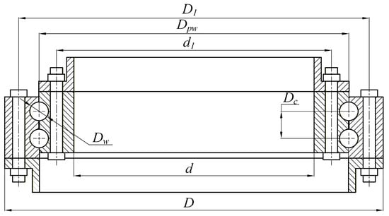
Figure 1.
Basic structure.
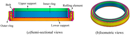
Figure 2.
3D model.

Table 1.
Structural parameters of integrated model bearings and bolts.
Double-row four-point contact ball slewing bearings are composed of upper and lower two rows of rolling elements and inner and outer raceways. To meet the requirements of load-carrying capacity, the number of rolling elements is usually large, and each rolling element is an independent entity. The position angle of each rolling element can be established through a coordinate system to distinguish them. The specific method is as follows: Take the center of the slewing bearing as the origin to establish a three-dimensional coordinate system. Usually, the axial direction is set as the x-axis, and the y-axis or z-axis as the polar axis, as shown in Figure 3:
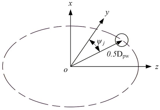
Figure 3.
Bearing coordinate system.
In a row, each rolling element has a corresponding position angle and can be obtained by the formula [30]:
In the formula, j represents the serial number of each rolling element (j = 1, 2, 3, …, Z), where Z represents the number of rolling elements in a single row, and ψj is the angular position of the j rolling element.
The raceway shape of ball bearings mostly adopts a peach-shaped groove structure. Four independent contact points can be established between the rolling elements and the inner and outer raceways, forming two contact pairs [31], as shown in Figure 4:
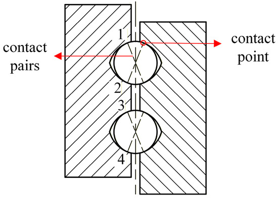
Figure 4.
Contact points and contact pairs.
During the installation of slewing bearings, the outer ring is typically mounted on the frame, while the inner ring is connected to the upper rotating component. Due to the fixed outer ring, under the action of combined loads, the inner ring will produce axial, radial and angular displacements relative to the outer ring. The positional and angular changes in the inner ring cause the inner and outer rings to approach each other and squeeze the rolling elements, generating contact loads. The distance between any rolling element and the center of the raceway radius of curvature before loading is
In the formula, ri and ro represent the curvature radii of the inner and outer raceways, fi and fo are the curvature radius coefficients of the inner and outer raceways, Dw is the diameter of the rolling elements, Ga is the clearance of the bearing (in this study, a zero clearance is adopted), and α0 is the contact angle between the rolling elements and the raceways, as shown in Figure 5:
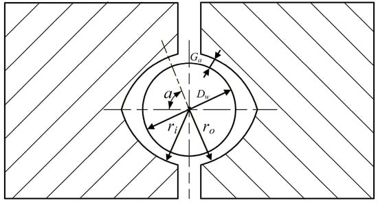
Figure 5.
Contact structure parameters.
After loading, the distance between the curvature centers of the inner and outer raceways will cause rigid body displacement, including radial displacement, axial displacement and angular displacement.
After loading, the equivalent axial distance of the inner ring consists of the following three parts:
The equivalent radial distance of the inner ring consists of the following three parts:
Therefore, the equivalent axial distance and equivalent radial distance of the inner ring after loading are
Since the outer ring is fixed on the frame, the displacement of the raceway curvature center is 0. Therefore, the distance between the inner and outer raceway curvature centers after loading is
Based on the actual situation, the distance between the curvature centers of the inner and outer raceways of the upper row after loading is
In the formula, the upper operation sign applies to contact pair 1, and the lower operation sign applies to contact pair 2.
The distance between the curvature centers of the inner and outer raceways of the lower row is
In the formula, the upper operation sign applies to contact pair 3, and the lower operation sign applies to contact pair 4. δa represents the axial displacement of the inner ring after loading, δr represents the radial displacement of the inner ring after loading, θ represents the angular displacement of the inner ring after loading, and Ri represents the trajectory radius of the inner ring groove curvature center, where
When the inner ring is subjected to a load, it will move relative to the outer ring, and the contact angle between the rolling elements and the raceway will also change. The contact angle of the contact pair n (n = 1, 2, 3, 4) after the load change is
In the formula, the upper signs apply to contact pairs 1 and 3, while the lower signs apply to contact pairs 2 and 4.
The contact deformation between the rolling elements and the inner and outer rings is
The relationship between the normal contact load and contact deformation of the rolling elements at different position angles is
In the formula, Kn is defined as the total load–deformation constant between the ball and the inner and outer raceways.
For bearings made of bearing steel:
In the formula, ∑ρi represents the sum of the principal curvatures of the contact point between the steel ball and the inner raceway, ∑ρe represents the sum of the principal curvatures of the contact point between the steel ball and the outer raceway, nδi represents the coefficient related to the principal curvature function F(ρi) of the contact point between the steel ball and the inner raceway, and nδe represents the coefficient related to the principal curvature function F(ρe) of the contact point between the steel ball and the outer raceway.
The mechanical equilibrium equation in the radial direction of the bearing after it is subjected to load is
The mechanical equilibrium equation in the axial direction is
The mechanical equilibrium equation of the overturning moment is
Equations (12)–(14) are three-element nonlinear equations with δa, δr, and θ as unknowns. For a given external load, the Newton–Raphson iterative method can be used to solve the axial displacement, radial displacement, and angular displacement of the inner ring of the bearing.
For ball bearings, the contact type between the rolling elements and the raceways is elliptical point contact, and the maximum contact pressure at the midpoint of the contact surface is
In the formula, ∑ρ represents the principal curvature and function of the contact point between the steel ball and the raceway, na and nb are coefficients related to the difference function of the principal curvatures of the contact points and Qmax is the maximum normal contact load between the rolling element and the inner and outer raceways.
3. Finite Element Numerical Simulation and Analysis
3.1. Contact Load
3.1.1. Finite Element Meshing and Simplification Processing
Double-row four-point contact ball slewing bearings are relatively large in size and have a large number of rolling elements. When conducting finite element analysis, the use of solid models for the rolling elements needs to take into account the contact between the rolling elements and the raceways. The mesh in this part needs to be more refined, and each rolling element needs to be in contact with the raceways. After the bearing bears a load, the contact between the rolling elements and the raceways is a nonlinear problem. This makes the calculation results very difficult to converge. Here, the rolling elements are replaced by MPC184 rigid rod units and COMBIN39 nonlinear spring units. The unidirectional force characteristics of the nonlinear springs can well express the nonlinear contact behavior of the rolling element raceways. The specific method is as follows: The centers of curvature radii of the inner and outer raceways of the same contact pair are connected using COMBIN39 elements, and then the centers of curvature radii of the raceways are connected to the corresponding raceways using MPC184. Each rolling element is composed of two nonlinear spring elements and eight rigid rods, as shown in Figure 6. The contact stiffness of the nonlinear spring elements can be obtained from Equation (16). Meanwhile, the connection between the bolts and nuts and the support of the bearing also belongs to a nonlinear problem. BEAM188 is a three-dimensional beam element that can simulate various mechanical behaviors such as tension, compression, bending, shearing and torsion. The load on bolts mainly includes axial tensile force and horizontal shear force. Using beam elements instead of bolts can further reduce nonlinearity. At the same time, coupling the two ends of the element with the bolt holes can effectively transmit force and moment. Other structural meshes adopt hexahedral meshes, with the element type set to SOLID185. After the division is completed, the total number of meshes is 418,656.
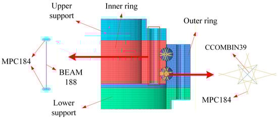
Figure 6.
Simplification of the mesh of the model as well as the bolts and rolling elements.
3.1.2. Boundary Condition Setting
Taking a certain model of 200 t truck crane as an example, the load conditions provided by the enterprise, axial force Fa = 1.3825 × 10⁶ N, radial force Fr = 1.3854 × 10⁵ N, and overturning moment M = 5.3178 × 10⁹ N·mm, are used as the load inputs for theoretical calculation and finite element simulation. In light of the actual situation of the truck crane, the outer ring of the slewing bearing is connected to the base through bolts. Here, a fixed constraint is applied to the lower surface of the lower support. The upper surface of the inner ring is connected to the slewing table (upper support) through bolts. During operation, the load is transmitted to the inner ring of the bearing through the upper support, creating a remote point at the center of the upper surface and coupling with it. Apply the load to the remote point, as shown in Figure 7.
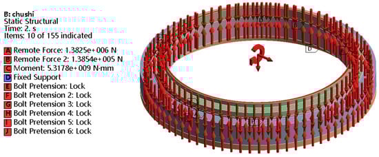
Figure 7.
Load and constraints.
The inner and outer ring materials are 42CrMo, with an elastic modulus of 208 GPa and a Poisson’s ratio of 0.3. The rolling element material is GCr15, with an elastic modulus of 210 GPa and a Poisson’s ratio of 0.29. The bolt material is alloy steel, with an elastic modulus of 206 GPa and a Poisson’s ratio of 0.28. The upper and lower support materials are Q355. Its elastic modulus is 208 GPa and Poisson’s ratio is 0.3.
Both the upper and lower supports are connected to the inner and outer rings of the bearing through bolts. The lower surface of the upper support is set to be in friction contact with the upper surface of the inner ring and the upper surface of the lower support with the lower surface of the outer ring, with a friction coefficient of 0.2. During the contact process between the rolling elements and the raceway, the rolling elements do not rotate, thus restricting the rotational degrees of freedom of the spring. The bolt load is set in two steps. In the first step, the bolt load is set to the allowable preload of 554 kN. In the second load step, the bolt preload is set to lock.
3.1.3. Finite Element Calculation Results of Contact Load
The finite element model was subjected to the constraints and load conditions as shown in Figure 7, and the maximum contact load results were obtained, as shown in Figure 8. The maximum contact load is 106.1 kN, and the maximum contact calculated by Equations (17)–(19) is 105.9 kN, with an error of 0.2%.
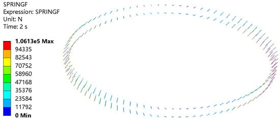
Figure 8.
Finite element results of contact load.
To verify the influence of mesh density on the simulation results, mesh independence tests were conducted. Based on the initial setup, the mesh was coarsened and refined, resulting in a coarse mesh with 356,784 elements and a fine mesh with 469,272 elements, respectively. The results are shown in Figure 9. The maximum contact load obtained by the coarse mesh is 105.6 kN, and that obtained by the fine mesh is 105.1 kN. Compared with the maximum contact load obtained by the original mesh quantity, they have decreased by 0.47% and 0.94% respectively. The results show that the results obtained by the original mesh are accurate.
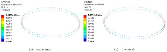
Figure 9.
Verification of mesh accuracy.
3.1.4. Contact Pressure
When nonlinear springs and rigid rods are used instead of rolling elements, the contact pressure and fatigue life between the rolling elements and the raceways cannot be obtained. Each row of the double-row four-point contact ball slewing bearing has 90 rolling elements. After being subjected to load, the maximum contact pressure and the minimum service life will only exist in the contact area between the rolling element that is subjected to the greatest force and the raceway. Only the sub-models of part of the raceway and rolling elements need to be taken for calculation. The sub-model includes one eighth of the inner raceway and half of the rolling elements. The two-dimensional structure is shown in Figure 10a. The three-dimensional structure is shown in Figure 10b.
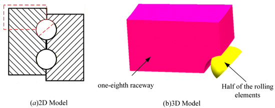
Figure 10.
Sub-model.
When meshing the sub-model, if the entire mesh is refined, a very large number of mesh cells will be generated, making the solution difficult. The contact between the rolling elements and the raceways is only concentrated near the contact area. Only the mesh near the contact point between the rolling elements and the raceways needs to be refined. The contact mesh is refined by adjusting the size of the contact area mesh, and the influence radius is set to 7 mm. The mesh size is 0.45 mm, and the mesh division is shown in Figure 11a.
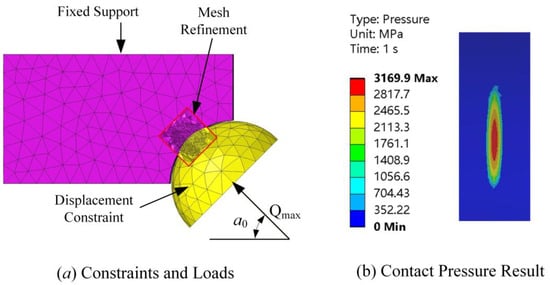
Figure 11.
Boundary conditions and results.
The contact type between the rolling elements and the raceway is frictional contact, with the friction coefficient set at 0.15. A fixed constraint is applied to the raceway surface to restrict the rotational degrees of freedom of the rolling elements, while only the displacement degrees of freedom along the contact normal direction are retained. Apply the maximum contact load obtained in Figure 8 along the normal direction.
In Figure 11b, the finite element calculation results of the contact pressure between the rolling elements and the raceways can be seen. It can be observed from the figure that the maximum contact pressure is 3169.9 MPa, and the contact area is elliptical. The theoretical result of contact pressure calculated by Equation (20) is 3150.4 MPa, and the error between the two is 0.6%. The use of sub-models not only reduces the computing time but also ensures the accuracy of the computing results.
3.2. Fatigue Life
Once the maximum static stresses have been determined, a fatigue assessment is performed by identifying the cyclic stresses associated with the Hertzian contact pressures between the rolling elements and the raceways, arising from their relative motion.
Although the external load rotates together with the inner ring, the load reactions acting on the rolling elements vary over time because the balls move relative to the raceways. While the outer ring, which experiences a rotating load, distributes the load over time along different portions of the raceway and among multiple rolling elements, the inner ring is repeatedly loaded by the passage of the balls in the most highly stressed regions.
Consequently, specific regions of the inner raceway are subjected to repeated contact loading due to the passage of the rolling elements. For this reason, the number of contact stress cycles experienced by these regions is significantly higher than the number of global loading cycles associated with the crane lifting operations and is crucial for fatigue life.
In conclusion, at a given point on the raceway, the contact load varies cyclically from zero to the maximum and back, as illustrated in Figure 12. Since the loading history is equivalent for all rolling elements, and the fatigue life is primarily determined by the limit state under maximum load, the analysis of the fatigue behavior of the raceway at that contact location focused on a single rolling element.
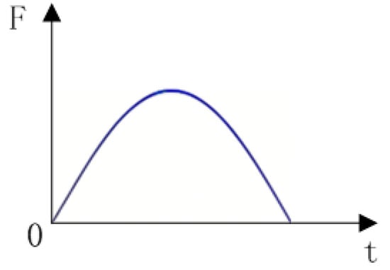
Figure 12.
Load schematic diagram.
3.2.1. Finite Element Analysis of Fatigue Life
ANSYS nCode DesignLife 2022 is a software for structural fatigue durability analysis, widely used in fatigue analysis and life prediction. As part of ANSYS, it has good compatibility with ANSYS Workbench, etc. [32] There are no materials for raceways and rolling elements in the database of ANSYS nCode DesignLife. However, the software provides a drawing module for material fatigue curves. Users only need to input the tensile strength of the material to obtain the fatigue life curve of the material. The tensile strengths of the raceways and rolling elements are 1347 MPa and 1617 MPa respectively. The fatigue curve parameters obtained by the software were corrected [33], and the obtained fatigue curves are shown in Figure 13.
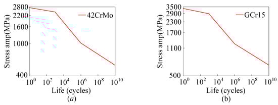
Figure 13.
Material fatigue life curves of (a) raceways and (b) rolling elements.
Fatigue spalling of rolling bearings is mainly caused by the gradual expansion of cracks to the surface due to shear stress beneath the rolling surface [30]. Therefore, when conducting stress analysis, shear stress is selected as the stress standard, and Goodman is used to correct the curve. The calculation results are shown in Figure 14. The minimum life is 8.385 × 10⁴ cycles, and the region with the minimum fatigue life is concentrated at the rolling element–raceway contact interfaces.
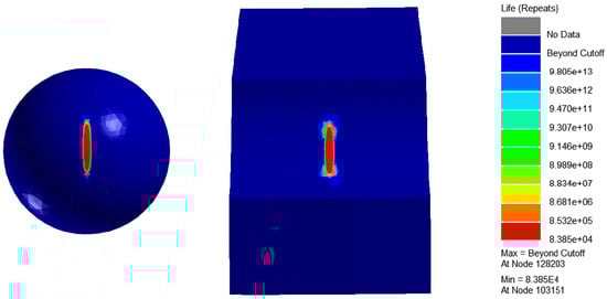
Figure 14.
Contact fatigue life of rolling elements and raceways.
3.2.2. Theoretical Analysis of Fatigue Life
For a four-point contact ball slewing bearing, each rolling element has four distinct contact points with the raceways. It can be assumed that the rolling element is in contact with four raceways. The life of the entire bearing can be obtained by calculating the life of each raceway and combining the results.
The rated dynamic load of the raceway is [30]:
In the formula, i represents the inner circle, and the symbol above should be used for calculation. e represents the outer circle, and the symbol below should be used for calculation. λ and η are correction coefficients, the expression of γ is
When the outer ring of the slewing bearing is fixed on the frame and the inner ring rotates, the equivalent rolling element load on the inner raceway of the bearing is
In the formula, Qkj represents the normal contact load, and k is the number of the raceway. The upper raceway of the upper row is 1, the lower raceway of the upper row is 2, the upper raceway of the lower row is 3, and the lower raceway of the lower row is 4.
The equivalent rolling element load on the outer raceway of the bearing is
By fitting the rated life of each raceway, the rated life of the entire bearing can be obtained. The rated service life of the inner and outer raceways of the double-row four-point contact ball slewing bearing is
The rated service life of the four contact pairs in the upper and lower rows of the bearing is
Then the rated life of the bearing as a whole can be expressed as
The above calculation process is for the life calculation of L-P bearings. Considering the influences of bearing materials, lubrication conditions and usage conditions, etc., the fatigue life needs to be corrected:
In the formula, a1 represents the reliability coefficient, a2 represents the material coefficient, and a3 represents the lubrication state coefficient.
At this point, the result obtained is the total number of rotations of the bearing. By multiplying by the number of rolling elements in a single row, the number of alternating loads experienced by the raceway for each rotation of the bearing can be obtained [34]:
The fatigue life of the bearing calculated by Equation (30) is 8.98 × 10⁴ cycle, and the error between the finite element calculation result and the theoretical calculation result is 6.7%.
By comparing the calculation results of the theoretical model and the finite element model, it is found that they have good consistency under the same load working conditions, which verifies the accuracy of the finite element model. Compared with theoretical models, the finite element model can capture the complex characteristics of the structure more comprehensively and accurately. Therefore, the subsequent influence of structural parameters on bearing performance will use the finite element model and its results.
4. The Influence of Bearing Structural Parameters on the Mechanical Properties of Bearings
4.1. Influence of Contact Angle
When analyzing the influence of contact angle on the mechanical properties of bearings, keeping other parameters and boundary conditions unchanged, the contact angle was uniformly taken from 25° to 65°. The calculation results are shown in Figure 15:
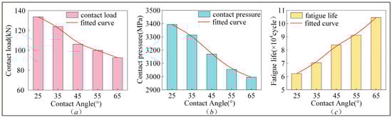
Figure 15.
Influence of contact angle on bearing performance on (a) contact load, (b) contact pressure and (c) fatigue life.
As shown in the figure, the contact load and contact pressure gradually decrease with the increase in the contact angle, approximately showing a linear negative correlation, while the fatigue life gradually increases with the increase in the contact angle, approximately showing a linear positive correlation. When the contact angle increased from 25° to 65°, the contact load decreased by 30.7% (41 kN), the contact pressure decreased by 11.7% (397.6 MPa), and the fatigue life increased by 68% (4.23 × 10⁴ cycle).
The main reason for this phenomenon is that when the external load remains constant and the ratio of the radial load to the axial load is small, increasing the contact angle can reduce the component of the axial force in the normal direction of the contact between the rolling elements and the raceway, lower the contact load and contact pressure between the rolling elements and the raceway, and thereby increase the fatigue life. It is worth noting that when the contact angle is too large, the contact ellipse between the rolling elements and the raceway will be truncated [35], resulting in excessive contact pressure and reduced fatigue life. When designing the mating antennae, edge contact should be avoided.
4.2. Influence of Rolling Element Diameter
When analyzing the influence of rolling element diameter on the mechanical properties of bearings, keeping other parameters and boundary conditions unchanged, the rolling element diameter was uniformly taken from 40 mm to 56 mm. The calculation results are shown in Figure 16:
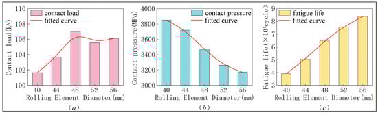
Figure 16.
Influence of rolling element diameter on bearing performance on (a) contact load, (b) contact pressure and (c) fatigue life.
As shown in the figure, the contact load and fatigue life gradually increase with the increase in the diameter of the rolling elements. Among them, the increase rate of the contact load is relatively fast before the diameter of the rolling elements is 48 mm. After the diameter of the rolling elements is 48 mm, although there are fluctuations, the overall trend tends to be stable. Fatigue life approximately shows a linear positive correlation, while contact pressure decreases as the diameter of the rolling elements increases, approximately showing a linear negative correlation. When the diameter of the rolling elements increased from 40 mm to 56 mm, the contact load increased by 4.4% (4 kN), the contact pressure decreased by 17.7% (681.3 MPa), and the fatigue life increased by 115% (4.48 × 10⁴ cycle).
The main reason for this phenomenon is that the external load and contact state have not changed, and the contact load changes little. However, as the diameter of the rolling elements increases, the contact area between the rolling elements and the raceway increases. The increase in the contact area will reduce the contact pressure, thereby increasing the fatigue life. When the diameter of the rolling elements increases, the size of the bearing usually also increases, and the space limitations of the installation position need to be taken into consideration. In addition, when the number of rolling elements remains unchanged, an increase in the diameter of the rolling elements will reduce the distance between the rolling elements and the thickness of the isolation blocks. To ensure the safety and reliability of the bearing operation, the thickness of the isolation blocks should not be too small.
4.3. Influence of Number of Rolling Elements
When analyzing the influence of the number of rolling elements on the mechanical properties of bearings, keeping other parameters and boundary conditions unchanged, the number of rolling elements was uniformly taken from 50 to 90. The calculation results are shown in Figure 17:
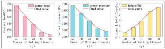
Figure 17.
Influence of the number of rolling elements on bearing performance on (a) contact load, (b) contact pressure and (c) fatigue life.
As shown in the figure, the contact load and contact pressure gradually decrease with the increase in the number of rolling elements, and the decrease rate is relatively fast before the number of rolling elements reaches 80, and tends to be flat after the number of rolling elements reaches 80. The fatigue life gradually increases with the increase in the number of rolling elements. It approximately shows a linear positive correlation. When the number of rolling elements increased from 50 to 90, the contact load decreased by 46.0% (90 kN), the contact pressure decreased by 20.1% (796.6 MPa), and the fatigue life increased by 125% (4.65 × 10⁴ cycle).
The main reason for this phenomenon is that when the number of rolling elements increases, the number of rolling elements bearing the load also increases, and the load allocated to each individual rolling element decreases, resulting in a reduction in contact load and contact pressure, thereby enhancing fatigue life. Similarly, when the diameter of the rolling elements remains unchanged, increasing the number of rolling elements will also reduce the spacing between the rolling elements and the thickness of the isolation blocks.
4.4. Influence of Raceway Curvature Radius Coefficient
For the convenience of processing, the curvature radius coefficients of the inner and outer raceways of slewing bearings usually adopt the same value. When analyzing the influence of the curvature radius coefficient of the raceways on the mechanical properties of the bearings, keeping other parameters and boundary conditions unchanged, the curvature radius coefficients of the inner and outer raceways are uniformly taken from 0.505 to 0.545 simultaneously. The calculation results are shown in Figure 18:
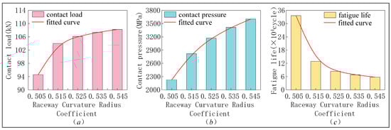
Figure 18.
Influence of raceway curvature radius coefficient on bearing performance on (a) contact load, (b) contact pressure and (c) fatigue life.
As shown in the figure, the contact load and contact pressure gradually increase with the increase in the raceway curvature radius coefficient, and the increasing rates both show a decreasing trend. This phenomenon of contact load is more obvious, and the fatigue life gradually decreases with the increase in the raceway curvature radius coefficient. The reduction degree is relatively large before the raceway curvature radius coefficient is 0.515. When the raceway curvature radius coefficient increased from 0.505 to 0.515, the contact load increased by 14.4% (14 kN), the contact pressure increased by 61.7% (1374.8 MPa), and the fatigue life decreased by 83% (27.9 × 10⁴ cycle).
The main reason for this phenomenon is that, as the radius of curvature coefficient of the raceway increases, the fit between the rolling elements and the raceway decreases and the contact area reduces, which leads to an increase in contact load and contact pressure and a decrease in fatigue life. Reducing the raceway curvature radius coefficient is beneficial for enhancing the load-bearing capacity, but it will increase the frictional torque between the rolling elements and the raceway.
4.5. Sensitivity Analysis of Bearing Structural Parameters on Mechanical Performance
In the previous content, the influence of four bearing structural parameters on their mechanical properties has been analyzed. Each influencing factor has five values. By numbering the five values of each influencing factor from 1 to 5, a single horizontal coordinate can be used to replace the original four horizontal coordinates. The sensitivity curve of the bearing structure parameters to its contact load, contact pressure and fatigue life is shown in Figure 19. As can be seen from Figure 19a, the sensitivity of the bearing structure parameters to its contact load, from largest to smallest, is the number of rolling elements, contact angle, raceway curvature radius coefficient and rolling element diameter. As can be seen from Figure 19b, the sensitivity of the bearing structure parameters to its contact pressure, from largest to smallest, is the raceway curvature radius coefficient, the number of rolling elements, the diameter of the rolling elements, and the contact angle. As can be seen from Figure 19c, the sensitivity of bearing structural parameters to its fatigue life, from largest to smallest, is the raceway curvature radius coefficient, the number of rolling elements, the diameter of the rolling elements, and the contact angle.
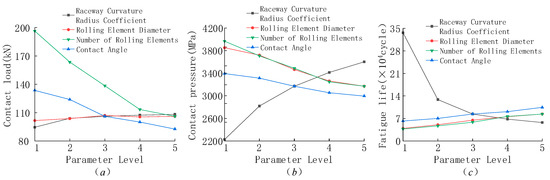
Figure 19.
Sensitivity curves of the influence of bearing structural parameters on its mechanical properties on (a) contact load, (b) contact pressure and (c) fatigue life.
5. Influence of Bolt Parameters on the Mechanical Properties of Bearings
During the process of the bearing loads, the main function of the outer bolt is to fix the outer ring of the bearing to the lower support, and it does not have a significant impact on the transmission of the load. Therefore, it is only necessary to analyze the inner ring bolt.
5.1. Influence of Number of Bolts
When analyzing the influence of the number of bolts on the mechanical properties of bearings, keeping other parameters and boundary conditions unchanged, the number of inner ring bolts was uniformly taken from 24 to 72. The calculation results are shown in Figure 20:
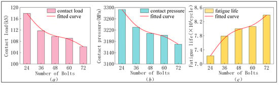
Figure 20.
Influence of the number of bolts on bearing performance on (a) contact load, (b) contact pressure and (c) on fatigue life.
As shown in the figure, the contact load and contact pressure decrease with the increase in the number of bolts, and the rate of decrease is relatively fast before the number of bolts reaches 36. The fatigue life also increases with the increase in the number of bolts, and the rate of increase is relatively fast before the number of bolts reaches 36. When the number of bolts increased from 24 to 72, the contact load decreased by 10.0% (12 kN), the contact pressure decreased by 3.7% (122.8 MPa), and the fatigue life increased by 16% (1.15 × 10⁴ cycle).
The main reason for this phenomenon is that when the preload of a single bolt remains unchanged, increasing the number of bolts will increase the overall preload of the bolts, resulting in greater deformation of the inner and outer rings and a more uniform load distribution. Reduce the maximum load and contact pressure, and increase the fatigue life.
5.2. Influence of Bolt Preload
When analyzing the influence of bolt preload on the mechanical properties of bearings, keeping other parameters and boundary conditions unchanged, the preload of the inner ring bolts was uniformly taken from 222 kN to 554 kN. The calculation results are shown in Figure 21:
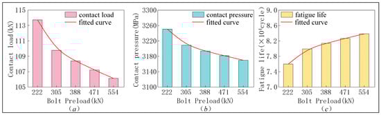
Figure 21.
Influence of bolt preload on bearing performance on (a) contact load, (b) contact pressure and (c) fatigue life.
As shown in the figure, the contact load and contact pressure decrease with the increase in the bolt preload. The fatigue life gradually increases with the increase in the bolt preload. When the bolt preload increased from 222 kN to 554 kN, the contact load decreased by 6.7% (8 kN), the contact pressure decreased by 2.5% (80.7 MPa), and the fatigue life increased by 10% (0.80 × 10⁴ cycle).
The main reason for this phenomenon is that during the process of tightening the bolts, a squeezing effect is exerted on the inner and outer rings, causing the raceway to deform. The deformation is transmitted to the nonlinear spring through the rigid rod, resulting in the deformation of the nonlinear spring unit. The load is transmitted to the inner ring of the bearing through bolts. Under the action of external loads, the preload of the bolts will offset part of the external loads, reducing the load transmitted to the bearing, the maximum load and contact pressure, and increasing the fatigue life.
5.3. Influence of Shim Thickness
When analyzing the influence of gasket thickness on the mechanical properties of bearings, keeping other parameters and boundary conditions unchanged, the thickness of the inner ring gasket was uniformly taken from 0 mm to 40 mm. The calculation results are shown in Figure 22:
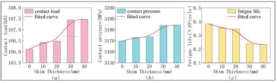
Figure 22.
Influence of gasket thickness on bearing performance on (a) contact load, (b) contact pressure and (c) fatigue life.
As shown in the figure, the contact load and contact pressure increase with the increase in gasket thickness, while the fatigue life decreases with the increase in gasket thickness. The variation ranges are all relatively small. When the gasket thickness increased from 0 mm to 40 mm, the contact load increased by 1.3% (1.4 kN), the contact pressure increased by 0.5% (14.4 MPa), and the fatigue life decreased by 1.8% (0.15 × 10⁴ cycle).
The main reason for this phenomenon is the presence of gaskets, which prevent the bolt preload from being fully applied to the inner and outer rings of the bearing. The gaskets disperse the preload, resulting in an increase in the contact load of the bolts. In the connection of bearings, the main function of gaskets is to disperse the pressure generated by bolts, making the force on the surface of the supporting structure more uniform and thereby enhancing the stability of the connection.
5.4. Sensitivity Analysis of Bolt Parameters on Bearing Mechanical Properties
Here, the same method is adopted to number the five values of each influencing factor of the three bolt parameters from 1 to 5, and the sensitivity curves of the bolt parameters to the bearing contact load, contact pressure and fatigue life are obtained, as shown in Figure 23. As can be seen from Figure 23a, the sensitivity of bolt parameters to the contact load of the bearing, from largest to smallest, is the number of bolts, the bolt preload, and the thickness of the gasket. As can be seen from Figure 23b, the sensitivity of bolt parameters to the contact pressure of the bearing, from largest to smallest, is the number of bolts, the bolt preload, and the thickness of the gasket. As can be seen from Figure 23c, the sensitivity of bolt parameters to the fatigue life of bearings, from largest to smallest, is the number of bolts, bolt preload, and gasket thickness.
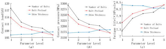
Figure 23.
Sensitivity curves of bolt parameters on the mechanical properties of bearings on (a) contact load, (b) contact pressure and (c) fatigue life.
6. Conclusions
Before analyzing the influence of structural parameters on the performance of double-row four-point contact ball slewing bearings in this paper, the finite element analysis was conducted. First, the finite element simulation results were compared with the theoretical results, with an error of 0.2%. At the same time, the influence of the mesh size used on the accuracy of the simulation results was verified. Through the research, the following conclusions were obtained:
- Among all the parameters, the order of influence on the contact load is as follows: the number of rolling elements, contact angle, raceway curvature radius coefficient, the number of bolts, bolt preload, rolling element diameter and gasket thickness. The influence of the number of rolling elements on the contact load is 90 kN (46%).
- Among all the parameters, the order of influence on contact pressure is as follows: raceway curvature radius coefficient, number of rolling elements, rolling element diameter, contact angle, number of bolts, bolt preload and gasket thickness. The influence of the raceway curvature radius coefficient on the contact pressure is 1374.8 MPa (61.7%).
- Among all the parameters, the order of influence on fatigue life is as follows: raceway curvature radius coefficient, number of rolling elements, diameter of rolling elements, contact angle, number of bolts, bolt preload and gasket thickness. The influence of the radius of curvature coefficient on the fatigue life is 27.9 × 10⁴ cycles (83%).
In the process of designing and selecting slewing bearings, when the minimum contact load is required, the influence of the number of rolling elements should be considered first. When the minimum contact pressure and maximum service life are required, the raceway curvature radius coefficient should be considered first. At the same time, not only should the influence of the structural parameters of the bearing itself on its mechanical properties be paid attention to, but the influence of the bolt parameters should also be taken into consideration. This is especially the case when the maximum service life is the design goal, as the number of bolts and the preload force can even affect the fatigue life of the bearing by more than 10%.
Author Contributions
Conceptualization, Y.W. and H.Y.; methodology, Y.W.; software, H.Y.; validation, Y.W., H.Y. and T.W.; formal analysis, Y.W.; investigation, Y.W.; resources, Y.W.; data curation, Y.W.; writing—original draft preparation, H.Y.; writing—review and editing, Y.W. and Y.L.; visualization, Y.W.; supervision, F.L.; project administration, Y.W.; funding acquisition, Y.W. All authors have read and agreed to the published version of the manuscript.
Funding
This research was funded by the Major Science and Technology Projects in Henan Province, grant number 251100220200.
Data Availability Statement
The original contributions presented in this study are included in the article material. Further inquiries can be directed to the corresponding author.
Conflicts of Interest
The authors declare no conflicts of interest.
References
- He, Z.; Shi, Z.; Qin, D.; Wen, J.; Shao, J.; Liu, X.; Xie, X. Study on Comprehensive Performance of Four-Point Contact Ball Slewing Bearings Based on a Bearing Support Bolt-Integrated Model. Machines 2024, 12, 814. [Google Scholar] [CrossRef]
- Wang, M. Analysis of Dynamics, Temperature and Fatigue Characteristics of Axlebox Bearings Based on Force-Thermal Coupling. Ph.D. Thesis, Shijiazhuang Tiedao University, Shijiazhuang, China, 2025. [Google Scholar]
- Wang, H.; Chen, Y. Calculation Method of Carrying Capacity and Rated Life of Slewing Bearings. Bearing 2008, 7–9, 17. [Google Scholar]
- Wang, H.; Chen, Y. Calculation of Carrying Capacity of Ball-Cylindrical Roller Combined Slewing Bearings. Bearing 2010, 10–12. [Google Scholar] [CrossRef]
- Wang, H.; Li, Y.; Tian, R. Calculation of Carrying Capacity of Multi-row Roller Slewing Bearings. Bearing 2012, 8–11. [Google Scholar] [CrossRef]
- Qiao, S.G.; Xu, M.Q.; Wen, J.B.; Wang, J.E. Calculation of Static Carrying Capacity of Ball-Cylindrical Roller Combined Slewing Bearings. J. Mech. Transm. 2011, 35, 27–29. [Google Scholar]
- Li, Y.F. Effects of Design Parameters of Wind Power Slewing Bearing on Carrying Capacity. Bearing 2011, 7–11. [Google Scholar] [CrossRef]
- Śpiewak, S. Methodology for calculating the complete static carrying capacity of twin slewing bearing. Mech. Mach. Theory 2016, 101, 181–194. [Google Scholar] [CrossRef]
- Phadatare, H.P.; Pratiher, B. Nonlinear modeling, dynamics, and chaos in a large deflection model of a rotor–disk–bearing system under geometric eccentricity and mass unbalance. Acta. Mech. 2020, 231, 907–928. [Google Scholar] [CrossRef]
- Niu, R.J.; Xu, J.C.; Shao, X.H.; Deng, S.E. Influence of Asymmetric Contact Angle on Static and Dynamic Carrying Capacity of Four-point Contact Ball Slewing Bearing. Bearing 2017, 4–8. [Google Scholar] [CrossRef]
- Zou, Y.; Sun, W.; Wang, H.; Xu, T.; Wang, B. Research on the Calculation Method for the Contact Stress of Wind Turbine Main Shaft Bearings Based on Finite Element Analysis. Lubricants 2025, 13, 226. [Google Scholar] [CrossRef]
- He, P.; Qian, Q.; Wang, Y.; Liu, H.; Guo, E.; Hang, H. Influence of finite element mesh size on the carrying capacity analysis of single-row ball slewing bearing. Adv. Mech. Eng. 2021, 13, 4. [Google Scholar] [CrossRef]
- Zheng, J.; Guo, Y.; Ji, J.; Tong, V.-C.; Zhang, X.; Dong, H.; Hu, S.; Xu, L. Contact force and pressure analysis of the three-row roller pitch bearing in a large-scale wind turbine. Proc. Inst. Mech. Eng. C J. Mech. Eng. Sci. 2024, 238, 9475–9490. [Google Scholar] [CrossRef]
- Graßmann, M.; Schleich, F.; Stammler, M. Validation of a finite-element model of a wind turbine blade bearing. Finite Elem. Anal. Des. 2023, 221, 103957. [Google Scholar] [CrossRef]
- Martín, I.; Heras, I.; Aguirrebeitia, J.; Macareno, L.M. Influence of the geometrical design on ball and crossed roller wire race bearing behavior under axial load. Tribol. Int. 2021, 156, 106817. [Google Scholar] [CrossRef]
- MartIn, I.; Aguirrebeitia, J.; Heras, I.; Abasolo, M. Efficient Finite Element modelling of crossed roller wire race slewing bearings. Tribol. Int. 2021, 161, 107098. [Google Scholar] [CrossRef]
- He, P.; Wang, Y.; Liu, H.; Guo, E.; Wang, H. Influence of the elastic and elastic-plastic material parameters on the mechanical properties of slewing bearings. Adv. Mech. Eng. 2021, 13, 1. [Google Scholar] [CrossRef]
- Kim, S.-W.; Song, J.-W.; Hong, J.-P.; Kim, H.-J.; Kang, J.-H. Finite Element Analysis and Validation of Wind Turbine Bearings. Energies 2024, 17, 692. [Google Scholar] [CrossRef]
- Mohamed Anwar, A.U.; Babu, S.; Starvin, M.S. Experimental validation and contact behaviour analysis of slewing ring thrust ball bearings with FEA simulation. Sādhanā 2024, 49, 267. [Google Scholar] [CrossRef]
- Porziani, S.; Biancolini, M.E.; Brutti, C. Analysis of wind turbine pitch 4-point contact bearing. IOP Conf. Ser. Mater. Sci. Eng. 2023, 1275, 012034. [Google Scholar] [CrossRef]
- Huang, L.Y.; Wang, H.; Ji, X. Calculation of Load Distribution of Three-row Roller Slewing Bearing Considering Fastening Bolts. Chin. J. Eng. Des. 2021, 28, 350–357+366. [Google Scholar]
- Qiu, B.A. Mechanical Analysis and Life Calculation of Double-row Different Diameter Ball Slewing Bearing Based on Load Distribution Factor. Bearing 2023, 16–21. [Google Scholar] [CrossRef]
- Balyakin, V.B.; Zhilnikov, E.P.; Pilla, K.K. Method for calculating the fatigue life of bearings taking into account wearing of rolling elements. J. Frict. Wear 2020, 41, 359–364. [Google Scholar] [CrossRef]
- Cheng, H.; Zhang, Y. Effect of spatial position of the ball and random parameters on rolling bearing fatigue life. J. Braz. Soc. Mech. Sci. Eng. 2022, 44, 246. [Google Scholar] [CrossRef]
- Zheng, H.T.; Li, Q.L.; Ji, Y.; Zhu, C.F. Analysis of Mechanical and Fatigue Performance of Yaw Bearings for Large Megawatt Wind Turbines. Bearing 2025, 8–17. [Google Scholar] [CrossRef]
- Cui, Y.B.; Liang, Y.S.; Guo, X.D.; Xie, K.; Guo, Y.P. Analysis of Load and Fatigue Life of Pitch Bearing for Wind Turbine. Technol. Innov. Appl. 2025, 15, 91–94. [Google Scholar]
- Balyakin, V.B.; Zhilnikov, E.P.; Kosenok, B.B.; Lavrin, A.V. Study of the influence of ring misalignment in rolling bearings on frictional torque and the fatigue life of supports. J. Frict. Wear 2017, 38, 7–12. [Google Scholar] [CrossRef]
- Fang, B.; Zhang, J. Analytical Determination of the Optimal Clearance for the Fatigue Life of Ball Bearing Under Different Load Conditions. J. Tribol. 2022, 144, 10. [Google Scholar] [CrossRef]
- Lu, X.Y.; Wang, D.D.; Li, D.G.; Liu, H. Research on Contact Surface Stress Analysis of Solid Lubricated Roller Bearings. Tool Eng. 2022, 56, 88–91. [Google Scholar]
- Deng, S.E.; Xue, J.X.; Niu, R.J.; Yang, H.S. Design Principles of Rolling Bearings; China Quality and Standards Press: Beijing, China, 2024; pp. 323–328+340. [Google Scholar]
- Li, J.F.; Wen, B.; Tian, P.; Ma, S.J.; Yan, K. Contact State Analysis of Four-Point Contact Ball Bearing for Typical Working Conditions. Bearing 2023, 26–31. [Google Scholar] [CrossRef]
- Fu, S.S. ANSYS nCode DesignLife Fatigue Analysis Basic and Case Tutorial; People’s Posts and Telecommunications Press: Beijing, China, 2020; pp. 47–54, 159–165. [Google Scholar]
- Ouyang, W.J. Finite Element Simulation and Parametric Analysis of Pitch Bearing Connection Performance of Wind Turbine. Master’s Thesis, Qinghai University, Xining, China, 2024. [Google Scholar]
- He, P.; Hong, R.; Wang, H.; Lu, C. Fatigue Life Analysis of Slewing Bearings in Wind Turbines. Int. J. Fatigue 2018, 111, 233–242. [Google Scholar] [CrossRef]
- Stammler, M.; Menck, O.; Guo, Y.; Keller, J.A. Wind Turbine Design Guideline DG03: Yaw and Pitch Bearings; National Renewable Energy Laboratory (NREL): Golden, CO, USA, 2024. [Google Scholar]


Disclaimer/Publisher’s Note: The statements, opinions and data contained in all publications are solely those of the individual author(s) and contributor(s) and not of MDPI and/or the editor(s). MDPI and/or the editor(s) disclaim responsibility for any injury to people or property resulting from any ideas, methods, instructions or products referred to in the content. |
© 2026 by the authors. Licensee MDPI, Basel, Switzerland. This article is an open access article distributed under the terms and conditions of the Creative Commons Attribution (CC BY) license.