Article

Generalized Design Methodology for Dual-Arm Robotic Platforms: From Conceptualization to Experimental Validation Within the MANiBOT Framework

by
Mario Peñacoba-Yagüe
* and
Jesús Enrique Sierra-García
*
Department of Digitalization, University of Burgos, 09001 Burgos, Spain
*
Authors to whom correspondence should be addressed.
Machines 2026, 14(1), 74; https://doi.org/10.3390/machines14010074
Submission received: 19 November 2025 / Revised: 31 December 2025 / Accepted: 2 January 2026 / Published: 7 January 2026

Abstract

This work proposes a general methodology for the design and experimental validation of dual-arm robotic platforms intended for intelligent manipulation tasks in real-world environments. The proposed framework formalizes the complete engineering process, from the definition of functional requirements to the structural validation of the final prototype, ensuring reproducibility and adaptability across different applications. The methodology is organized into five main stages: (i) requirement analysis and context characterization; (ii) conceptual architecture definition; (iii) detailed mechanical design and structural analysis; (iv) prototype construction and integration; and (v) experimental validation and iterative refinement. Each stage defines its expected deliverables, evaluation metrics, and decision criteria to support systematic design progression. The approach is demonstrated through its implementation within the European project MANiBOT, where the framework guided the development of a modular bimanual robotic platform capable of integrating collaborative manipulators and conveyor subsystems for dual-arm manipulation. Structural testing, deflection measurements, and stability analyses confirmed the robustness and safety of the resulting design. Beyond this specific case, the proposed methodology provides a replicable and extensible design reference for research and industrial teams developing modular robotic structures, supporting the standardization of engineering practices in bimanual mobile robotics.

1. Introduction

Although robotic perception, cognition, and control have progressed considerably in recent years, current collaborative robots remain constrained in terms of physical capabilities, especially when benchmarked against human manipulation skills. These limitations are especially evident in tasks that demand safe, efficient, and robust manipulation of objects in real-world, human-shared environments. Industrial robots, on the other hand, deliver speed and precision primarily in controlled, predefined settings where object properties and task conditions are fully modeled, and human presence is minimized. Such constraints hinder the deployment of collaborative robotic systems in sectors such as retail logistics, warehousing, and airport operations, where environments are dynamic, objects are heterogeneous, and task requirements are not always predefined in advance [1].
Humans, by contrast, manage complexity through an exceptional combination of perceptual awareness, adaptive reasoning, and coordinated motor actions, enabling fluid responses to uncertain or changing environments [2]. Everyday manipulation tasks rely not only on dexterous bimanual coordination, but also on the use of non-prehensile strategies—such as pushing, sliding, or rotating—and the seamless integration of multimodal sensory feedback [3,4]. These capabilities allow humans to adapt in real time to unexpected changes, deformable or occluded objects, and spatial constraints. Replicating such levels of adaptability and robustness in service robotics remains one of the most pressing challenges in the field [5,6].
In this context, research has increasingly explored the integration of dual-arm configurations on mobile robotic bases to approximate human-like versatility. However, the mechanical embodiment of such systems remains underexplored [7]. Most studies emphasize perception, control, or learning aspects, while the design methodology of the physical platform itself—which governs stiffness, reach, balance, and modularity—has rarely been formalized. As a result, many prototypes are developed in isolation, lacking common reference metrics, reproducibility, or design traceability [8]. Establishing standardized design workflows would allow future researchers to evaluate, replicate, and benchmark new robotic architectures with greater scientific consistency.
To address this gap, there is a growing need for methodologies that standardize the design of robotic platforms capable of bimanual manipulation. While numerous research efforts have focused on improving perception and control, comparatively less attention has been devoted to the systematic mechanical design process that underpins the stability, reachability, and safety of dual-arm robotic structures [9]. The absence of shared guidelines often leads to ad hoc designs that are difficult to reproduce or adapt across different domains.
In response to safety and reliability concerns, the design of collaborative robotic systems is governed by international standards such as [10,11,12], which define essential safety requirements, interaction modes, and force or pressure limits for human–robot collaboration. These standards play a fundamental role in ensuring safe operation and regulatory compliance. However, they are intentionally technology-agnostic and prescriptive in nature: they specify what must be fulfilled, but do not address how complex robotic platforms—such as mobile dual-arm systems—should be systematically designed, dimensioned, and integrated from a mechanical and system-level perspective.
In particular, existing standards do not provide guidance on (i) structured design workflows for mobile bimanual platforms, (ii) the integrated mechanical embodiment of dual manipulators mounted on autonomous mobile robots, (iii) the adaptation of the platform architecture to specific operational use cases, (iv) modular and detachable designs enabling the reuse of heterogeneous robotic arms and mobile bases, or (v) practical validation strategies illustrated through complete, real-world systems.
This work contributes to filling that gap by proposing a structured, reproducible, and domain-independent methodology for the design and validation of dual-arm robotic platforms. The methodology formalizes each step of the mechanical development process—from requirement identification to structural validation—specifying the deliverables, evaluation metrics, and decision criteria that ensure compliance with functional and safety constraints. This provides a scientific foundation for engineering future dual-arm systems with predictable performance and documented design rationale.
The approach is demonstrated through its application to the design of the MANiBOT platform [13], a dual-arm robotic structure tailored for real-world retail and airport environments.
The structure of the paper is as follows: Section 2 reviews related work and the technological background. Section 3 defines the robotic platform design methodology. Section 4 describes the platform operational scenarios. Section 5 details how the design methodology is applied to the mechanical requirements derived from these scenarios. Section 6 describes the tests performed on the robotic platform. Section 7 presents the experimental results, while Section 8 concludes with reflections and future research directions.

2. State-of-the-Art

The development of mobile dual-arm robotic platforms represents a rapidly evolving frontier in robotics engineering, combining advances in mechanical design, system integration, and validation methodologies. Multi-arm systems extend manipulation capabilities beyond single-arm baselines by enabling cooperative lifting, coordinated handovers, stabilization of large or deformable objects, and non-prehensile strategies [14]. Recent studies have reported significant gains in efficiency and adaptability when coordinated planning is combined with dual-arm execution [15,16]. However, these advantages introduce new challenges related to kinematic redundancy, inter-arm synchronization, collision avoidance, and structural rigidity—all of which are strongly influenced by the mechanical architecture that supports the manipulators.
Early developments focused on fixed dual-arm cells designed for assembly or laboratory automation, demonstrating the feasibility of high-precision bimanual manipulation under controlled conditions [17,18]. Subsequent research extended these systems toward mobile or semi-mobile embodiments capable of performing navigation, inspection, and telemanipulation tasks [19,20]. Collectively, these works underline a persistent design trade-off: the supporting frame must be compact and AMR-compatible, yet sufficiently stiff and well-balanced to withstand the forces and dynamic interactions generated by dual manipulators operating in confined or human-shared environments [21,22].
To explore this balance between stability and adaptability, many research groups have developed prototype platforms based on lightweight aluminum profiles, which accelerate early iterations and reduce fabrication costs [23]. While suitable for validating motion coordination and control concepts, such prototypes often lack the rigidity and endurance required for real industrial deployment. Consequently, more advanced designs have incorporated steel-reinforced or hybrid frames, improving stiffness, vibration resistance, and fatigue performance [24]. In parallel, several studies have integrated conveyors, linear axes, and height-adjustable mechanisms to extend workspace coverage and enable multi-height object transfer. These additions increase task versatility but also complicate mass distribution, modularity, and mechanical integration, leading most reported systems to remain task-specific prototypes rather than reusable, documented design frameworks.
In parallel to research-driven developments, the design of industrial and collaborative robotic systems has been strongly influenced by international safety standards such as [10,11,12], which define mandatory requirements for safe operation, human–robot interaction, and system integration. These standards constitute an essential reference framework and are widely adopted in both industrial practice and applied research. However, by design, they focus on compliance and risk mitigation rather than on mechanical engineering methodology. As such, they do not provide guidance on the systematic mechanical design of mobile dual-arm platforms, nor on architectural decisions related to arm placement, structural dimensioning, modularity, or the integration of task-specific subsystems such as conveyors or lifting mechanisms. Consequently, while standards ensure safety boundaries, they leave open the question of how complex dual-arm robotic platforms should be designed, documented, and validated as reproducible engineering artifacts.
Across the literature, existing works consistently show that the success of dual-arm systems depends as much on methodical mechanical design as on control and sensing [25]. Yet despite numerous case studies, there is still no unified, reproducible methodology that guides the design, construction, and validation of dual-arm robotic platforms as engineering artifacts. In particular, the community lacks a framework capable of: (i) structuring requirements into functional and operational categories; (ii) translating them into architectural decisions such as arm placement, conveyor geometry, and maintainability features; (iii) defining standardized analysis and test artifacts (e.g., CAD/FEA models, stability and reachability envelopes, vibration and multi-height tests); and (iv) establishing quantitative acceptance criteria and traceability from requirement to experimental evidence.
To make this gap explicit, Table 1 provides a concise version of the comparative analysis of representative dual-arm robotic platforms reported in the literature, focusing on whether and how design methodologies are formalized, their degree of generality, and their treatment of mobility, adaptability, and validation. This comparison highlights that most existing works prioritize task- or application-specific solutions, while lacking a unified and reproducible mechanical design framework. The complete and detailed comparison is provided in Appendix A.1 (Table A1).
In response to this gap, the present work proposes a structured and reproducible design methodology for mobile dual-arm robotic platforms—spanning from requirement identification through conceptual and detailed mechanical design, prototype construction, and experimental validation.

3. Generalized Design Framework for Dual-Arm Robotic Platforms

This section introduces a generalized, requirement-driven design framework for the development of dual-arm robotic platforms, explicitly structured around an iterative reduction in design abstraction. The proposed methodology is applicable to bimanual robotic systems intended for industrial, service, or research environments, and aims to ensure structural robustness, functional compliance, safety, and adaptability across diverse operational scenarios.
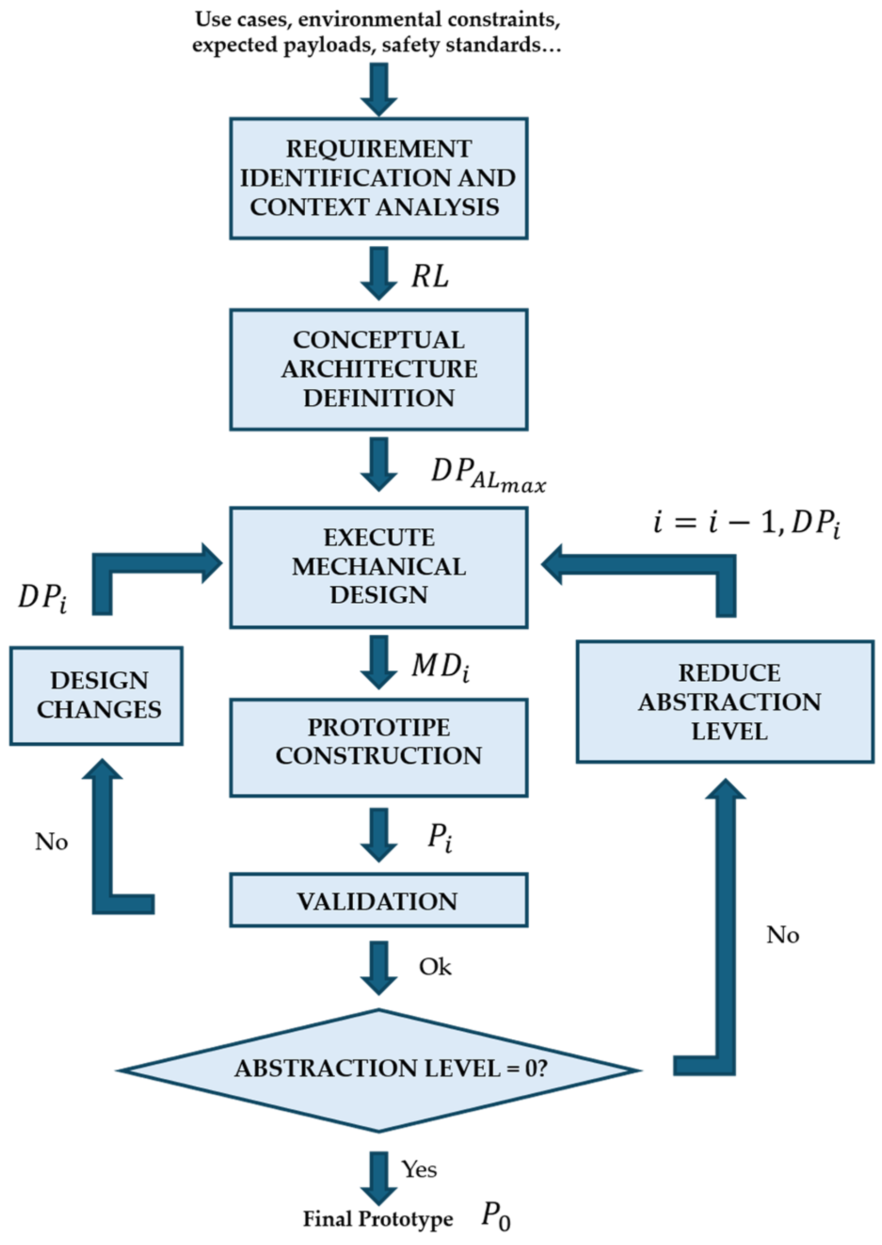
Unlike purely sequential design approaches, the proposed framework formalizes the design process as an iterative loop governed by abstraction levels, where successive design proposals progressively evolve from high-level concepts to fully validated physical prototypes. The overall workflow is illustrated in Figure 1.
The methodology starts from an explicit Requirement List ( R L ) derived from use cases and contextual constraints, and iteratively generates and validates design proposals ( D P i ), mechanical designs ( M D i ), and physical prototypes ( P i ), until the abstraction level is fully resolved and the final prototype ( P 0 ) is obtained.
Each stage of the framework is defined in terms of inputs, outputs, and decision criteria, ensuring traceability and reproducibility throughout the design lifecycle.
Each stage is defined in terms of inputs, outputs, and design objectives, in order to facilitate its application to different robotic platforms.
  • Stage 1. Requirement Identification and Context Analysis
The framework starts with the system definition stage, where both functional and operational requirements are collected and structured.
  • Inputs: target use cases, environmental constraints, expected payloads, safety standards, and integration requirements.
  • Outputs: a comprehensive requirement specification document ( R L ) that defines design limits and performance indicators.
Key aspects include:
  • Defining mission objectives and target tasks.
  • Quantifying load, stiffness, workspace, and reach requirements.
  • Establishing safety margins following ISO 10218 and ISO/TS 15066.
  • Identifying interoperability constraints with AMRs, conveyors, or perception systems.
  • Stage 2. Conceptual Architecture Definition.
This stage transforms abstract requirements into a conceptual architecture of the robotic platform.
  • Inputs: requirement list ( R L ) and environmental constraints.
  • Outputs: Conceptual architectural definition and an initial set of design proposals D P A L m a x corresponding to the highest abstraction level, A L m a x .
At this stage, the system’s global architecture is outlined. The main objectives are to:
  • Select candidate robotic manipulators and determine their relative positioning, ensuring workspace overlap and minimizing interference.
  • Define the support structure geometry, including height, footprint, and accessibility.
  • Select preliminary materials and joining strategies (e.g., extruded aluminum profiles for modularity, welded steel for strength).
  • Explore modular configurations for future adaptability.
Conceptual evaluation tools, digital mock-ups, reachability maps, or ergonomic analyses are recommended to validate feasibility before moving to detailed design.
  • Stage 3. Detailed Mechanical Design and Structural Analysis.
The core of the methodology lies in an iterative mechanical design loop, explicitly governed by the abstraction level A L i .
For a given iteration i :
  • Inputs: design proposal ( D P i ) for the current abstraction level, A L i
  • Outputs: mechanical design instance ( M D i ).
Using CAD and simulation tools, the design proposal is translated into a consistent mechanical model by:
  • Optimize mass distribution and center of gravity for stability.
  • Conduct finite element analyses (FEA) to assess stiffness and stress concentration, and real testing when feasible.
  • Design of subsystems such as conveyors, lifting mechanisms, or cable routing paths.
  • Definition of a fixed space for sensors, actuators, and computing units.
If the resulting mechanical design does not satisfy design constraints or validation criteria, design changes are introduced, generating an updated design proposal ( D P i ) and restarting the iteration at the same abstraction level.
  • Stage 4. Prototype Construction and Assembly.
The mechanical design ( M D i ) at the current abstraction level is used to construct the corresponding physical prototype, P i .
  • Inputs: mechanical design ( M D i ).
  • Outputs: physical prototype ( P i ).
Prototyping activities include:
  • Manufacturing and assembly of full or partial prototypes, depending on the abstraction level.
  • Select materials based on trade-offs between stiffness, weight, and cost.
  • Verification of manufacturability and assembly tolerances.
  • Verify the integration of electrical, pneumatic, and communication systems within the mechanical frame.
  • Stage 5. Validation and Iterative Refinement.
Each prototype ( P i ) undergoes a structured validation process.
  • Inputs: physical prototype ( P i ).
  • Outputs: Validation outcome (Yes/No) and new design proposal for design improvement or abstraction reduction, D P i .
Typical evaluations include:
  • Static and dynamic load testing to ensure the frame remains within elastic limits [26,27].
  • Vibration and deflection analysis under representative manipulation motions [28,29].
  • Stability and rollover assessments, verifying that the center of gravity remains within the support polygon [30,31].
  • Functional testing with manipulators and payloads to confirm accessibility and safety [32].
If validation is successful, a decision is made regarding the abstraction level:
  • If A L i > 0 , the abstraction level is reduced ( i = i 1 ), and a new design proposal (( D P i 1 ) is generated with increased design fidelity.
  • If A L i = 0 , the design process converges to the final validated prototype ( P 0 ).
If validation fails, the process loops back to design proposal modification without changing the abstraction level.

3.1. Quick Reference Guide

To facilitate reproducibility and promote methodological consistency, the following structured checklist summarizes the key checkpoints for each design phase. Each design stage is accompanied by its corresponding evaluation goals and a set of guiding questions. This list helps designers to trace requirements, assess design maturity, and ensure completeness across all development stages of the robotic platform.
1. 
Requirements
Goals:
Establish measurable functional and safety boundaries that guide all subsequent design decisions; formalize operational and environmental assumptions for reproducibility.
Guiding Questions:
  • Have the payload, reach, and stiffness targets been quantitatively specified?
  • Are cycle time, positioning accuracy, and repeatability requirements defined?
  • What environmental conditions (temperature, vibration, humidity) must the structure withstand?
  • Which international standards and safety directives (ISO 10218-2, ISO/TS 15066, CE marking) apply?
  • Are human–robot interaction constraints, such as contact forces and protective distances, clearly established?
  • Has interoperability with AMRs, conveyors, or external controllers been considered?
  • Are measurable Key Performance Indicators (KPIs) defined for later validation?
2. 
Conceptual Design
Goals:
Define a coherent mechanical architecture that balances reachability, compactness, and modularity while ensuring ergonomic compatibility and task feasibility.
Guiding Questions:
  • Are the manipulators adequately selected for the payload, reach, and dexterity required by the target tasks?
  • Do both arms achieve sufficient workspace overlap for cooperative manipulation?
  • Is the structure compact, accessible, and modular for the defined tasks?
  • Is the geometry compact enough for navigation and accessibility?
  • Are accessibility and maintenance zones clearly defined?
  • Are anthropomorphic considerations (height, reachability for human co-workers) integrated?
  • Does the proposed concept allow modular extensions or reconfiguration for future use cases?
3. 
Material and Structural Design
Goals:
Validate that the mechanical structure satisfies stiffness, strength, stability, and longevity requirements; confirm that material selection supports durability, modularity, and compliance with safety factors.
Guiding Questions:
  • What material combinations best balance stiffness, mass, and manufacturing cost?
  • How will loads and vibrations be absorbed and distributed?
  • Is the center of gravity always inside the support polygon?
  • Are welds, bolted joints, or modular extrusions appropriately dimensioned?
  • Has finite element analysis (FEA) confirmed that stresses remain below allowable limits under static and dynamic loads?
  • Have fatigue, wear, and corrosion effects been considered for long-term use?
  • Is the design compliant with industrial safety factors (>1.5 under maximum load)?
4. 
Integration
Goals:
Demonstrate manufacturability, maintainability, and interoperability; guarantee that the assembled system can be safely operated, serviced, and upgraded with minimal redesign.
Guiding Questions:
  • How are cables, power lines, and controllers routed and protected?
  • Are the power, data, and pneumatic/hydraulic lines safely routed and accessible for maintenance?
  • Are electromagnetic compatibility (EMC) and grounding strategies incorporated?
  • Have standardized electrical and mechanical interfaces been defined for sensors, actuators, and controllers?
  • Are accessibility and safety preserved during assembly and disassembly?
  • Have ergonomic factors for operators (height, reach, tool access) been reviewed?
5. 
Validation
Goals:
Provide experimental evidence of compliance with design specifications; close the design loop through quantitative correlation between analytical models and empirical data, ensuring readiness for real-world deployment.
Guiding Questions:
  • Does the structure remain within the elastic range under maximum static and dynamic loading?
  • Has rollover stability been tested for the most critical arm configurations?
  • Can the platform be safely lifted, transported, and mounted on different AMR bases if needed?
  • Do experimental deflection measurements remain within the specified limits?
  • Are test logs, torque monitoring, and deformation data recorded for traceability?

3.2. Recommended Tests

To ensure that robotic platforms meet the required standards of mechanical robustness, stability, and operational safety, a set of standardized tests is recommended prior to prototype deployment. These tests, summarized below, provide a methodological framework applicable to any modular robotic structure intended for mobile manipulation.
1. 
Static Load Tests
Objective: Evaluate the capacity of the structural frame to support its nominal payload without exceeding elastic deformation limits.
Methodology: Apply uniformly distributed and concentrated loads corresponding to 1.0–1.5 times the rated payload for periods of 24 h (short-term) and 7–20 days (long-term).
Acceptance criteria: The maximum allowable deflection is defined by the classical beam design criterion (Equation (1)), widely adopted in mechanical and structural engineering handbooks such as Shigley’s Mechanical Engineering Design [27] and Mechanics of Materials [33]:
δ m a x = L 250
Here, δ m a x is the maximum deflection tested, and L is the length of the platform. No yielding or permanent deformation shall occur.
Typical instrumentation: calibrated torque wrench (25–50 Nm range) and dial gauges (0.01 mm precision).
2. 
Dynamic Load Tests
Objective: Assess the structural integrity of joints and fasteners under cyclic or vibration-induced stresses that simulate real operating conditions.
Methodology: Subject the loaded platform to repeated acceleration-deceleration cycles (0.2–0.5 g) on ground-supported and AMR-mounted configurations, monitoring torque variation before and after testing.
Acceptance criteria: Torque variation is evaluated using the criterion shown in Equation (2) [34].
τ a f t e r τ b e f o r e τ b e f o r e × 100 5 %
And no crack initiation or residual displacement was observed.
It should be noted that the relative importance of static and dynamic analyses strongly depends on the intended operational profile of the robotic platform. For applications involving slow, infrequent, and quasi-static manipulation tasks, static load, deflection, and material yielding analyses typically represent the dominant design constraints, as gravitational and payload-induced loads prevail over inertial effects.
Conversely, for platforms intended to perform fast, repetitive, or highly dynamic motions, inertial forces associated with rapid accelerations and decelerations of the manipulators and payload may significantly increase the stresses transmitted to the supporting structure. In such cases, dynamic effects should be explicitly considered as part of the recommended test methodology, either through time-dependent dynamic simulations or by conservatively incorporating inertial loads derived from worst-case trajectories into the structural analysis, as discussed in Section 6.
3. 
Deflection Tests
Objective: Quantify structural stiffness by measuring displacement under static loading.
Methodology: Measure vertical deflection at critical points using dial gauges while applying distributed and concentrated loads equivalent to the nominal payload.
Acceptance criteria: It must be the same as in the recommended test 1 (Equation (1)).
4. 
Material Yielding Analysis
Objective: Verify analytically that induced stresses remain below the elastic limit of the material under the most demanding loading conditions.
Methodology: Compute bending moments and section modulus of the main beams; compare induced stress with the yield strength of the material, applying a recommended safety factor S F   1.5 .
Acceptance criteria: According to Navier’s law for simple flexion and applying a safety factor of 1.5 , the acceptance criteria are shown in Equations (3) and (4).
σ = M y m a x I
σ < σ y S F
5. 
Lifting System Verification
Objective: Validate the mechanical safety of the lifting or docking systems used to transfer the platform between AMRs or maintenance stations.
Methodology: Apply analytical calculations for maximum bending moment on lifting bars and verify experimentally by gradually applying static loads equivalent to S F ×   S W . Being S W the self-weight of the structure.
Acceptance criteria: The maximum bending stress on the lifting bars is calculated in Equations (5) and (6) following standard strength-of-materials relations [27].
σ y = 32 M m a x π d 3
σ m a x = σ y S F
No permanent deformation shall occur.
6. 
Rollover and Stability Tests
Objective: Confirm that the combined center of gravity (CoG) of the platform and manipulators remains within the support polygon under all operational configurations.
Methodology: Determine CoG position via CAD and physical measurements; perform tilt tests by incrementally inclining the base until the onset of tipping; record the critical angle.
Acceptance criteria: The center of gravity projection must remain inside the polygon formed by the supporting legs or AMR footprint [32].
7. 
Fastening and Torque Retention Tests
Objective: Verify the reliability of bolted or modular joints under repeated load cycles and vibration.
Methodology: Record torque before and after 100 load cycles using calibrated torque sensors; evaluate any loss exceeding 5% as a sign of insufficient preload or thread relaxation.
Acceptance criteria: Equation (2) must be verified, as well as no visible loosening, slippage, or cracking at joint interfaces.
The above test set provides a comprehensive methodological framework covering the most critical aspects of mechanical validation: static and dynamic loading, deflection, yielding, lifting, stability, fastening reliability, and environmental robustness. These procedures collectively ensure that the robotic platform satisfies the structural and safety criteria required for real-world operation, in alignment with recognized mechanical engineering standards and current literature.

4. Use Case: Design of Bimanual Robotic Platform Within the MANiBOT Project

4.1. MANiBOT European Project

The proposed framework is validated through its implementation within the European project MANiBOT [13], which aims to advance the physical and cognitive capabilities of collaborative mobile manipulators for real-world applications. MANiBOT serves as an exemplary context to demonstrate the methodology in practice, encompassing demanding scenarios such as:
  • Autonomous shelf restocking in supermarkets, involving bimanual manipulation in human-populated and confined spaces.
  • Airport baggage-handling operations, requiring robust, safe, and efficient loading and unloading between conveyor belts and carts.
To this aim, it is critical to design a flexible robotic platform able to transport collaborative robots for dexterous bimanipulation tasks [9].

4.2. Functional Requirements of the Robotic System

The design of the MANiBOT platform was driven by a set of functional requirements derived directly from the operational scenarios defined for supermarket restocking and airport baggage handling. Although these domains differ in layout and workflow, both impose demanding mechanical constraints on the robotic system: manipulation of objects with varied mass and geometry, operation in confined and cluttered spaces, and physical interaction with shelves, carts, and conveyors.
From the analysis of these environments, the requirements essential for guiding the mechanical architecture of the platform were identified. These requirements focus exclusively on the physical capabilities, structural performance, and layout characteristics needed to ensure safe, stable, and reliable manipulation in real conditions. The critical functional requirements are the following:
  • Dual-arm integration and coordinated operation: the platform must support the installation of two collaborative manipulators capable of performing coordinated bi-manual tasks. The mechanical frame must provide rigid and precise mounting points that guarantee repeatable positioning and alignment.
  • Adequate workspace and arm overlap: the structure shall enable both manipulators to reach shared and individual workspaces, ensuring sufficient overlap for hand-over actions and cooperative manipulation. This includes maintaining clear, unobstructed areas around shelves, carts, and conveyor interfaces.
  • Conveyor system accommodation: the platform must incorporate a conveyor subsystem, mechanically integrated into the frame, enabling object transfer between the environment and both arms. The mechanical design must ensure stability during loading/unloading and allow configurations such as tilting or height variation.
  • Structural rigidity and payload endurance: the frame must maintain elastic, deformation-free behavior when subjected to payloads up to 11 kg per arm at maximum reach, including the additional forces arising from dynamic movements or bi-manual lifting.
  • Stability when mounted on mobile bases: the combined structure—manipulators, conveyor, and payload—must preserve static and dynamic stability when installed on different AMR platforms. This includes resisting tipping when the conveyor is inclined or when arms operate asymmetrically.
  • Modularity, accessibility, and maintainability: the mechanical design shall be modular, allowing easy assembly, reconfiguration, and servicing. The structure must include accessible panels, ventilation paths, and protected internal routing for cables and auxiliary systems.
  • Dedicated internal space for equipment: the platform must reserve adequate, mechanically protected internal volume for computing units, controllers, power electronics, and communication hardware. This includes ensuring organized cable routing and avoiding interference with arm workspaces.
  • Geometric symmetry and balanced mass distribution: the upper structure shall follow a symmetrical layout to ensure balanced load distribution, reduce torsional stresses on the frame, and simplify dynamic behavior when mounted on an AMR.
Collectively, these mechanical requirements establish the foundation for the platform’s structural design and drive the engineering decisions taken throughout the conceptual and detailed design stages. They ensure that the MANiBOT platform is physically capable of performing the intended tasks in realistic retail and airport environments, supporting reliable bi-manual manipulation and stable interaction with shelves, carts, and conveyors.

4.3. Scenarios

To ground the functional requirements in real practice, the MANiBOT consortium identified four industrially significant and operationally demanding scenarios. These cover collaborative manipulation tasks in unstructured retail and airport domains, characterized by diverse object types, limited workspaces, and constant human presence. Each SC is broken down into detailed sub-scenarios (Sub-SCs), mapping the sequence of robotic actions required to accomplish the task.

4.3.1. Scenarios 1 and 2: Product Restocking in Retail Environments

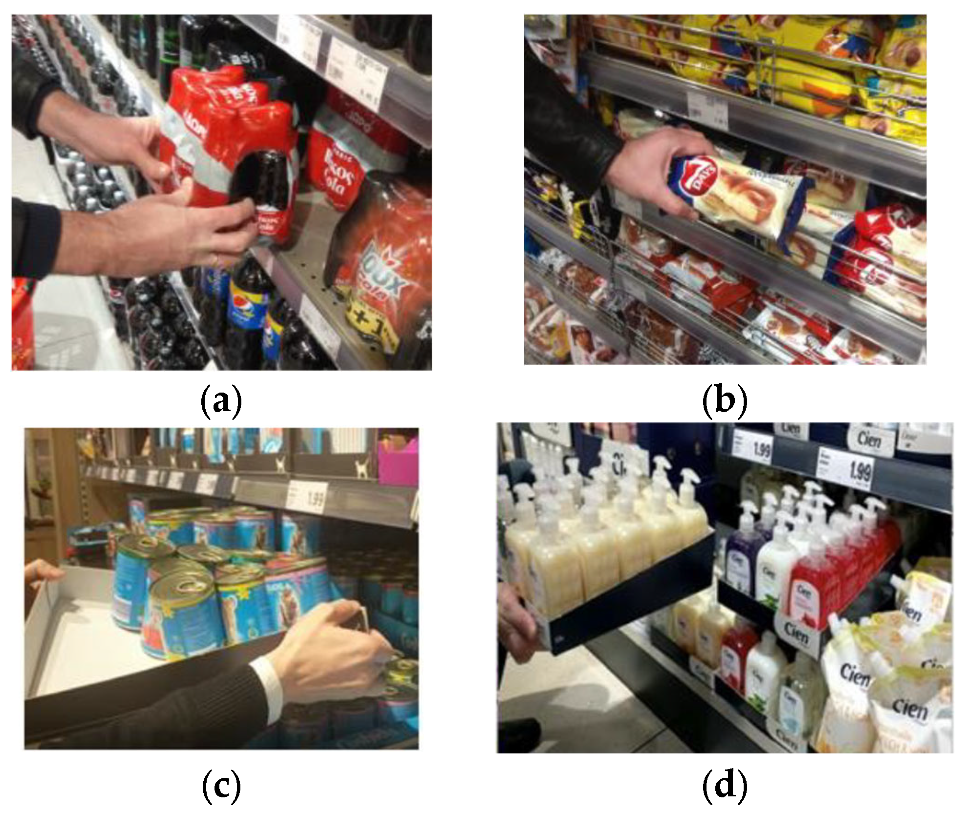
The first two scenarios address automated product restocking in supermarket and pilot-shop settings. In both situations, the robot must operate in confined spaces, interact physically with a wide variety of items, and execute manipulation sequences that involve picking, orienting, and placing products onto shelves.
In Scenario 1, products are supplied on a conventional replenishment cart, while Scenario 2 extends this context to mixed pallets, where goods may arrive in heterogeneous packaging such as shrink-wrapped bundles or plastic crates. In both cases, the robot must correctly extract each item, manage its placement according to store-specific criteria (including FIFO policies when required), and perform the shelf arrangement in a stable and repeatable manner.
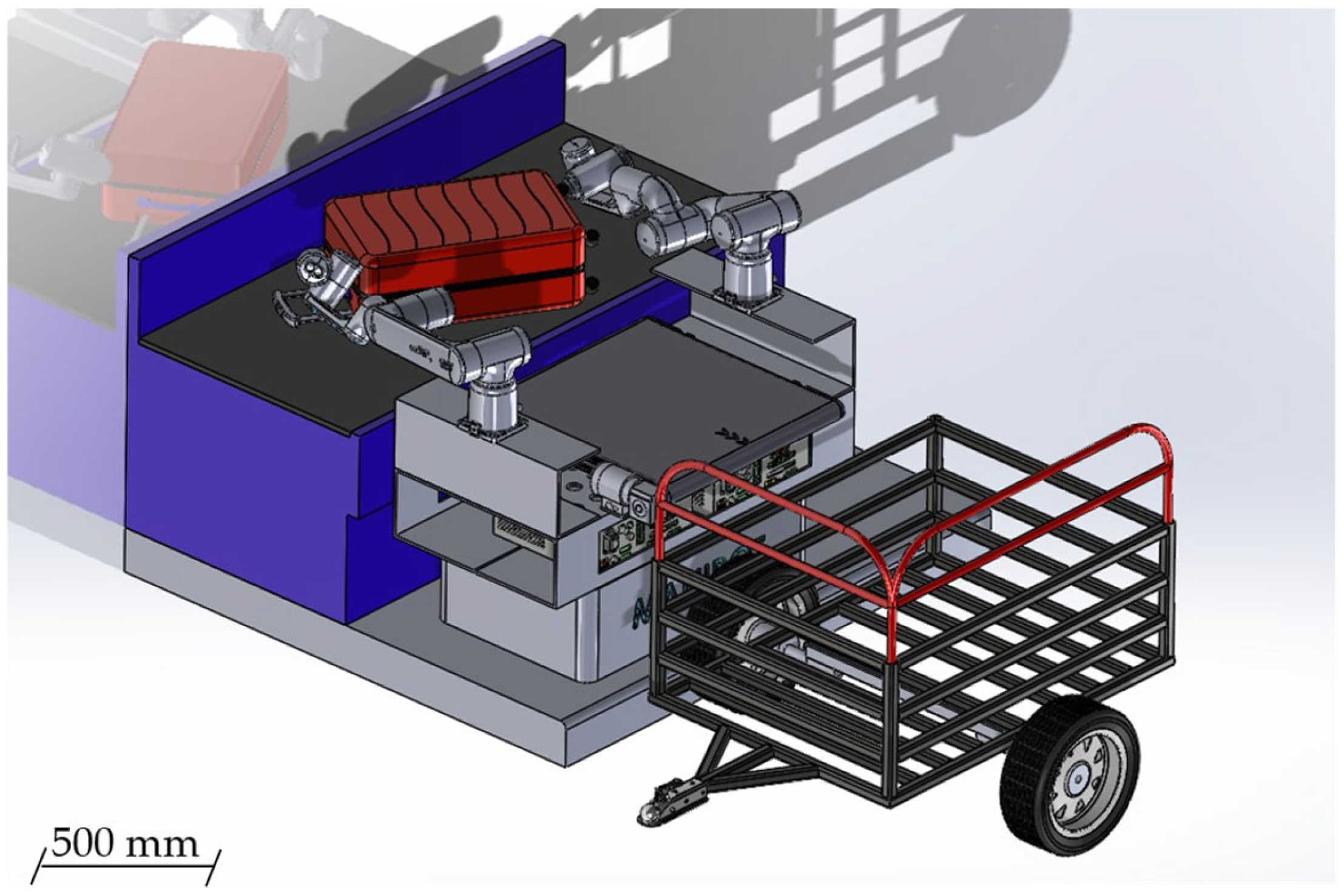
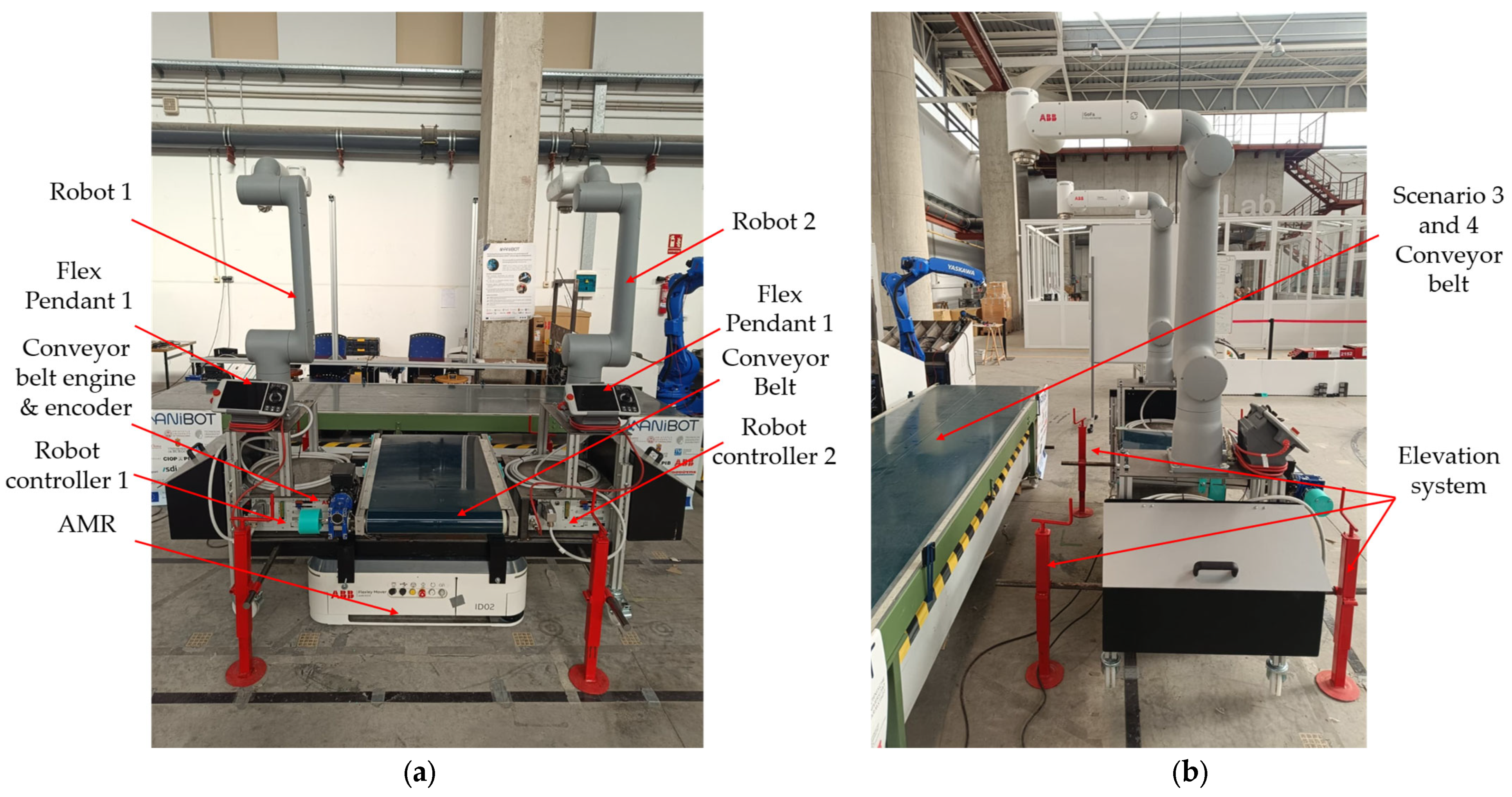
These scenarios emphasize the mechanical and operational demands placed on the platform: coordinated bi-manual actions, safe manipulation close to shelves and customer areas, and the ability to handle items of different sizes, orientations, and rigidity without requiring a redesign of the robotic structure. They serve as a benchmark to validate the platform’s reach, stability, task execution workflow, and integration with real retail layouts (Figure 2).

4.3.2. Scenarios 3 and 4: Airport Baggage Loading and Unloading

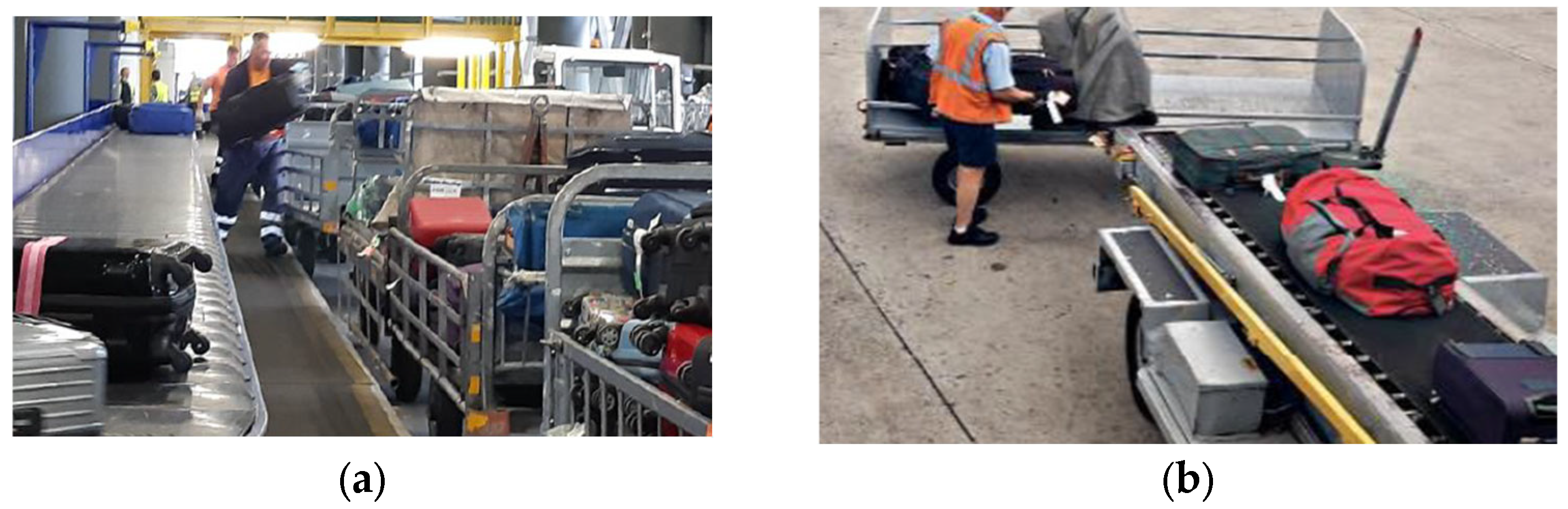
Scenarios 3 and 4 address complementary luggage-handling operations in an airport environment. Scenario 3 focuses on loading suitcases from a conveyor belt onto a transport cart, requiring the robot to interface physically with both fixed and mobile airport infrastructure while manipulating luggage of varying mass, geometry, and deformability. The robot must grasp each item securely, reorient it when required, and place it in a stable and ordered arrangement inside the cart, ensuring efficient use of space and proper load distribution. This operation serves to validate the structural rigidity of the platform, the effective workspace of both manipulators, and the coordination needed for bi-manual handling, particularly when managing large or heavy items.
Scenario 4 extends this evaluation by addressing the reverse operation: unloading luggage from the cart and depositing it onto a conveyor belt. In this phase, the robot must extract items from partially filled carts, avoid contact with surrounding structural elements, and ensure that each suitcase is positioned correctly before release. Additionally, the scenario includes moving between different carts and returning to the initial location, which helps assess the platform’s compatibility with typical airport layouts and its ability to support uninterrupted task sequences.
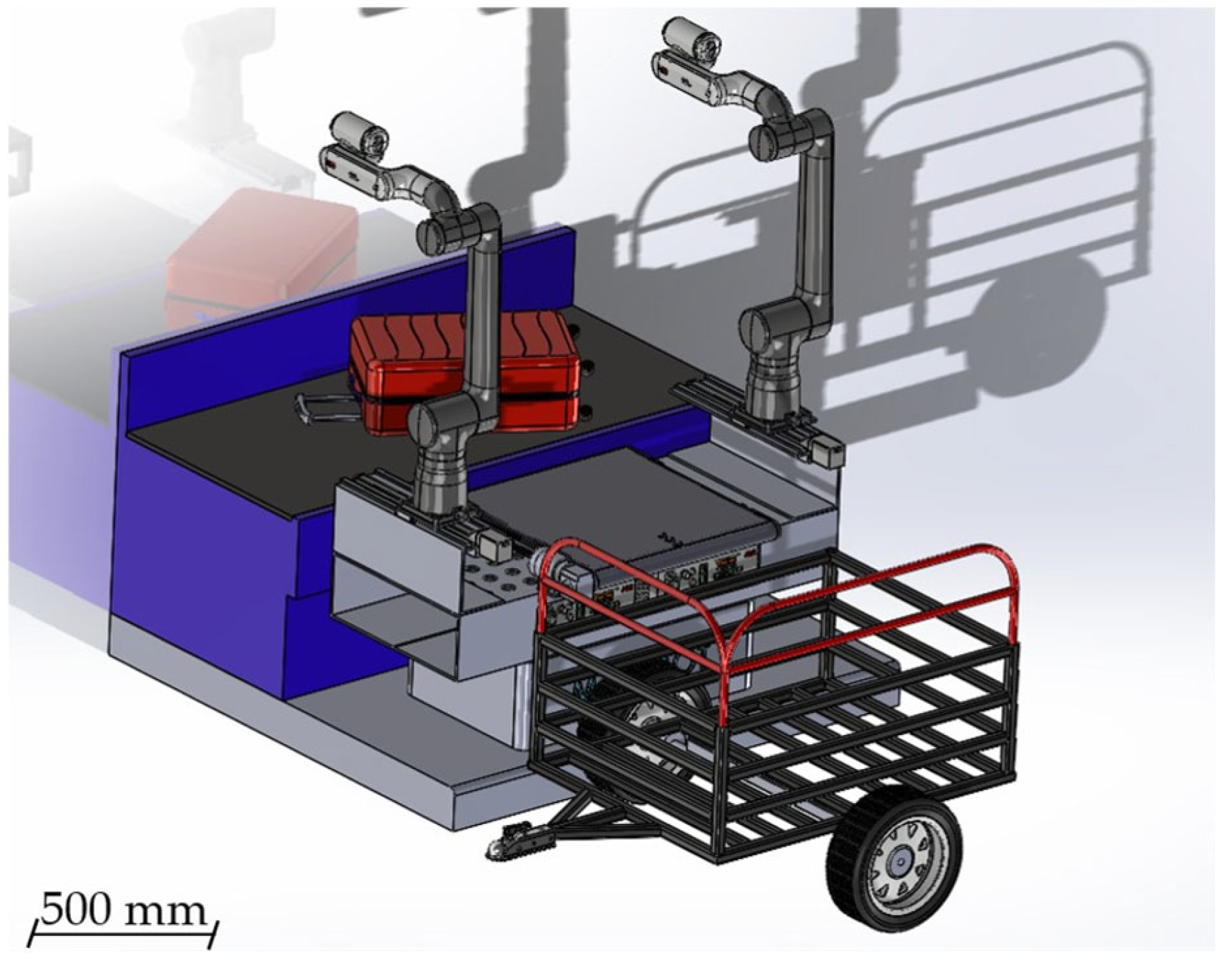
Together, these two scenarios provide a comprehensive assessment of the platform’s capacity to execute repetitive, physically demanding manipulation tasks in realistic airport workflows (Figure 3).

5. Application of the Design Methodology to the Use Case

This section demonstrates the practical implementation of the methodology presented in Section 3 through its application to the MANiBOT robotic platform. The process followed the cyclic workflow illustrated in Figure 1, evolving from requirement identification to the validation of a fully functional prototype. The test protocols and quantitative results of the validation campaign are presented in Section 7.

5.1. Stage I—Requirement Identification and Context Analysis

The MANiBOT platform was conceived to operate in two demanding, real-world domains: supermarket shelf restocking and airport baggage handling. From these scenarios, a set of functional and operational requirements was derived, forming the foundation of the design process.
In accordance with systems-engineering principles, the requirements were classified into Functional Requirements (FR) and Operational Requirements (OR).
Functional requirements describe what the system must do—that is, the intrinsic capabilities, behaviors, and design features needed to fulfill its intended tasks.
Operational requirements, in contrast, define under what conditions and constraints the system must operate, including environmental, regulatory, and maintainability aspects.
This distinction provides a clear structure for translating high-level mission objectives into verifiable engineering specifications, ensuring that both the internal functionality of the platform and its interaction with real-world environments are consistently addressed.
The MANiBOT robotic platform’s Functional Requirements are as follows:
  • FR1—Dual-arm capability: The platform shall host two collaborative manipulators enabling coordinated bimanual operation.
  • FR2—Workspace overlap: The manipulators shall provide sufficient workspace overlap to enable cooperative tasks and safe handover operations.
  • FR3—Conveyor subsystem integration: The structure shall include a conveyor system allowing coordinated object transfer between manipulators or external stations.
  • FR4—Structural rigidity under payload: The mechanical frame shall maintain elastic behavior under payloads up to 11 kg per arm at maximum reach.
  • FR5—Stability on AMR base: The system shall preserve static and dynamic stability when mounted on autonomous mobile robots (AMRs), including tilting conveyor configurations.
  • FR6—Modularity and maintainability: The platform shall support modular assembly and easy access for servicing, ventilation, and subsystem replacement.
  • FR7—Allocation of internal components: Adequate internal space shall be reserved for computing units, controllers, and sensors, ensuring organized cable routing and protection.
  • FR8—Symmetry and balance: The overall design shall maintain a geometrically symmetrical configuration to simplify control, equalize loads, and minimize torsional stresses.
On the other hand, the following Operational Requirements for the MANiBOT robotic platform have been identified:
  • OR1—Spatial validation and AMR adaptability: The footprint and mounting interface shall be compatible with multiple AMR bases (e.g., P204, P604) while preserving geometric stability.
  • OR2—Working height and task range: The manipulators and conveyor shall jointly enable operation between 0.5 m and 2.5 m, covering all expected manipulation heights.
  • OR3—Safety and regulatory compliance: The design shall conform to collaborative-robot standards, including [11,12], ensuring safe human–robot coexistence.
  • OR4—Maintainability and service access: The platform shall feature accessible panels, guided cable routing, and proper ventilation to facilitate maintenance and minimize MTTR.
  • OR5—Integration of power and computing systems: The platform shall provide sufficient energy capacity and internal integration for computing resources (NUCs, Jetsons, industrial PC), ensuring electromagnetic compatibility (EMC) and operational autonomy.
Together, these requirements define the baseline constraints and performance objectives guiding the conceptual, detailed, and validation stages of the MANiBOT platform, as summarized in Table 1 and later traced across successive design iterations.

5.2. Stage II—Conceptual Design of the Platform: Space Exploration and Initial Configuration

The mechanical development of the MANiBOT platform followed a stepwise, iterative refinement cycle explicitly aimed at aligning the structure with the demanding requirements of retail and airport scenarios. Over twelve main iterations, the system gradually evolved from a purely volumetric concept into a mature, modular, and robust solution ready for experimental validation.
In accordance with the conceptual architecture definition stage, this phase focused on transforming the initial system requirements and environmental constraints into a tangible structural concept. The process explicitly addressed the selection and positioning of manipulators, the geometric definition of the support frame, the preliminary choice of materials and joining strategies, and the exploration of modular configurations to ensure long-term adaptability. Conceptual tools such as digital mock-ups, reachability analyses, and ergonomic evaluations were applied to validate feasibility prior to detailed design.
Version 1—Conceptual volumetric mock-up.
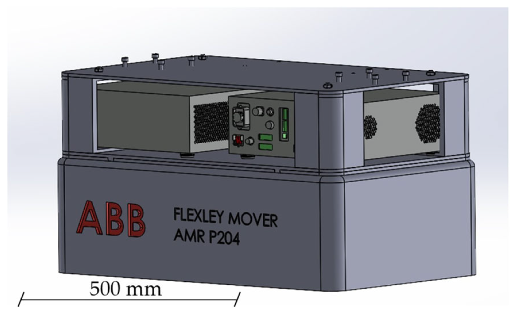
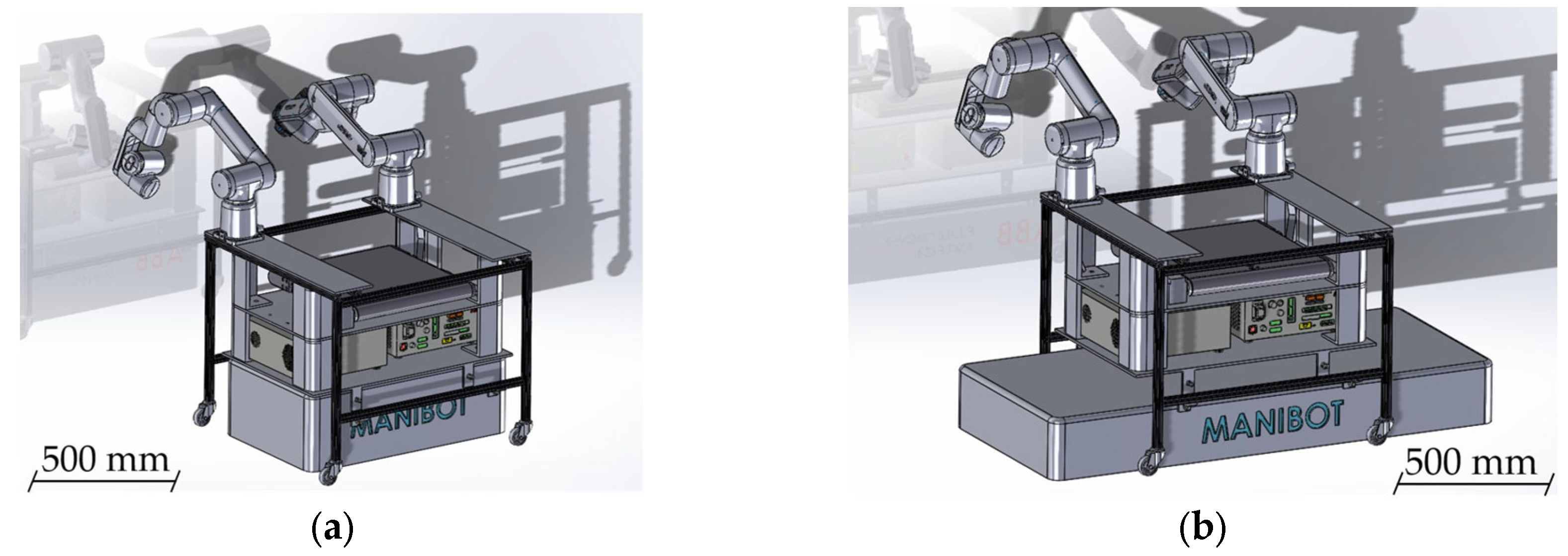
The very first iteration (Figure 4) was conceived as a volumetric envelope corresponding to the P204 AMR footprint. At this stage, the focus was on defining the global geometry of the platform, evaluating height, footprint, and workspace accessibility (Objective II), taking into account that the manipulators will be on top (Objective I), or at least a common solution for the possible ones. Its purpose was not yet to host detailed components, but rather to provide an initial spatial framework for discussing the integration of manipulators, conveyor belts, and auxiliary modules. Reachability maps were generated to verify the potential workspace overlap between future manipulators. At this stage, the search for robotic manipulators was narrowed down to three possible candidates: CRB15000/95, CRB15000/127, and CRB15000/152.
This conceptual model enabled an early evaluation of the physical footprint, highlighted potential constraints for actuator placement, and served as a collaborative reference for aligning design perspectives across project partners.
Version 2—Adaptation to multiple AMR bases.
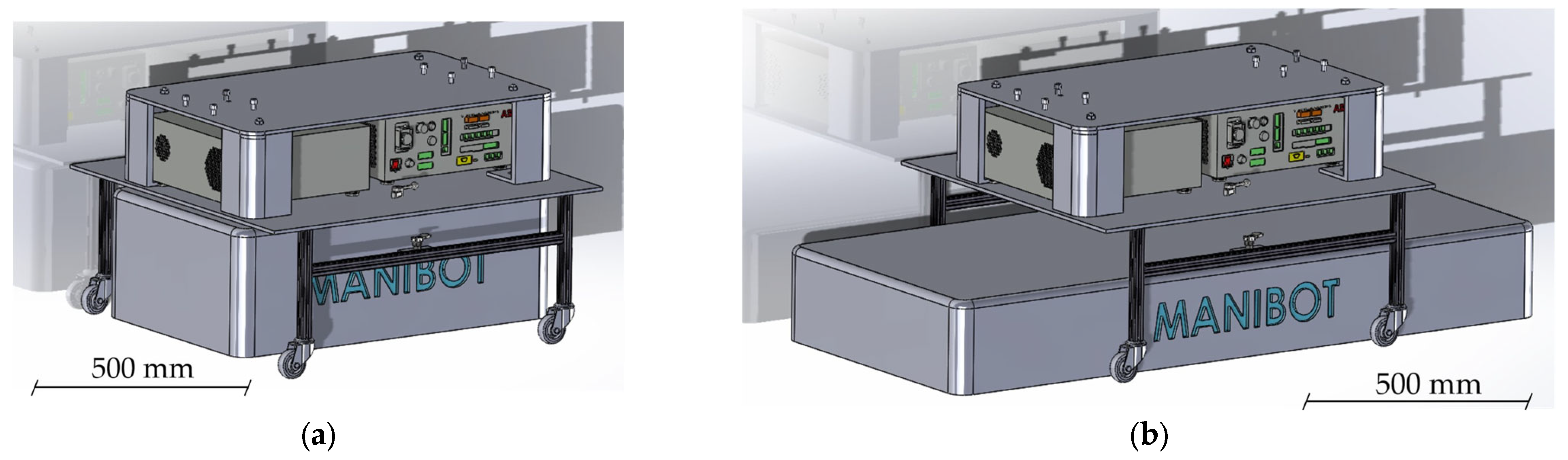
Building upon the volumetric concept, the second design iteration (Figure 5) addressed the need to ensure compatibility with different AMR geometries. The frame geometry was redefined to balance accessibility and stiffness, while an intermediate structure was introduced to guarantee ergonomic working heights (Objective II). A new intermediate frame was introduced as a structural interface, effectively elevating the upper platform while creating an intermediate compartment for cabling and electronics. This modular connection allowed flexible coupling to several mobile bases without compromising rigidity. At this stage, preliminary considerations for ventilation, power interfaces, and service panels were introduced, marking a transition from purely conceptual modeling to functional design. This version directly addressed, for the first time, the requirements of selecting preliminary materials and joining strategies (Objective III) and exploring adaptable configurations for future evolution (Objective IV). Future iterations will be the result of improving these objectives.
Version 3—Extended structure and internal reorganization.
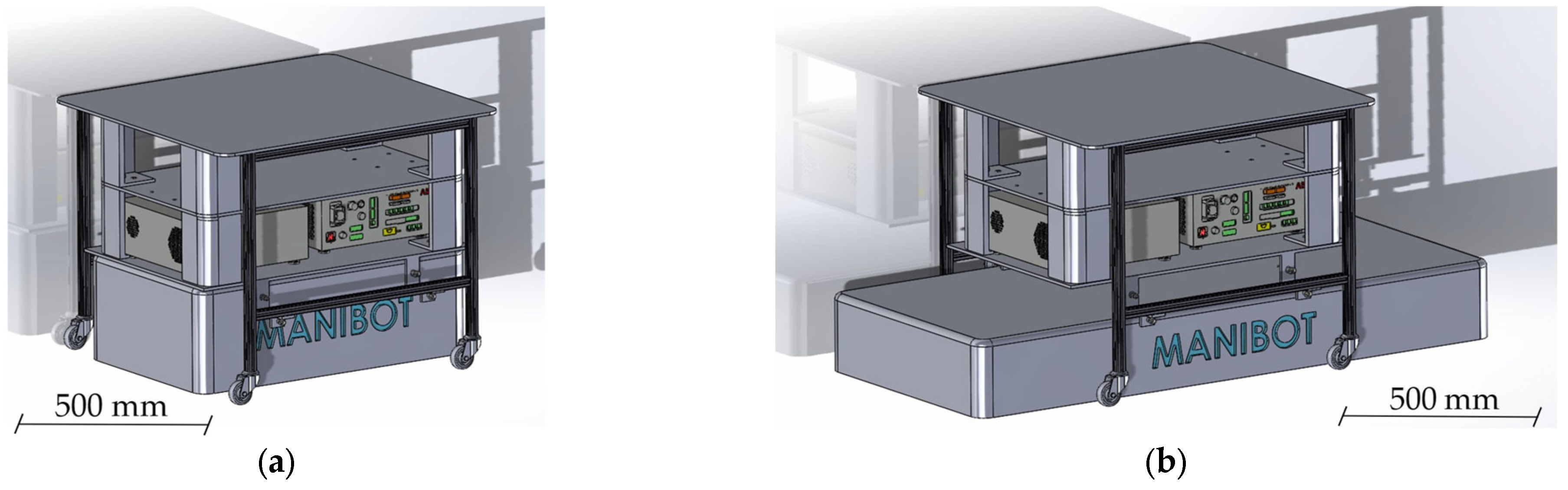
The third iteration (Figure 6) incorporated additional components identified as essential for operability, which required a redefinition of the external dimensions and vertical organization of the platform. This design ensured that the relative positioning of the two temporarily chosen manipulators (CRB15000/95) would provide sufficient workspace overlap while minimizing interference, in direct fulfillment of Objective I. The structure was extended in height, introducing a new upper level envisioned as a potential working surface or mounting point for manipulators and sensors. Internally, compartments were reorganized to improve accessibility to control and communication modules, simplifying future maintenance, while maintaining the modularity (Objective IV).
Version 4—Integration of manipulators and central conveyor.
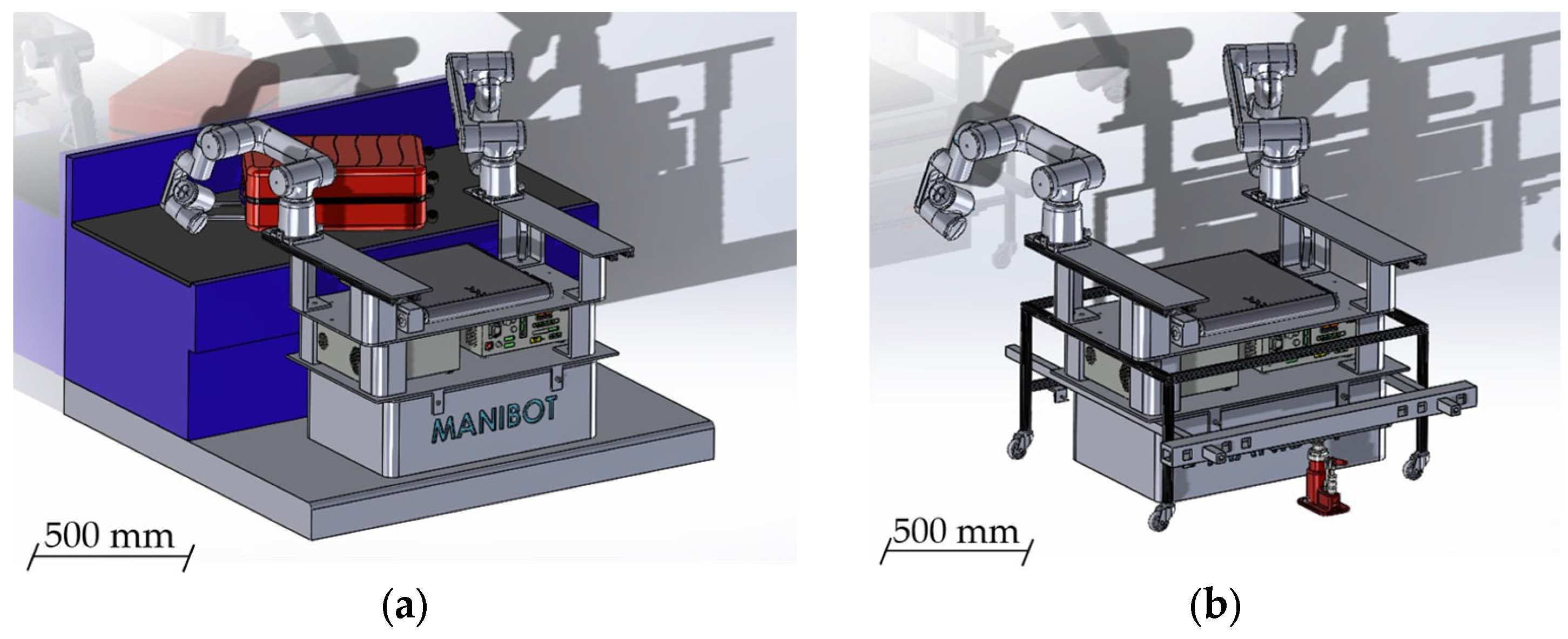
The fourth design iteration (Figure 7) marked the first major step from conceptual modeling to functional prototyping. For the first time, active robotic components were introduced, with two ABB CRB15000/95 manipulators selected as a baseline following the earlier comparative analysis of potential arms (Objective I). Their installation allowed an initial evaluation of dual-arm feasibility, particularly regarding workspace overlap, potential interferences, and collaborative reach. In parallel, a central conveyor belt was incorporated as a placeholder subsystem, enabling early assessment of transfer operations between the manipulators or toward external stations. Although its dimensions were not yet finalized, the conveyor offered valuable insights into accessibility, interaction with moving objects, and workflow organization.
Structurally, this version consolidated anchoring reinforcements (Objective III) and introduced a detachable second level (Objective IV), partially elevating the upper platform to facilitate coupling with multiple AMRs. This modular capability transformed a key principle from earlier iterations into a tangible design feature, while also improving accessibility to control panels and ventilation systems.
Version 5—Virtual integration, structural reinforcement, and lifting system.
The fifth iteration (Figure 8) represented a substantial leap in maturity, as the MANiBOT platform was integrated for the first time into a simulated airport baggage-handling environment. Within this virtual setup, manipulator reach, accessibility, and coordination were validated against a conveyor belt and representative test objects such as suitcases. This virtual integration validated both the global geometry of the support structure and the manipulators’ spatial coordination under realistic constraints (Objectives I and II).
From a mechanical perspective, the structure was redesigned using standardized extruded aluminum profiles, enhancing rigidity while maintaining modularity and compatibility with industrial fastening systems (Objective III). A critical innovation of this version was the introduction of the first lifting system, located at the lower part of the frame, which allowed safe detachment and transfer of the platform between different AMR bases. Together, these advances consolidated the platform as a modular, structurally robust prototype (Objective IV), bridging the gap between conceptual development and operational validation.
Version 6—Sheet-metal feasibility study.
The sixth design iteration (Figure 9) explored an alternative manufacturing pathway based on folded sheet-metal panels. This approach addressed Objective III by testing a different material, and therefore a new joining strategy, that minimized welding while embedding reinforcement features directly into the bending process. Unlike previous profile-based designs, this approach aimed to simplify production, reduce costs, and embed reinforcement features directly into the bending process, thereby minimizing welding and mechanical joints.
Functionally, the layout preserved the core architecture defined in earlier versions: elevated manipulators, a centrally positioned conveyor, front access to electronics, and compatibility with the lifting system. Simulation in the airport scenarios was maintained, ensuring continuity in evaluating interaction with objects and carts. Although conceived as an exploratory branch rather than the definitive design, this version demonstrated the feasibility of transitioning toward pre-industrial manufacturing while preserving all essential functionalities. With this approach, the design lost some modularity (Objective IV was not as fully satisfied as in previous iterations), but it served to verify scalability and manufacturability.
Version 7—Linear system integration and transition to GoFa 12 manipulators.
The seventh design iteration (Figure 10) introduced two decisive advancements: the implementation of linear motion capabilities and the adoption of higher-performance manipulators. Manipulator positioning was revisited to confirm workspace overlap across extended trajectories (Objective I). Mechanically, this version refined the previously explored sheet-metal architecture while equipping one robotic arm with a linear track, substantially extending its operational envelope. This addition enabled the evaluation of tasks requiring longitudinal reach—such as handling distributed objects along a conveyor belt—and provided valuable insights into trajectory planning and kinematic constraints in extended workspaces. Material selection and stiffness calculations were reassessed, confirming the structural feasibility of supporting higher payloads (Objective III).
Simultaneously, the original GoFa 5 manipulator, which was not mounted on the linear track, was replaced with a GoFa 12. This upgrade, motivated by the need to address more demanding payload and reach requirements, allowed the team to perform more realistic simulations involving heavier objects and greater distances from the central platform. As a result, this iteration effectively converged structural robustness, functional flexibility, and workspace analysis, marking a turning point toward readiness for physical prototyping and validation.
Version 8—Consolidated design with folded sheet-metal structure, linear tracks, and GoFa 12 arms.
The eighth iteration (Figure 11) represents the most advanced stage of the sheet-metal-based design pathway and served as the foundation for critical final decisions regarding both structure and manipulation hardware. At this stage, all four conceptual objectives were demonstrably satisfied: (I) optimal dual-arm positioning with minimal interference, (II) a well-defined support geometry balancing footprint, height, and accessibility, (III) material and joining strategies combining folded sheet-metal and bolted reinforcements, and (IV) a modular configuration adaptable to future AMRs and use cases.
Structurally, the geometry was carefully refined for efficient fabrication through bending processes, ensuring rigidity while maintaining lightweight properties. Mounting points, ventilation paths, and access to electronic compartments were systematically addressed, consolidating the design’s maintainability and manufacturability. Functionally, the introduction of two linear tracks allowed each manipulator to extend its workspace significantly, supporting complex collaborative tasks and enabling simultaneous access to multiple zones around the central conveyor. Moreover, the linear motion system was re-engineered into a set of three coordinated elements—one actuator flanked by two supporting linear guides—that together absorb the moments generated at the base of the manipulators. Compared to a single heavy-duty linear track, this configuration provides a much more reliable and cost-effective solution, while still offering the stiffness required to withstand the significant loads induced during extended-reach operations.
The decision to adopt two GoFa 12 arms as the definitive manipulators confirmed the trajectory initiated in the previous iteration, providing the payload, precision, and reach required for the project’s most demanding scenarios. Their integration with the linear tracks produced a highly versatile configuration, capable of addressing both retail and airport scenarios with increased adaptability and operational efficiency.

5.3. Stage III—Detailed Mechanical Design and Structural Analysis

In this stage, the previously defined conceptual architecture was refined into a fully parameterized and manufacturable mechanical system. Using CAD and simulation tools, the design team optimized mass distribution and center of gravity (Objective I), conducted finite element analyses to evaluate stiffness and stress (Objective II), performed dynamic and kinematic simulations to ensure collision-free operation (Objective III), detailed the conveyor and lifting subsystems (Objective IV), and defined interfaces for sensors, actuators, and computing units (Objective V). The outcome of this stage was an optimized CAD model, a complete structural analysis, and an integration plan ready for prototyping.
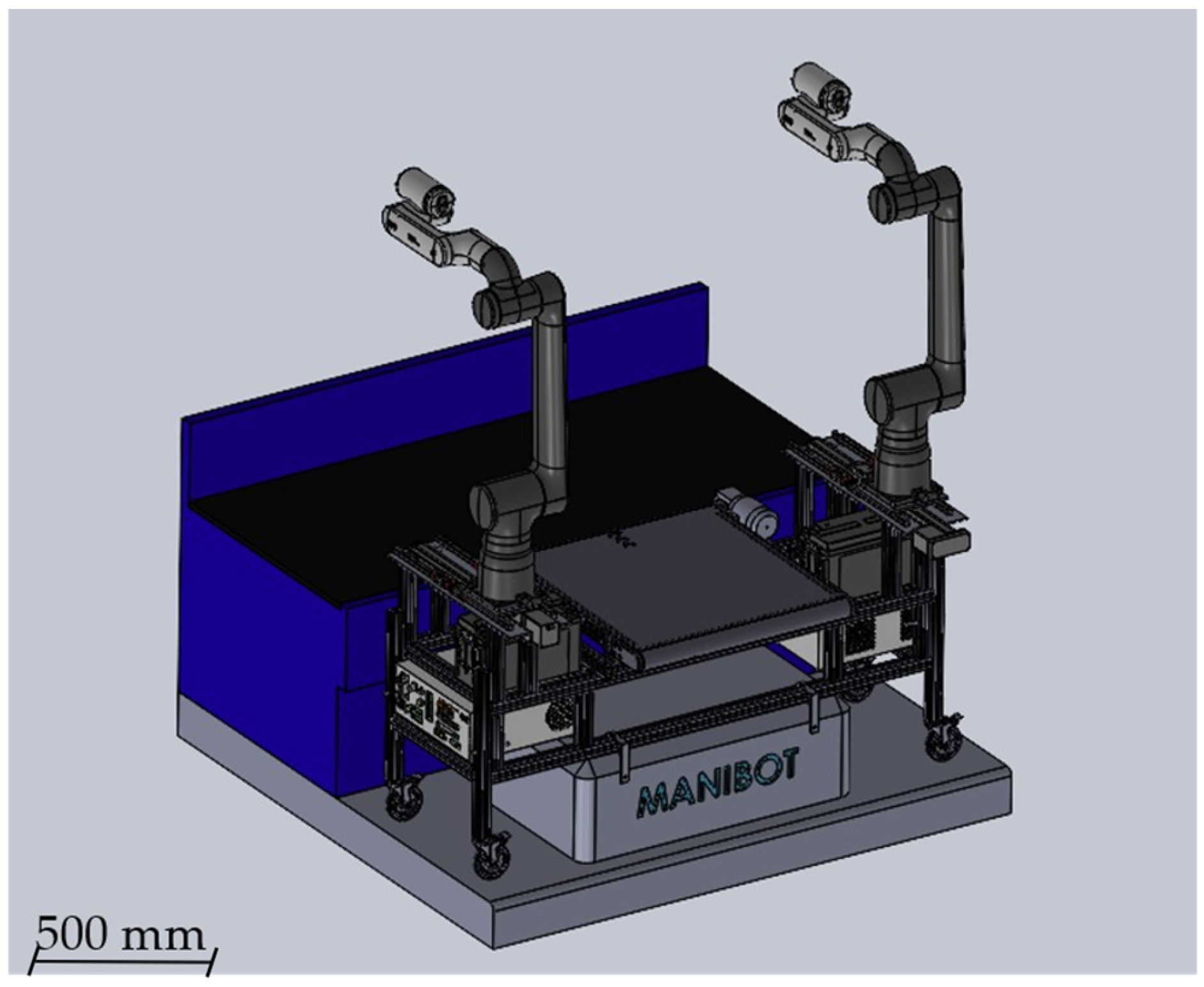
Version 9—Modular architecture with aluminum profiles and optimized linear motion system.
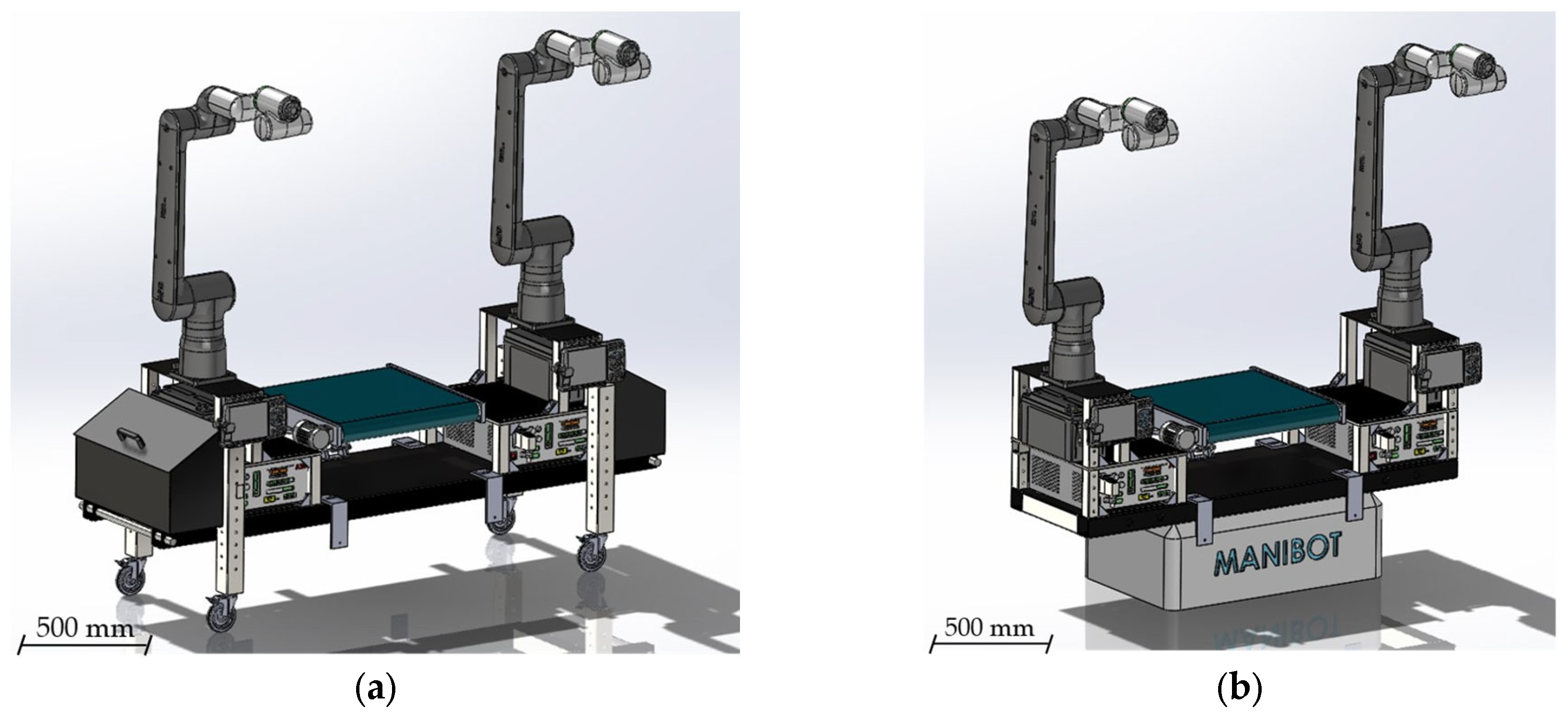
The ninth design iteration (Figure 12) marked a strategic shift toward a fully modular configuration. Departing from the folded sheet-metal concept, this version adopted an extruded aluminum profile structure, enabling a platform that could be easily reconfigured to accommodate different use cases, environments, or future modifications without requiring extensive redesign. The use of standardized profiles provided multiple advantages: reduced weight, high mechanical strength, simplified assembly, and compatibility with widely available industrial fastening systems.
Within this framework, all critical subsystems were integrated for the first time in a coherent assembly: the two GoFa 12 manipulators, the central conveyor belt, and an improved linear track system. The latter was reinforced with dual linear guides, significantly enhancing stability under extended-reach maneuvers and dynamic loads. This redesign ensured accurate positioning of devices, maintaining the center of gravity at the midpoint of the platform by preserving symmetry (Objective I).
Equally important, this version introduced the first functional prototype of the conveyor subsystem, fully embedded into the aluminum frame (Objective III). While still subject to refinements in speed and geometry, it enabled preliminary experiments on coordinated manipulator–conveyor interaction, including luggage-handling scenarios representative of airport operations. In addition, the first reserved spaces for devices and interfaces were incorporated. These elements can be observed in Figure 12, located below the conveyor belt and between the two manipulators (Objective IV). Collectively, these improvements positioned version 9 as a robust, versatile, and highly modular prototype, ideally suited for integration testing and advanced control development.
Version 10—Airport trolley adaptation and conveyor tilting mechanism.
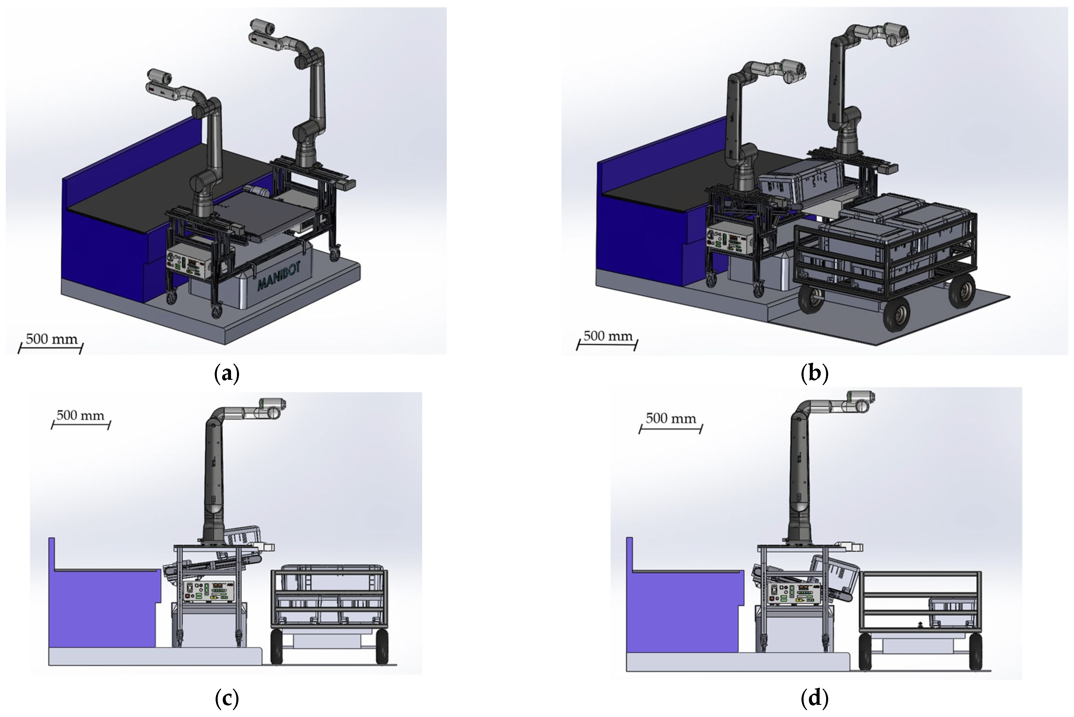
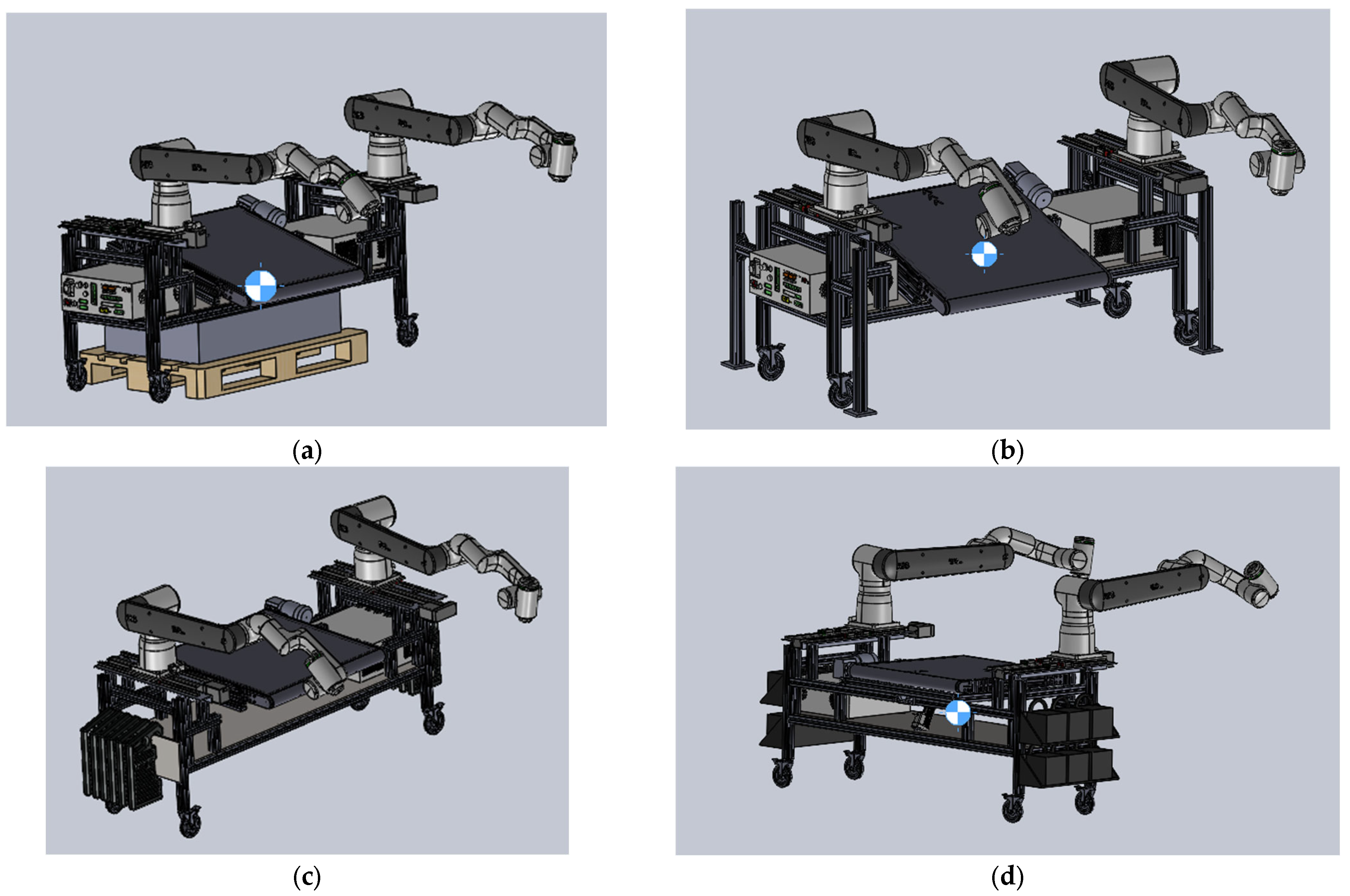
The tenth iteration (Figure 13a–d) addressed one of the most stringent requirements emerging from the airport scenarios: the need to interact with Fraport’s luggage transport carts. The incorporation of precise cart dimensions revealed that the conveyor system had to deliver objects at multiple heights, prompting a significant mechanical redesign.
To meet this requirement, one longitudinal structural bar was removed to accommodate a lateral tilting mechanism for the conveyor (Objective III). This feature enabled controlled unloading at three distinct vertical levels, replicating real baggage-loading conditions inside the airport cart. The conveyor was designed to operate in both horizontal and inclined configurations, ensuring robust alignment with the manipulators’ linear tracks and workspace envelopes.
Structural reinforcements were implemented to preserve stability despite the asymmetrical loading introduced by the inclined conveyor. These reinforcements were calculated through additional FEA simulations (Objective II), verifying that the asymmetric loading introduced by the tilted conveyor did not compromise global stiffness or safety margins. The coordination of the robotic arms with the newly angled surface was also validated through simulations, ensuring safe and precise handling at all levels.
All these changes made it necessary to redistribute the devices (Objective IV), and center-of-gravity adjustments were implemented (Objective I) to maintain stability despite the lateral tilt. With this functionality, version 10 bridged the gap between laboratory prototypes and the operational constraints of the airport environment.
Version 11—Physical validation and transition to steel-reinforced frame.
The eleventh iteration (Figure 14) represented a decisive milestone: the transition from purely digital validation to the first physical prototype. A partial assembly, built from aluminum profiles, was manufactured and tested to evaluate rigidity, stability, and dynamic response under simulated loads (Objective II). These experiments revealed critical limitations in structural stiffness and stability, particularly given the projected increase in total mass once both the manipulators and conveyors were fully integrated. Furthermore, range tests showed that the linear motion of the arms provided only marginal functional benefits relative to their high cost and limited applicability, leading to the strategic decision to discontinue their integration in subsequent designs.
Based on these findings, the design strategy shifted to a reinforced steel-tube frame, providing the robustness and safety margins necessary for real-world deployment. The new structure offered superior load-bearing capacity, improved vibration damping, and a significantly reduced risk of tipping during high-payload operations as the COG is lowered (Objective I).
In parallel, a custom conveyor system was developed and integrated, replacing the generic placeholder models of earlier iterations (Objective III). With an extended width of 1800 mm (Objective IV), this conveyor accommodated larger suitcases and enabled smoother transfer to external carts or conveyors. Together, these modifications brought the platform to a new level of maturity, combining physical test results, structural optimization, and operational alignment with the MANiBOT airport scenario.

5.4. Prototype Construction and Assembly

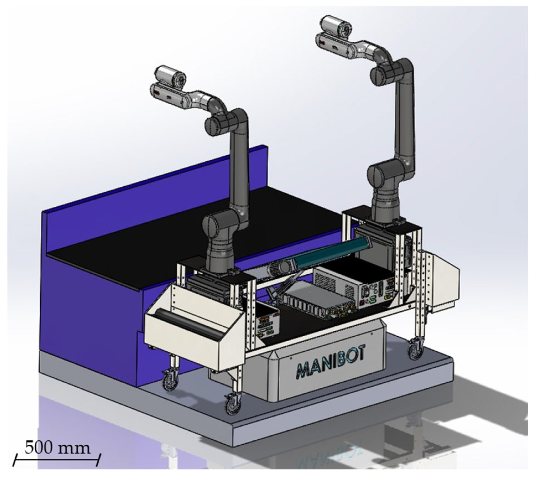
The twelfth and final design iteration (Figure 15) consolidated the MANiBOT platform into a structurally optimized, modular system ready for experimental deployment. Building directly on the limitations observed during physical testing, this version introduced reinforced 80 mm square steel profiles for the primary load-bearing elements. The enlarged cross-section significantly improved stiffness and mechanical robustness, ensuring reliable operation under dynamic conditions such as rapid manipulator movements or payload handling at extended reaches.
A second major innovation of this version was the incorporation of a dedicated lower technical compartment. This newly designed volume provided safe and accessible housing for essential electronics, including power supplies, communication units, controllers, and sensors. By internalizing these subsystems, the platform achieved cleaner cable routing, enhanced protection, and simplified maintenance. In addition, the redistribution of mass toward the lower frame contributed to a lower center of gravity, directly improving stability during mobile operation and interaction with external objects such as luggage carts.
Weighing 437.3 kg, the system guarantees stability against accelerations and dynamic stresses. The center of gravity was deliberately adjusted to reduce tipping risks and improve maneuverability.
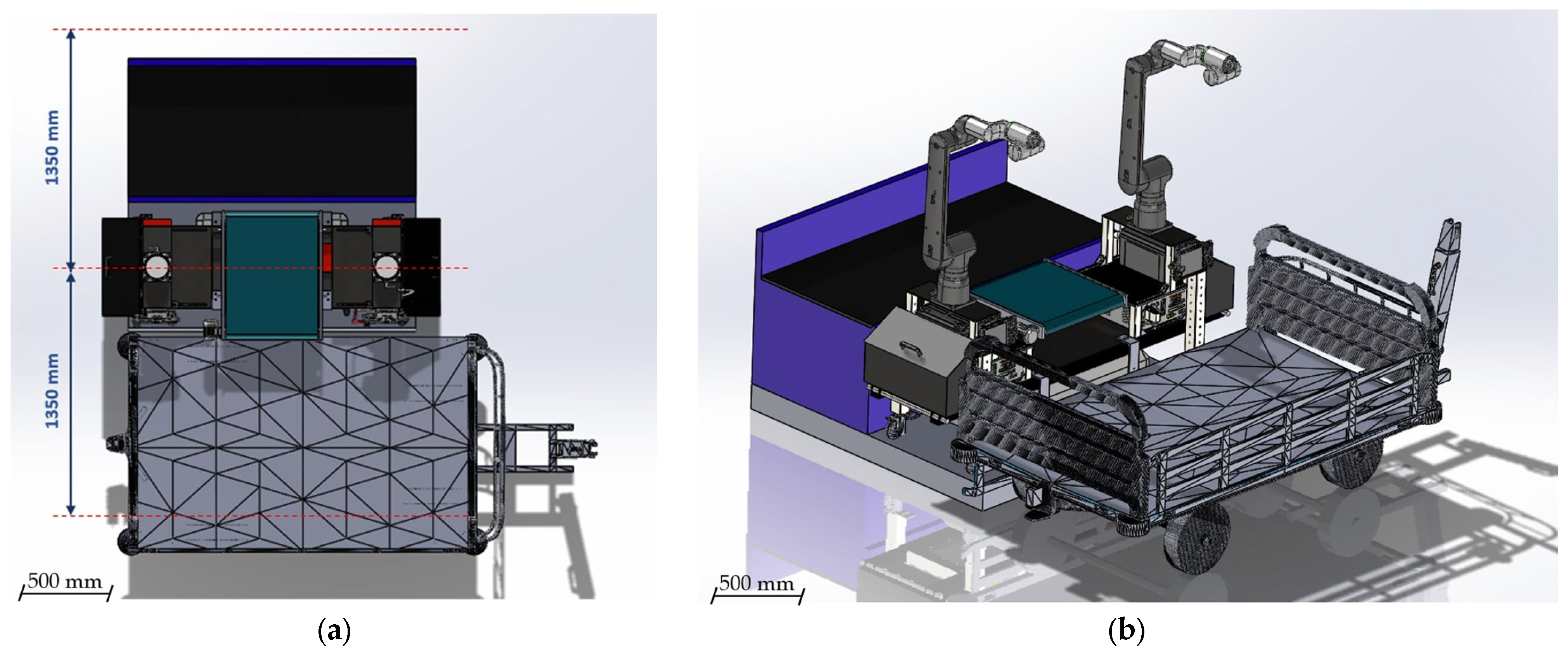
From a workspace perspective, the platform’s geometry was optimized to maximize the overlap of the manipulators’ operational ranges. Both simulations and physical analyses confirmed the absence of collisions during collaborative operations, even when the arms work simultaneously on the same object. Each manipulator can reach up to 1 m beyond the platform boundaries, covering vertical ranges from 0.5 to 2.5 m. This enables the system to interact effectively with carts, conveyors, shelves, and counters at multiple levels.
Furthermore, the design provides dedicated mounting space for all essential computational resources, including three NUCs, two Jetson devices, and one industrial-grade PC, which collectively support the perception, planning, and control layers of the system.
Functionally, the twelfth iteration retained all major advancements from previous versions: the extended-width tilting conveyor, side compartments, and universal AMR mounting interfaces. At the same time, it created new opportunities for scalability, as the technical compartment allows for the integration of additional devices without compromising accessibility or structural integrity.
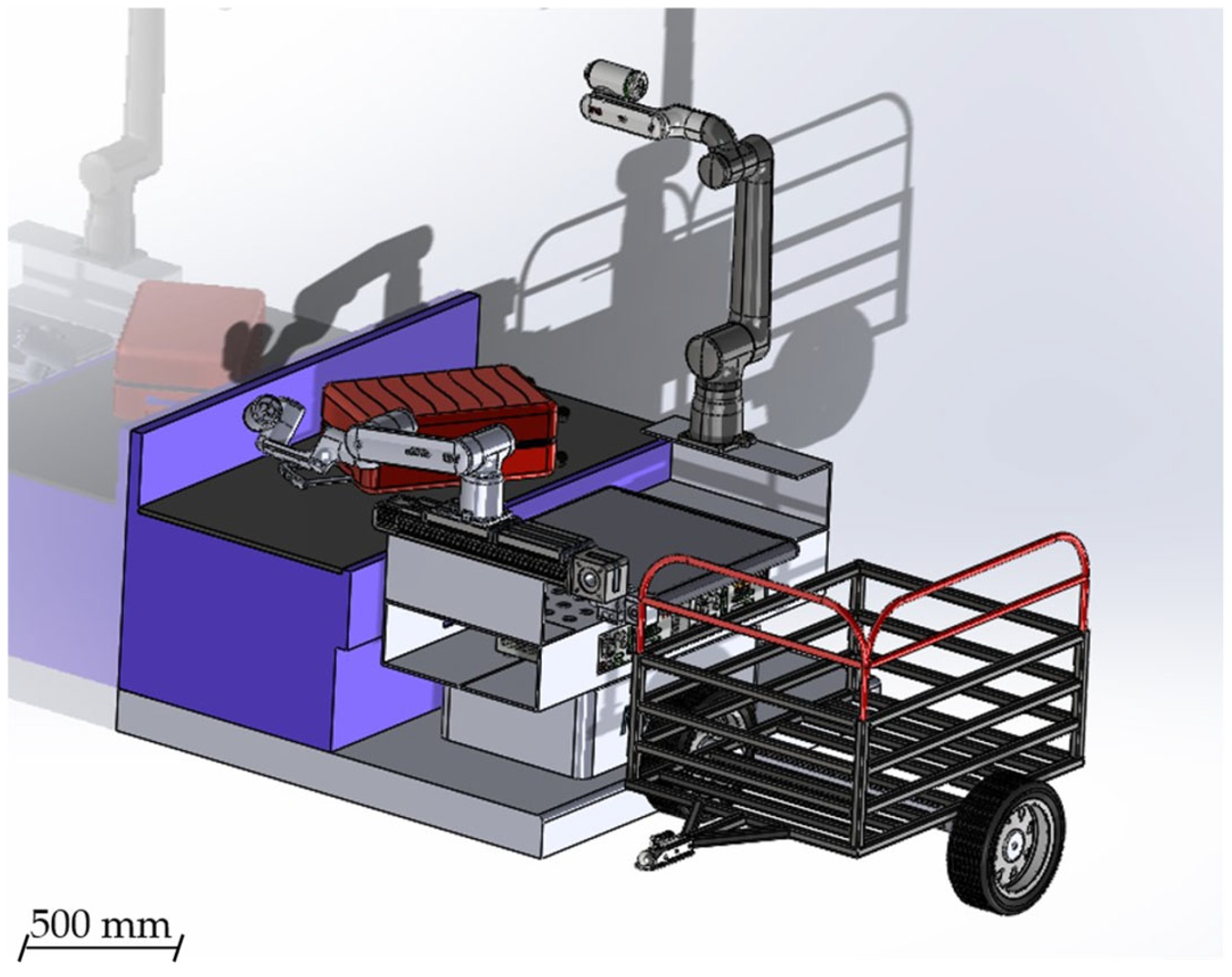
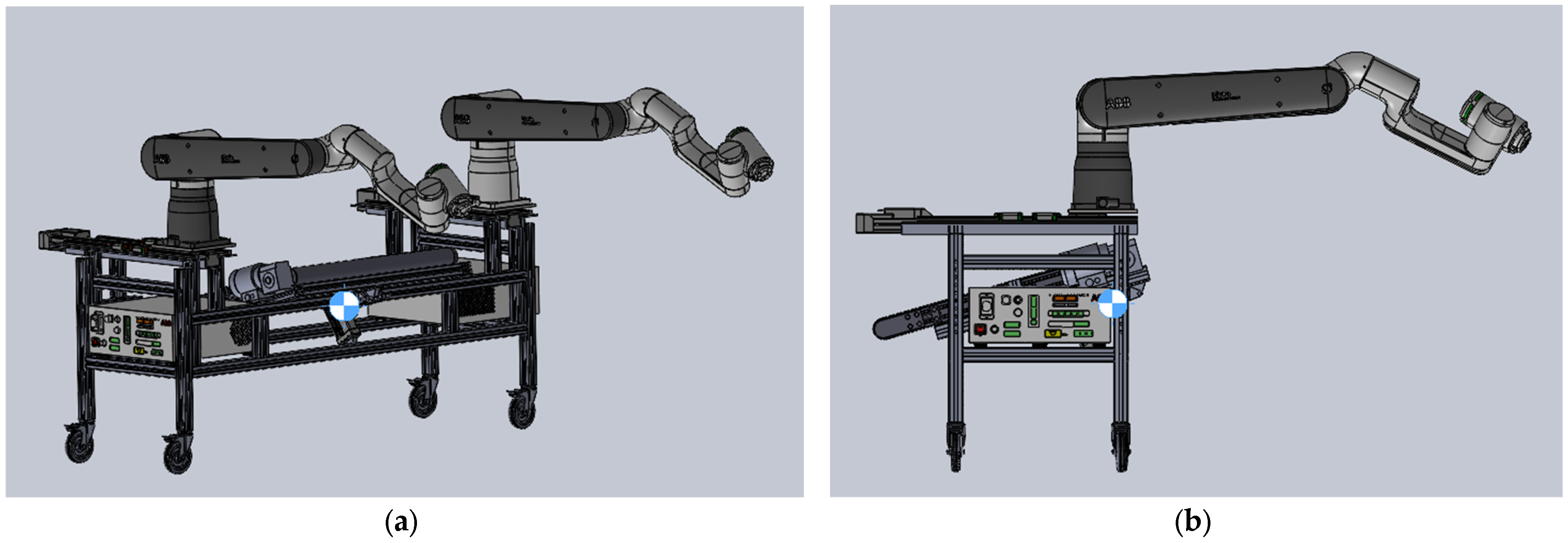
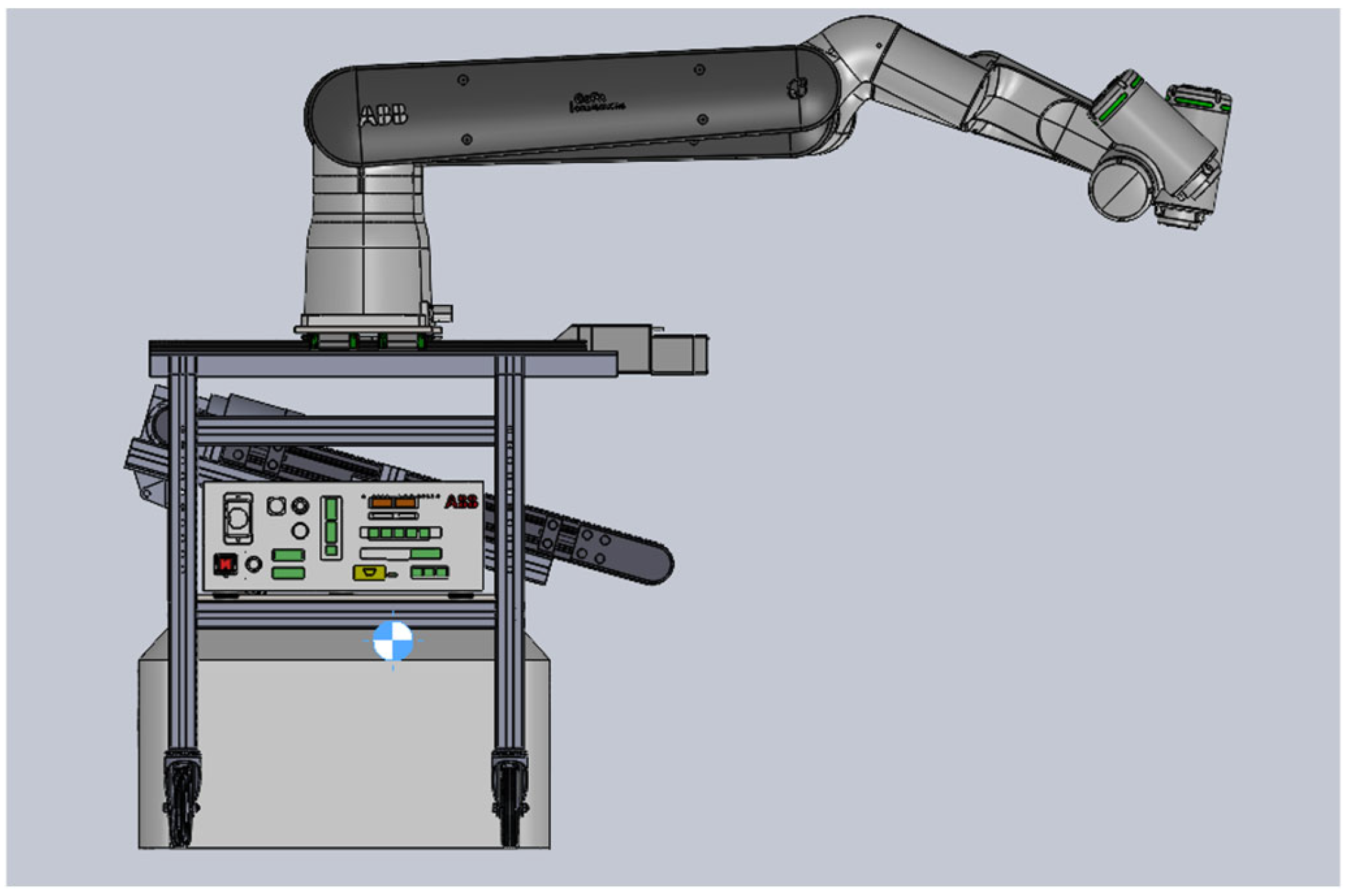
To complement the presentation of the final platform design, additional diagrams have been included to illustrate both the overall reach of the manipulators and the interaction of the platform with the airport trolley (Figure 16a,b).
Figure 17 shows the fully assembled MANiBOT prototype. This laboratory-ready platform integrates all structural and functional components—dual GoFa 12 manipulators, tilting conveyor, reinforced steel frame, and technical compartment—mounted on the AMR base. The image provides a direct view of the final system, bridging the iterative design process with the physical prototype now prepared for experimental validation.
In parallel, a summary table has been added to explicitly relate the functional requirements defined in Section 3 with the design features implemented throughout the iterative development process. For each requirement, the table indicates whether and how it is fulfilled in the final configuration of the MANiBOT platform. This structured analysis provides a direct link between the original project objectives and the mechanical decisions adopted, demonstrating that the resulting system not only meets but, in several cases, exceeds the operational demands identified in real-world scenarios. For clarity and readability, Table 2 presents two representative requirements as illustrative examples of the proposed design methodology. The complete and detailed version of this table, including all functional and design requirements, is provided in Appendix A.2 (Table A2).

6. Validation and Iterative Refinement: Description of the Evaluation Tests

To validate the structural robustness, stability, and safety of the MANiBOT platform, a comprehensive evaluation campaign was carried out. The tests were designed to replicate representative operational conditions while focusing exclusively on structural behavior, fastening reliability, and overall integrity of the system. Table 3 summarizes how the main design requirements were addressed through these tests, providing the rationale behind their selection. For clarity and readability, Table 3 presents a reduced set of validated design requirements. The complete validation matrix is included in Appendix A.3 (Table A3). The following subsections then describe in detail the procedures and methodologies employed.

6.1. Static Load Tests

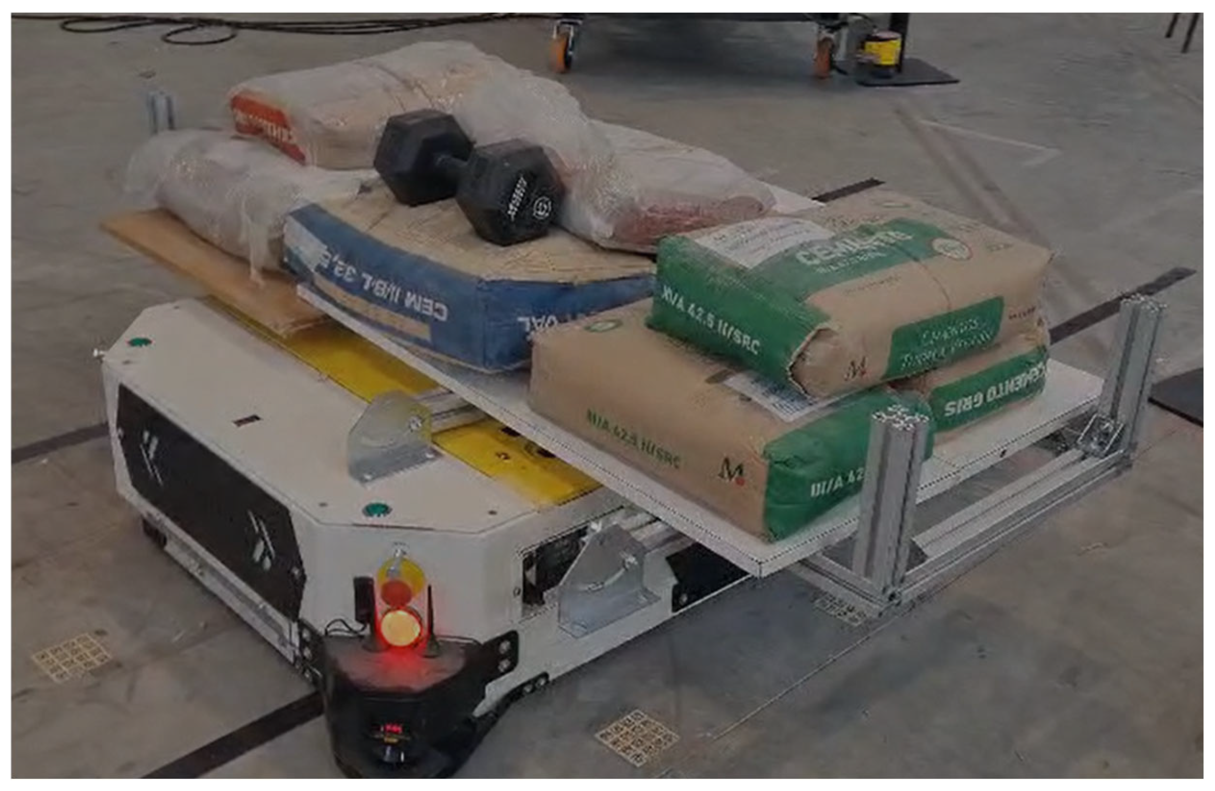
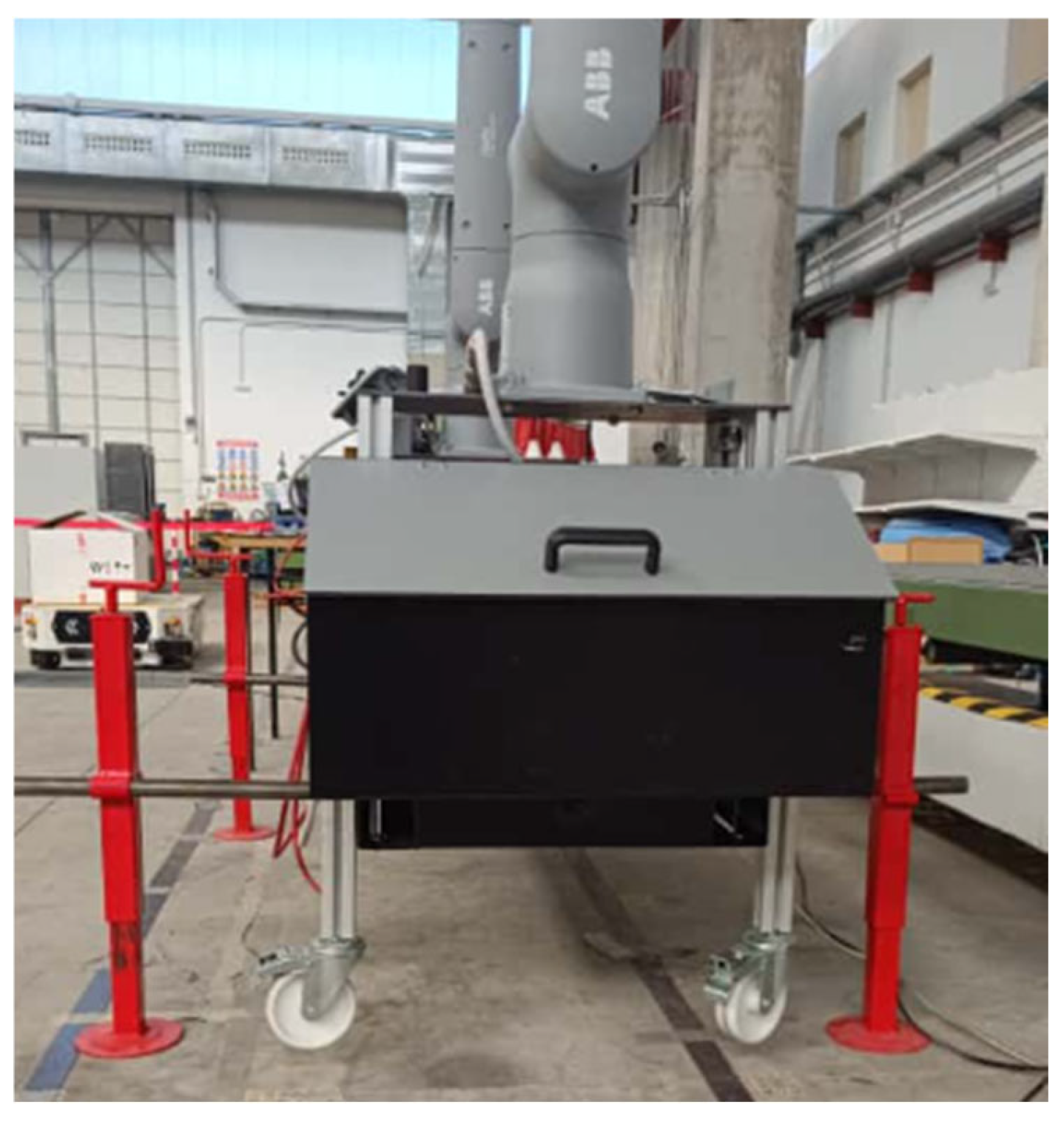
A series of static tests was performed to assess the platform’s ability to sustain the maximum expected operational load of 250 kg under both short- and long-term conditions. The evaluation was carried out with the platform resting on the ground and mounted on the AMR. In all cases, bolt torque was initially adjusted to 25 Nm and monitored using a calibrated torque wrench.
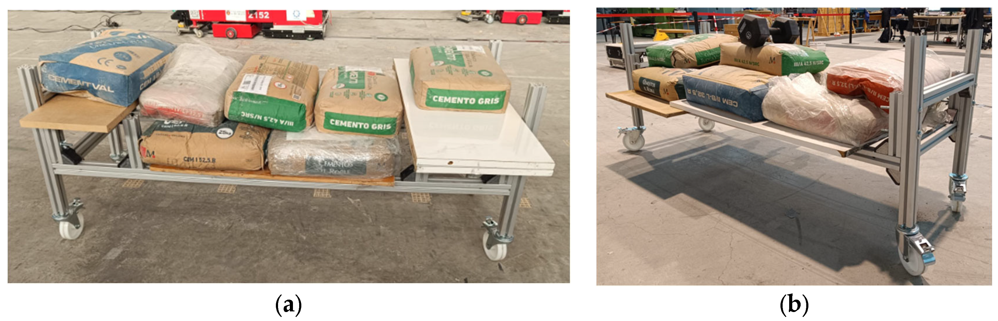
Static load on ground-supported structure (24 h and 20 days):
The objective was to confirm that the frame could withstand the full load without exceeding an allowable deformation of 0.5 mm or a torque variation greater than 1% (24 h) or 5% (20 days). Weights were uniformly distributed across the structure (Figure 18a,b).
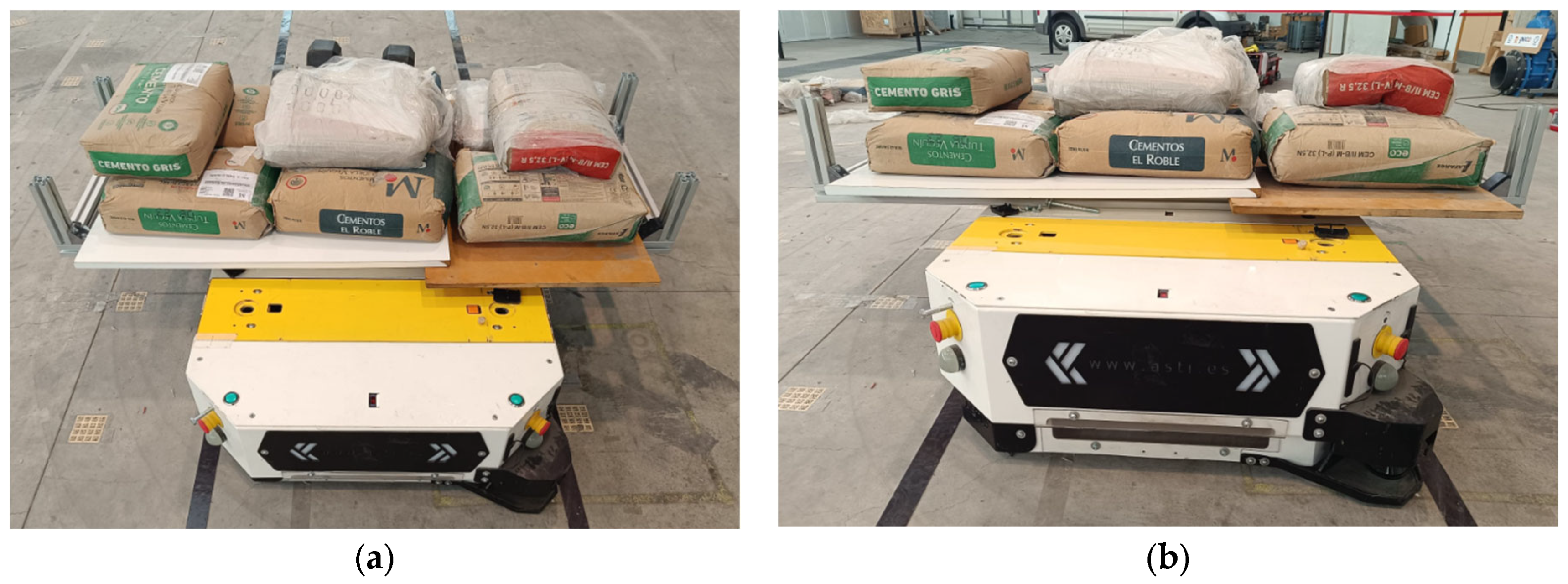
Static load on AMR-supported structure (24 h and 20 days):
The same procedure was repeated with the platform mounted directly on the AMR, removing ground supports. Acceptance criteria were identical: ≤0.5 mm deformation and torque variations below 1% (24 h) and 5% (20 days) (Figure 19a,b).

6.2. Dynamic Load Tests

Dynamic evaluations reproduced representative operating conditions in which the platform is subjected to cyclic accelerations while supporting the maximum operational load of 250 kg. In all cases, bolts were preloaded to 25 Nm and monitored with a calibrated torque wrench. The acceptance criterion was defined as a maximum torque variation ≤ 5%, together with the absence of permanent structural deformations.
Ground-supported dynamic test (V1):
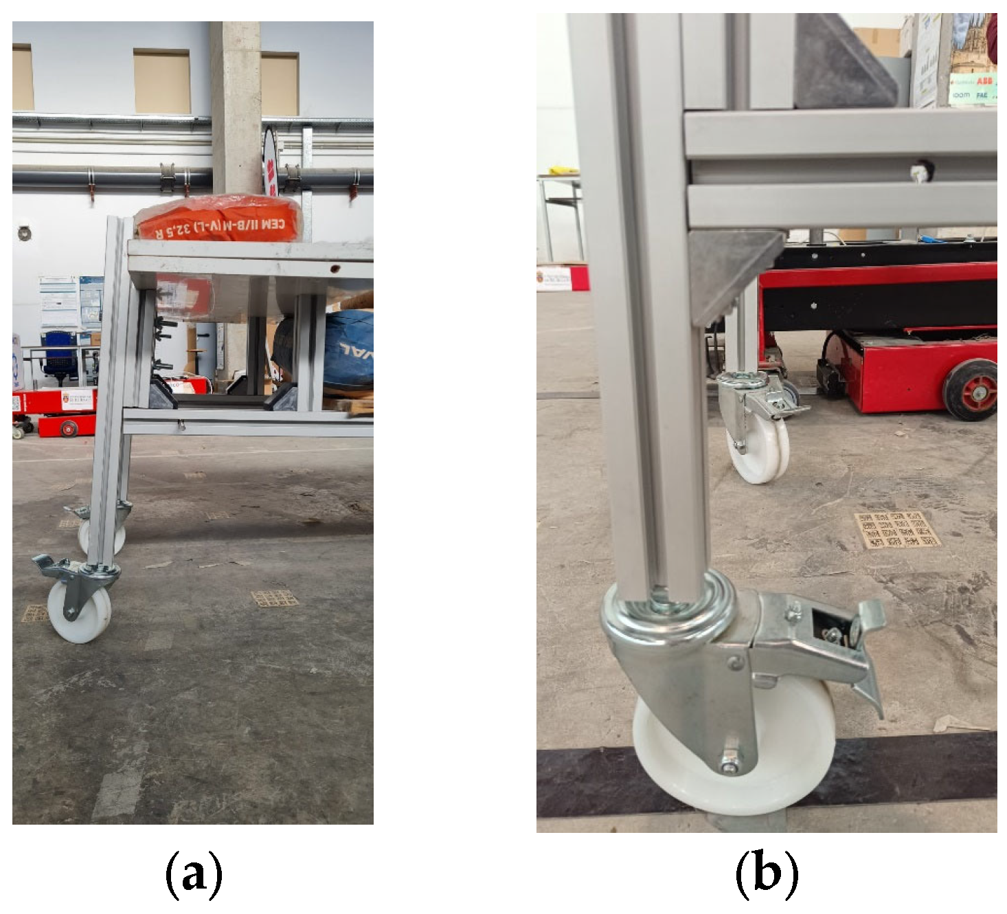
The baseline configuration of the platform was placed on its support legs and subjected to 10 forward and backward cycles over a 10 m track. This first test aimed to detect potential weaknesses in the structural joints (Figure 20a).
Ground-supported dynamic test (V2, reinforced):
Following observations of deformation in V1, reinforcement brackets were added at the junctions between longitudinal beams and support legs. The test was then repeated under the same loading and motion conditions to validate the effectiveness of the reinforcement (Figure 20b).
AMR-supported dynamic test:
The platform was mounted directly on the AMR, with ground supports removed, and subjected to 10 forward and backward cycles over a 5 m track. Bolt torque was measured before and after to assess fastener integrity under mobile dynamic stresses (Figure 21).

6.3. Deflection Tests

The deformation of the structure under maximum static load was quantified using dial gauges. The acceptance criterion was defined as a maximum allowable deflection of L / 250 .
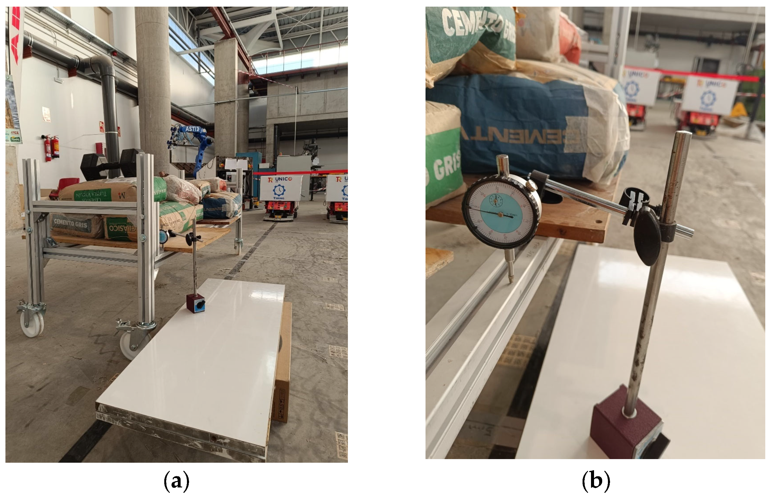
Distributed load deflection: With a total load of 250 kg uniformly distributed across the platform, deflection was measured between the central point and the lateral support points using a dial gauge (Figure 22a,b).
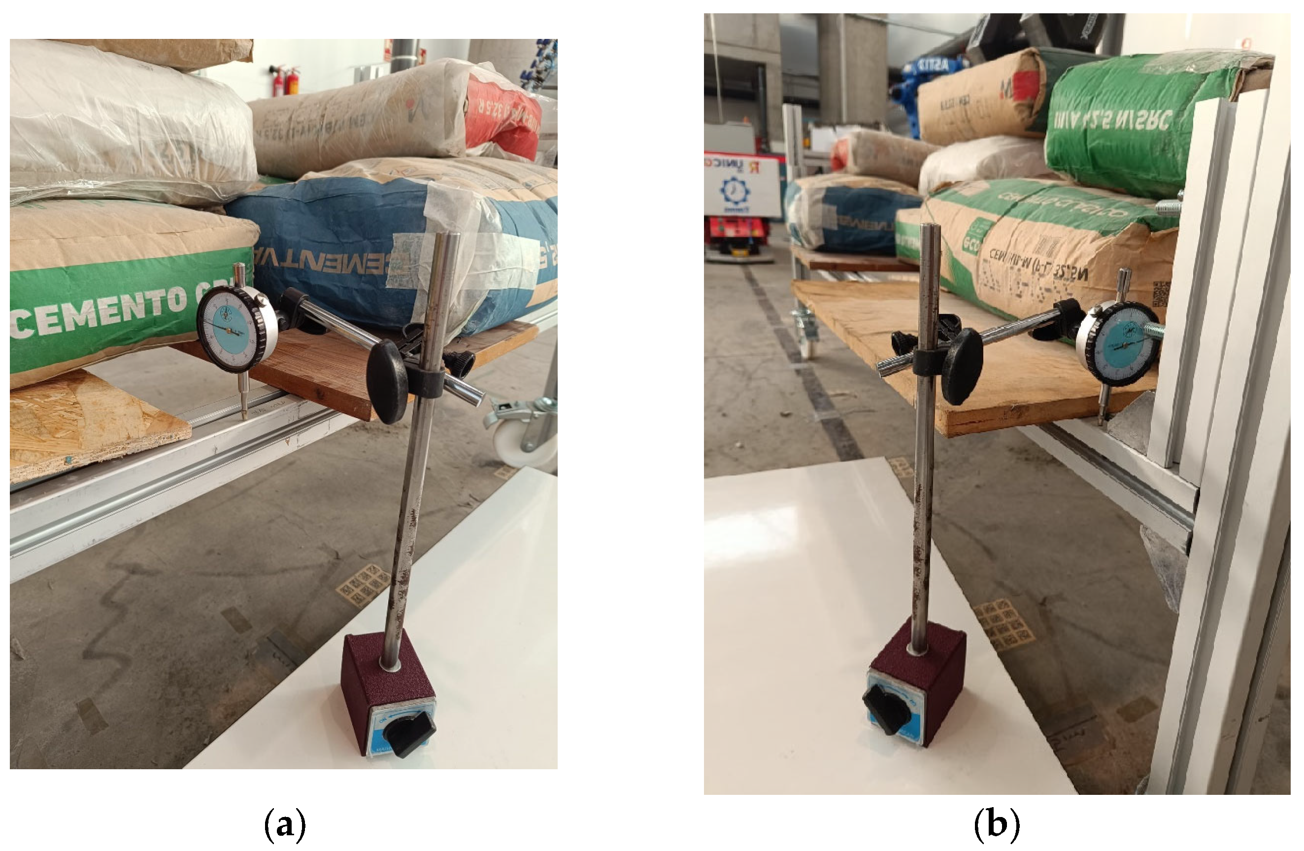
Central point load deflection: A second configuration added an additional 90 kg concentrated load at the midpoint of the frame, while maintaining the distributed 250 kg load. Deflection was again measured between central and lateral points to assess the system under more critical loading (Figure 23a,b).
Although these deflection tests were carried out on versions 10 and 11 of the platforms, which were built with aluminum profiles, the results are considered directly transferable to the final design. The definitive steel structure employs square hollow sections of greater thickness and a material with a significantly higher yield strength, providing more than four times the bending stiffness of the earlier aluminum profiles. This combined increase in sectional inertia and material strength ensures that the final platform exhibits superior resistance to deformation under load, thereby reinforcing the validity of the conclusions drawn from the aluminum prototypes.

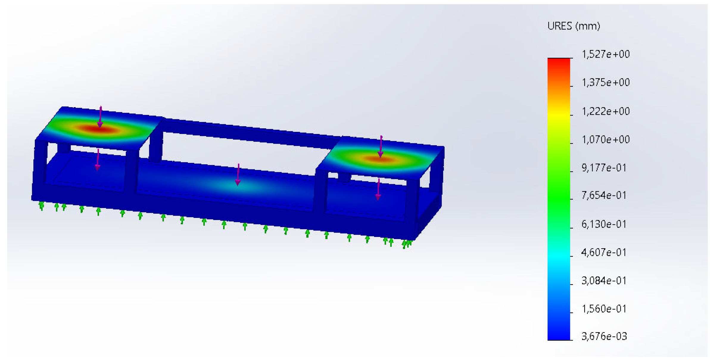
6.4. Finite Element Analysis of the Final Chassis

In addition to the experimental tests performed on the aluminum-based prototypes, a finite element analysis (FEA) was conducted to evaluate the structural behavior of the final steel chassis under representative loading conditions. The objective of this numerical study was not to replace experimental validation, but to complement it by providing a systematic and repeatable assessment of the platform response under different load distributions.

6.4.1. Load Application and Modeling Assumptions

The numerical model was derived directly from the final CAD geometry of the chassis, while assuming idealized connections, i.e., all joints were modeled as perfectly bonded. To ensure numerical robustness and to avoid non-physical local stress concentrations, the load application was intentionally simplified by consolidating it into a reduced set of representative regions associated with the dominant mass contributions of the system. These regions were conservatively sized, slightly overestimating the effective load transfer areas and thereby providing a robust and safe-side representation of the structural loading.
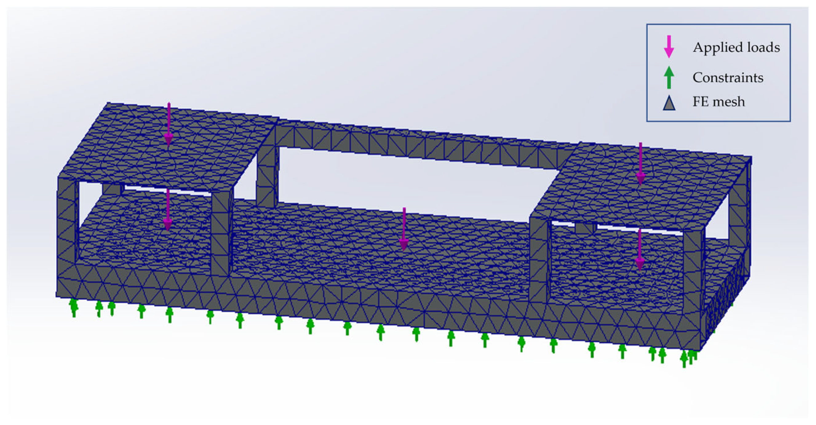
As illustrated in Figure 24, three main load application zones were considered:
  • Robot mounting areas (left and right): representing the weight transmitted by each robotic arm to the platform.
  • Central load area: representing the conveyor belt assembly and its payload.
  • Controller compartments: included in the load distribution to account for auxiliary equipment mass.
All loads were applied as vertical forces normal to the corresponding surfaces, ensuring a stable and physically consistent load introduction.

6.4.2. Parametric Load Definition

A systematic parametric study was carried out by varying both the magnitude and distribution of the applied loads:
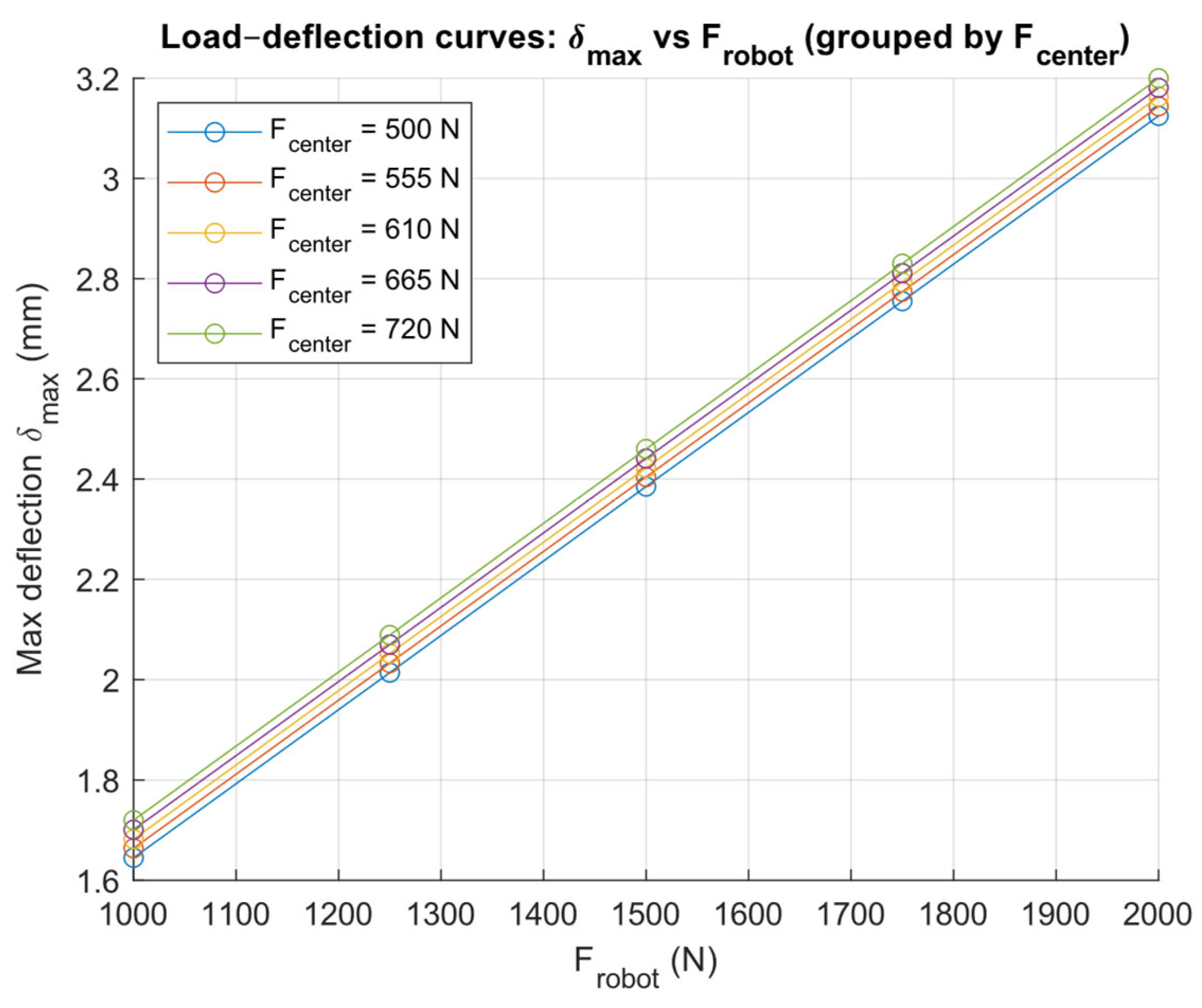
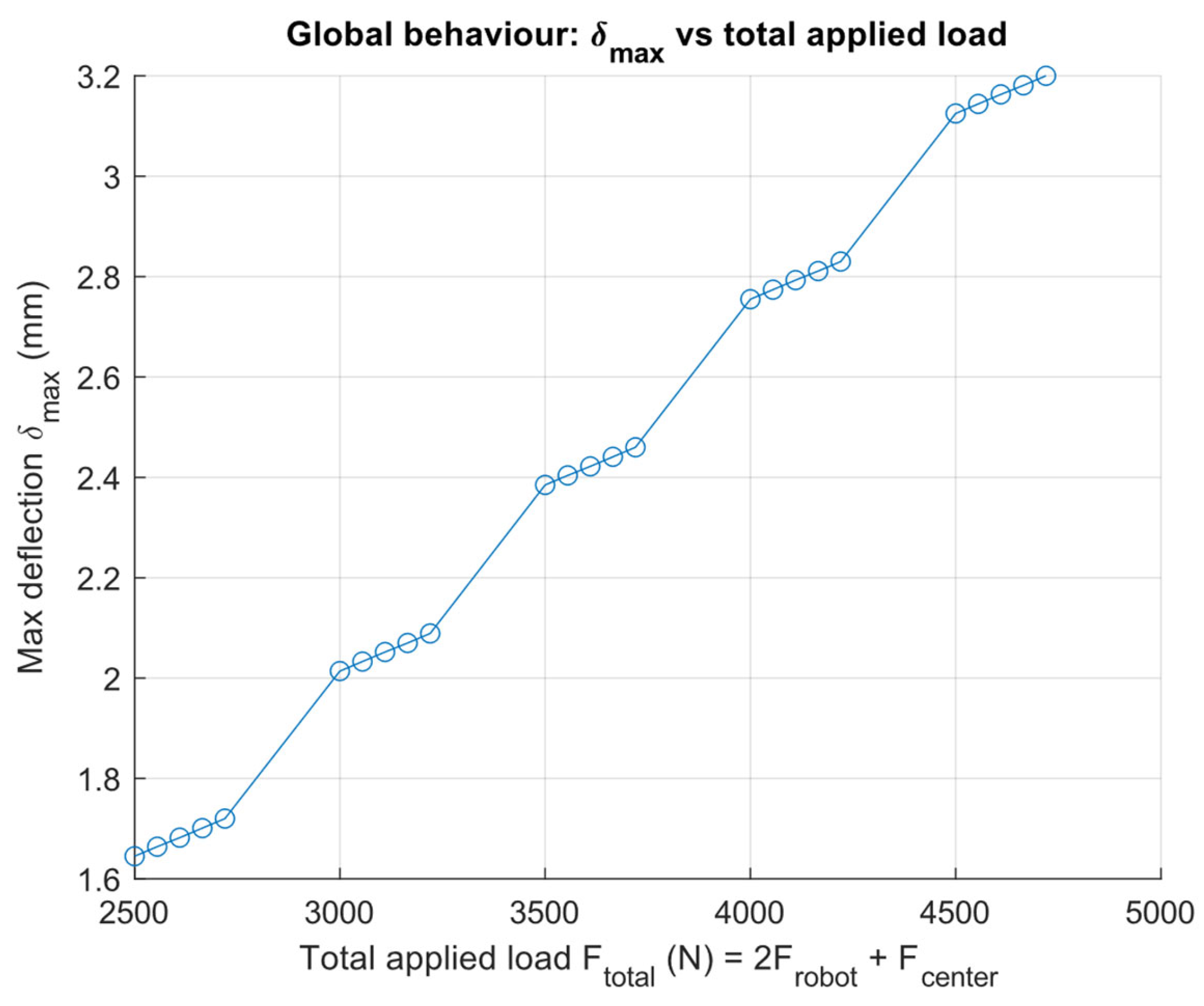
  • Robot loads: each robot mounting point was subjected to a vertical load ranging from 1000 N to 2000 N, applied independently at both the left and right robot locations.
  • Central load: the central region was loaded from 500 N, corresponding to the nominal weight of the conveyor belt, up to 720 N, representing the combined weight of the conveyor belt and a maximum payload (luggage) placed on top.
This load definition enabled the evaluation of multiple representative operating scenarios, covering both nominal and worst-case conditions, while maintaining a consistent modeling framework.

6.4.3. Boundary Conditions

The chassis was constrained at the lower support regions to replicate the contact conditions with the AMR. Vertical displacements were restricted at these locations, while allowing in-plane degrees of freedom to avoid artificial over-constraining of the structure.

6.4.4. Mesh Characteristics

A solid finite element mesh was employed for the analysis. Mesh generation was based on curvature refinement to adequately capture geometric details while preserving computational efficiency. Quadratic high-order solid elements were used throughout the model.
The main mesh characteristics are summarized below:
  • Element type: Quadratic solid elements (high order)
  • Meshing strategy: Curvature-based combined mesh
  • Maximum element size: approximately 52 mm
  • Minimum element size: approximately 52 mm
  • Total number of nodes: approximately 18,700
  • Total number of elements: approximately 9500
This mesh configuration was selected as a compromise between accuracy and computational cost, and it was found to be adequate for capturing the global deformation and stress patterns of the structure.

6.4.5. Scope of the Numerical Analysis

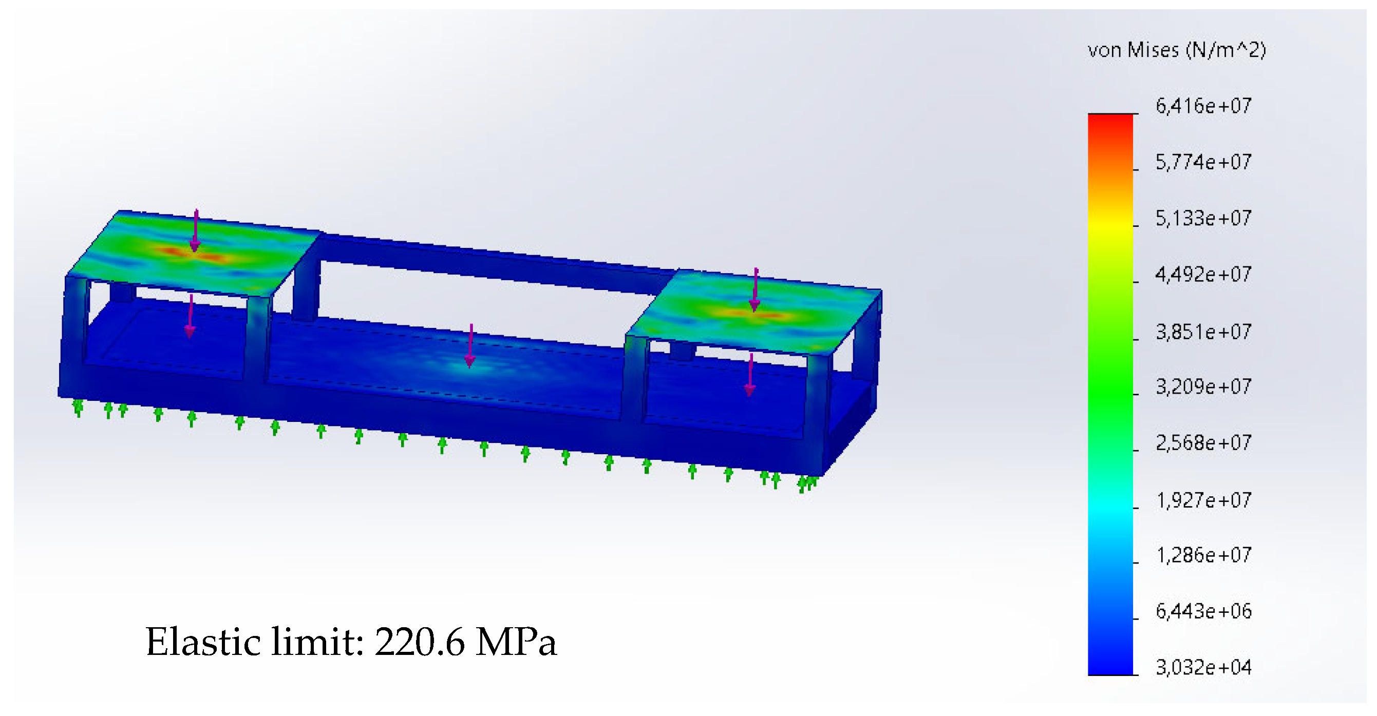
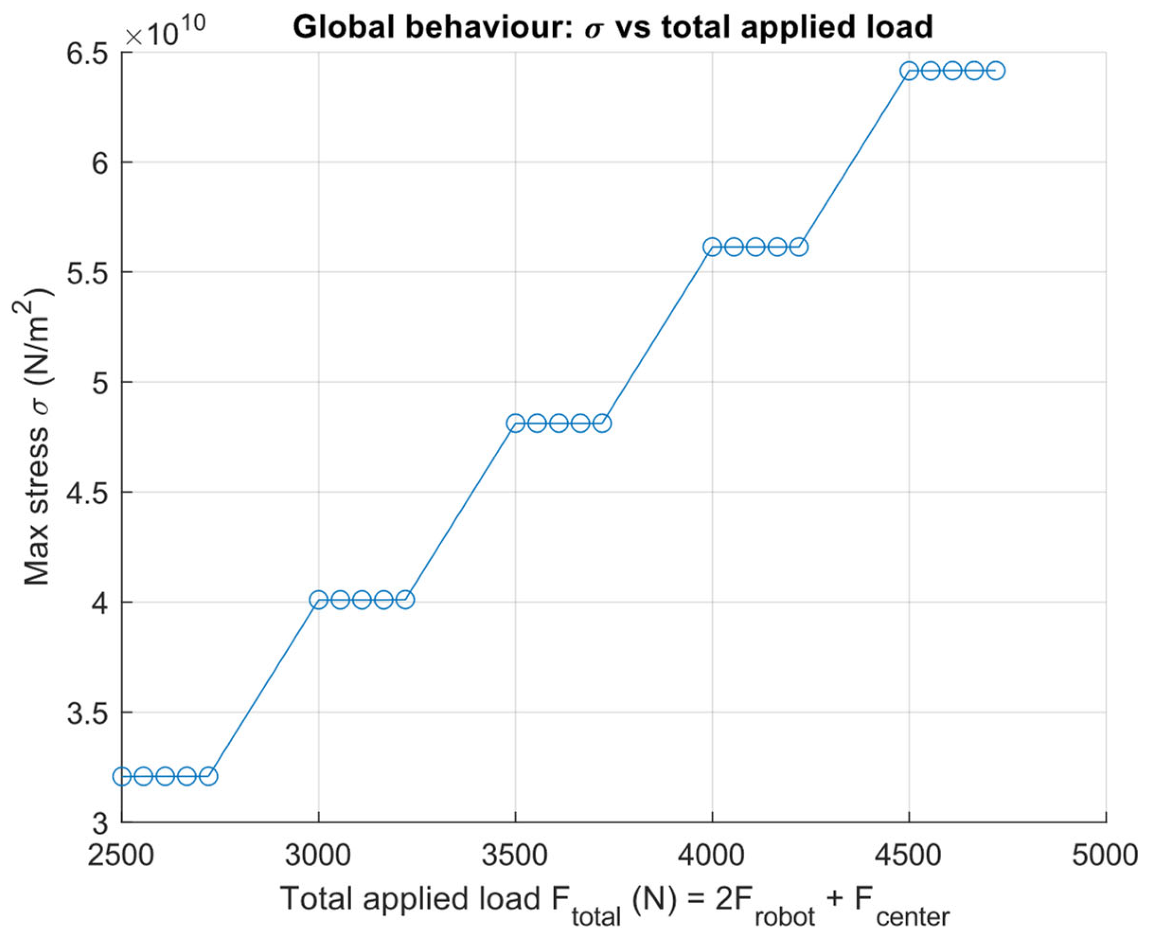
The FEA focused on extracting global deflection and maximum von Mises stress values for each load configuration. These outputs were later used to construct load–deflection and stress–load curves, which are presented and discussed in Section 7. The analysis was restricted to linear elastic behavior, as all evaluated scenarios remained well below the material yield limit.

6.5. Material Yielding Analysis

In addition to the experimental deflection measurements, complementary analytical calculations were performed to assess whether the structure could experience plastic deformation under maximum operational loading. The objective was to compare the stresses induced by representative load cases with the elastic limit of the structural steel, applying a safety factor of 1.5.
For the specific use cases addressed in this work, the robotic manipulators operate at low velocities and perform manipulation actions that are relatively infrequent and quasi-static in nature. Consequently, inertial forces associated with rapid accelerations or decelerations of the robot arms were considered negligible with respect to the dominant gravitational and payload-induced loads, and the material yielding analysis was therefore conducted under conservative static loading assumptions.
It should be noted, however, that for applications involving faster motions, high cycle frequencies, or highly dynamic manipulation, inertial effects may significantly increase the stresses transmitted to the supporting structure. In such scenarios, a more detailed dynamic-aware design methodology should be adopted.
To this aim, the following procedure could be used. First, the worst-case manipulation trajectory is identified, in terms of joint motion and payload handling, using a robot simulation environment. From this trajectory, the maximum joint accelerations and tool-center-point (TCP) accelerations are extracted. If the simulation tool provides interaction forces or reaction loads at the robot base, these can be directly used. Otherwise, inertial forces can be conservatively estimated by modeling the payload and relevant link masses as concentrated masses subjected to the computed accelerations. The resulting equivalent inertial forces and moments can then be applied to the supporting structure as external loads, either within a finite element model or through analytical stress evaluation. This approach allows dynamic effects to be incorporated in a conservative manner, ensuring that the supporting structure remains within the elastic regime under combined gravitational, payload, and inertial loading conditions.
The maximum induced stresses were calculated for the two representative cases in Equations (7)–(9).
I = ( b h 3 ( b 2 t ) ( h 2 t ) 3 ) 12
With b ,   h ,   t are width, height, and thickness, respectively.
y m a x = h 2
Finally, induced stress is calculated:
σ = M y m a x I
where M corresponds to the bending moment, y m a x to the maximum distance from the neutral axis and I to the moment of inertia.
To test yielding, the calculated stresses were compared with the material’s elastic limit ( σ e l a s t i c ) of 275 MPa. The structure remains in the elastic range if σ e l a s t i c < σ p l a s t i c .
If σ e l a s t i c > σ p l a s t i c , the structure may enter plastic deformation, leading to increased deflection over time.

6.6. Lifting System Evaluation

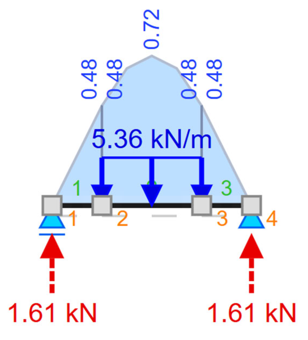
The lifting mechanism, designed to enable safe detachment and transfer of the platform between different AMR bases, was evaluated analytically and experimentally.
First of all, a conservative lifted mass ( m l i f t ) is considered, including a safety factor S F = 1.5 (Equation (10)), and lifted force ( F l i f t ) is calculated (Equation (11)).
m l i f t = m s t r u c t u r e · S F
F l i f t = m l i f t · g
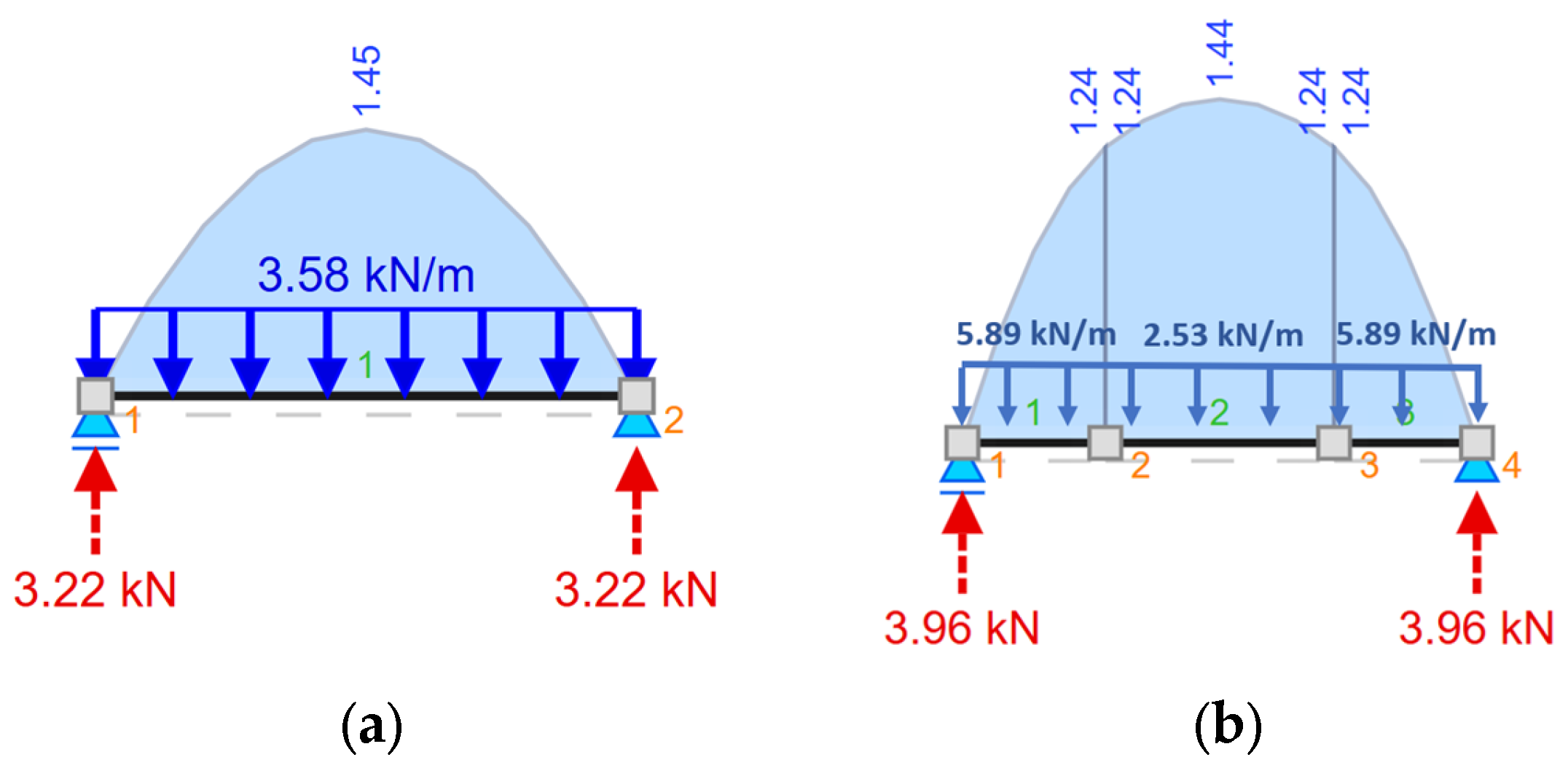
The load is applied over a span L (lifting bar clear distance). Treating the load as uniformly distributed as shown in Equation (4)
ω = F l i f t L
Because the platform is lifted by four supports, the load per side is halved:
ω b a r = ω 2
Now, using the maximum bending moment, M m a x , the minimum solid circular bar is calculated (Equations (9)–(11)).
I = π 4 4 64
c = d 2
σ m a x = M m a x c I = 32 M m a x π d 3
To test the acceptance criteria, the calculated stresses were compared with the material’s elastic limit ( σ e l a s t i c ) of 316 MPa. The structure may remain in the elastic range if σ m a x < σ p l a s t i c to accept the proposed bar diameter.

6.7. Rollover Stability Tests

To ensure safe operation, rollover stability tests were conducted to evaluate whether the platform’s center of gravity (CoG) remains within the support polygon under the most unfavorable manipulator configurations. This analysis was performed on version 10 of the platform, both with and without the AMR attached.
Although dynamic effects were not explicitly modeled through time-dependent equations of motion, inertial effects associated with manipulator operation were conservatively taken into account by considering the maximum torques that the robotic arms can exert in their most unfavorable configurations.
Specifically, these torques were modeled in the CAD environment by applying equivalent concentrated masses at representative distances from the platform reference frame, reproducing the worst-case bending moments transmitted by the manipulators to the structure. This conservative static equivalence allows the center of gravity (CoG) to be evaluated under the most unfavorable manipulator configurations.
The acceptance criterion required the projection of the CoG to remain within the polygon defined by the platform’s supporting legs. These rollover stability tests were conducted under two different conditions: with and without the AMR attached to the platform.
If stability could not be guaranteed, anti-rollover measures would be explored and tested.

6.8. Summary

To consolidate the description of the evaluation campaign, Table 4 provides a structured overview of all tests performed on the MANiBOT platform. A detailed description of all tests and conditions can be found in Appendix A.4 (Table A4). For each test, the table specifies its main objective, the methodology and instruments applied, and the corresponding figure where the setup is documented. This summary highlights the systematic nature of the validation process, covering static and dynamic load assessments, deflection measurements, material yielding analysis, lifting system verification, and rollover evaluations. Beyond serving as a compact reference, the table establishes the methodological link between the detailed procedures described above and the presentation of results in Section 7.

7. Results

The testing campaign provided a comprehensive evaluation of the MANiBOT platform under static, dynamic, and stability conditions. The following subsections summarize the outcomes of each test, highlighting the extent to which the structural design met the acceptance criteria established in Section 6.

7.1. Static Load Tests

The platform demonstrated robust performance under all static load conditions. No permanent deformations were detected, and torque variations remained well below the acceptance thresholds (Table 5).
These results confirm that the platform maintains its structural integrity and fastening reliability both on the ground and on the AMR, for both short- and long-term operation. As a preventive measure, periodic bolt retightening every three months is recommended to guarantee long-term reliability.

7.2. Dynamic Load Tests

Dynamic evaluations revealed important insights into the platform’s performance under cyclic stresses. The results obtained from these tests are presented in Table 6.
These results show that the initial structure (V1) exhibited critical weaknesses under cyclic loads, with visible deformation at the beam–leg junctions. The reinforced version (V2) effectively solved this issue, eliminating structural deformation. However, slight loosening of four bolts suggests the need for preventive retightening after transport. When mounted on the AMR, the platform demonstrated robust stability and fastening reliability, validating its suitability for mobile dynamic operations.

7.3. Deflection Tests

The results confirm that structural deflections remained below the allowable limit of 7.2 mm in both loading configurations, demonstrating that the platform operates within the elastic range and maintains its structural integrity under maximum static loading (Table 7).

7.4. Material Yielding Analysis

The analytical verification confirmed that the steel structure remains well within the elastic range under the most demanding loading scenarios. Using the properties of the 80 × 80 × 3 mm (b, h, and t, respectively), square hollow section ( I = 4.62 × 10 6   m m 4 ,   y m a x = 40   m m ) and considering a safety factor of 1.5, two possible loading configurations were considered (Figure 25a,b).
  • Case 1—Distributed structural mass: The total lifted mass of 437.5 kg was increased by a safety factor to 656.25 kg. When distributed over the full 1.8 m span, this corresponded to a line load of 364.6 kg/m (≈3.58 kN/m). The resulting maximum bending moment was calculated as M m a x , 1 = 1450   N m .
  • Case 2—Combined lateral and central loading: Two lateral loads of 200 kg were considered, increased to 300 kg after applying the safety factor, corresponding to a distributed load of 600 kg/m (≈5.89 kN/m). In addition, a central mass of 137.5 kg was increased to 206.25 kg. This combined configuration produced a maximum bending moment of M m a x , 1 = 1440   N m .
Since Case 1 generates the highest bending moment, it was adopted as the design reference for structural verification. Results are presented in Table 8.
Both cases demonstrate a large safety margin, with induced stresses more than one order of magnitude below the elastic limit of S275 steel (275 MPa). Case 2, representing the most unfavorable load configuration, reached only 12.1 MPa, confirming that no yielding or progressive plastic deformation is expected. These results validate the robustness of the selected structural section under real operational conditions.

7.5. Finite Element Analysis of the Final Chassis

The finite element analysis provided a complementary numerical assessment of the structural behavior of the final steel chassis under a wide range of representative loading conditions.
Figure 26 shows the von Mises stress distribution obtained for a representative worst-case loading configuration. As expected, the highest stress concentrations appear at the robot mounting regions, where the applied loads are directly transferred to the structural frame. Lower stress levels are observed along the longitudinal beams and at the central section of the chassis. In all evaluated scenarios, the maximum von Mises stress remains significantly below the elastic limit of the structural steel, confirming that the structure operates entirely within the linear elastic regime.
Figure 27 presents the corresponding resultant displacement (URES) field for the same loading condition. The maximum deflection occurs at the robot mounting platforms, while the central region exhibits a smoother deformation profile. This deformation pattern is consistent with the experimental deflection tests, where the largest displacements were measured near the most heavily loaded areas. The absolute displacement levels remain low and compatible with the acceptance criteria defined in Section 6.3 (≤7.2 mm).
To provide a clearer and more quantitative interpretation, the numerical results were post-processed to generate load–response curves. Figure 28 illustrates the evolution of maximum von Mises stress as a function of the total applied load. A nearly linear relationship is observed, which is consistent with the assumption of linear elastic behavior and confirms the absence of non-linear effects or material yielding within the investigated load range.
Figure 29 presents the maximum deflection as a function of the robot load for different central load levels. The curves illustrate the influence of the suitcase weight applied at the central section of the platform, while the load applied on each side of the platform is varied from 1000 N to 2000 N. The results highlight how increasing the central load leads to higher global deflection for the same robot load, emphasizing the combined effect of robot weight and payload distribution on the structural response.
These results highlight that not only the magnitude but also the spatial distribution of the loads plays a significant role in the global structural response of the platform.
Finally, Figure 30 summarizes the global deformation behavior by representing the maximum deflection as a function of the total applied load for all evaluated scenarios.
Despite the different load distributions, the overall trend remains consistent, showing a stable and predictable increase in deflection with increasing load. This global view reinforces the robustness of the chassis design and confirms that the platform maintains adequate stiffness under all considered operating conditions.
Overall, the FEA results are in good agreement with the experimental findings and analytical calculations. The numerical analysis confirms that the final steel chassis exhibits sufficient stiffness and structural safety margins under representative operational loads, thereby supporting the validity of the adopted design.

7.6. Lifting System Evaluation

The lifting system was validated analytically and experimentally to ensure its capacity to safely elevate the platform during AMR exchange.
With the Analytical calculations, the aim was to determine the minimum diameter of the transverse steel bars capable of supporting the weight of the final structure (437.5 kg ≈ 4291.88 N). A safety factor of 1.5 was applied, and the material’s elastic limit was defined as 316 MPa. (Figure 31). The acceptance criterion required the induced stress to remain below the elastic limit for all scenarios.
Analytical calculations determined the minimum required diameter of the transverse lifting bar under the worst-case bending moment of M m a x = 720   N . Applying the stress criterion with the elastic limit of σ e l a s t i c = 316   M P a , the minimum diameter was obtained as d m i n = 28.5   m m .
In conclusion, the 30 mm transverse bar was selected as the standard, exceeding the minimum required values and ensuring operational safety. Among the tested configurations, the one-point support design provided the most favorable results, requiring the lowest stress capacity and thus offering the safest operational margin.
To confirm the analytical findings, a practical lifting test was conducted in which four lifting legs supported a total load of 437.5 kg (Figure 32). This experiment empirically demonstrated that the calculated bar neither deflects excessively nor fails under load, and that the lifting mechanism is both capable and sufficient to safely perform the platform elevation required for AMR exchange.

7.7. Rollover Stability Tests

The rollover analyses revealed critical stability limitations in platform version 10 when evaluated without the AMR:
Standalone configuration: The CoG (shown as the blue–white marker) was found to lie dangerously close to the support polygon, posing a tipping risk under unfavorable manipulator postures (Figure 33a,b).
With AMR: The additional weight shifted the CoG downward, fully eliminating the rollover risk (Figure 34).
To mitigate the instability observed in standalone mode, several corrective strategies were evaluated, including false AMR anchoring (Figure 35a), widened support legs (Figure 35b), and counterweight systems with steel or concrete masses (Figure 35c,d). Each alternative was experimentally validated in simulation to examine feasibility and operational impact (Table 9).

8. Conclusions

This paper has presented the methodological framework and its practical application to the design and realization of the MANiBOT dual-arm robotic platform. Rather than describing a single prototype in isolation, the contribution provides a generalizable design methodology that guides the development of bimanual robotic structures from requirement definition to experimental validation.
The process followed a requirement-driven and iterative design cycle, in which each stage—requirement identification, conceptual architecture, detailed mechanical design, prototype construction, and validation—generated traceable deliverables and decision criteria. The application of this workflow to the MANiBOT platform demonstrated its capacity to ensure structural robustness, modularity, and adaptability while maintaining compliance with safety and interoperability standards.
The methodological approach enabled the systematic transformation of functional and operational requirements—derived from supermarket and airport scenarios—into verified engineering solutions. Critical outcomes of the process include:
  • A validated requirement specification framework, translating operational tasks into measurable design constraints and performance indicators.
  • A conceptual architecture supporting dual-arm cooperation, workspace overlap, and modular reconfiguration for different environments.
  • A structurally optimized detailed design, using reinforced steel and standardized interfaces to balance rigidity, manufacturability, and maintainability.
  • A prototyping and validation stage confirming that analytical predictions and physical tests are consistent within the defined acceptance criteria.
Beyond the specific case of MANiBOT, the results confirm that the proposed methodology can serve as a replicable guideline for the development of future dual-arm robotic platforms. The integration of requirement traceability, simulation-based verification, and iterative refinement ensures reproducibility and design transparency—critical aspects for technology transfer and industrial adoption.
Future work will extend this methodology toward the electromechanical and cognitive integration of perception modules, tactile and proximity sensors, and high-level control frameworks. The upcoming trials in real supermarket and airport environments will further validate not only the mechanical design but also the platform’s capacity for perception-driven and human-aware manipulation.
In conclusion, the MANiBOT platform embodies both a proof of concept and a proof of methodology. By establishing a structured and verifiable workflow for designing dual-arm robotic systems, this work contributes a practical blueprint for developing next-generation collaborative platforms that combine mechanical robustness, safety compliance, and adaptive intelligence in dynamic, human-shared environments.

Author Contributions

M.P.-Y.: Conceptualization, Methodology, Software, Validation, Writing—Original Draft Preparation, Review and Editing. J.E.S.-G.: Conceptualization, Methodology, Formal Analysis, Supervision, Writing—Original Draft Preparation, Review and Editing. All authors have read and agreed to the published version of the manuscript.

Funding

This work was partially supported by the European Commission, under the European Project MANiBOT, grant number 101120823.

Data Availability Statement

The original contributions presented in this study are included in the article. Further inquiries can be directed to the corresponding authors.

Acknowledgments

The authors acknowledge the use of AI-based language tools to assist with English language polishing and stylistic improvements. The authors take full responsibility for the content of the manuscript.

Conflicts of Interest

The authors declare no conflict of interest.

Appendix A. Complete Tables

This appendix includes the complete versions of the tables summarized in the main body of the paper. It provides the full comparative analysis of dual-arm robotic platforms, the detailed design requirements considered during the iterative development of the MANiBOT platform, the requirements validated through structural testing, and the complete set of evaluation tests performed.

Appendix A.1

Table A1. Comparative analysis of dual-arm robotic platforms with respect to design methodology, mobility, and adaptability.
ReferencePlatform Design MethodologyArm ConfigurationMobility (AMR/Mobile Base)Robot-Agnostic (Adaptability)Main Focus
Peñacoba and Sierra-García (This work)Yes (generalized and structured). Proposes a five-stage framework spanning from requirements definition to experimental validation, applicable to different platforms.Dual-arm (bimanual)Yes. Mobility is considered from the early design stages.Yes. Framework applicable to different manipulators and AMRs.Standardization of mechanical engineering and structural validation of mobile dual-arm platforms.
Li et al. (2023) [21]No. Describes a hardware/software integration tailored to a specific application.Multi-arm (four Cartesian arms)Yes. Wheeled mobile platform (Ackermann).No. Application-specific design for agricultural harvesting.Task planning, perception, and efficient apple harvesting.
Park et al. (2014) [17]No. Relies on kinematic and dynamic analysis for an ad hoc design.Dual-arm (custom 7-DoF arms)Yes. Omnidirectional mobile platform.No. Custom-designed arms integrated into the torso.Electronic device assembly and workspace analysis.
Di Castro et al. (2017) [19]Partial. Presents a modular control architecture, but not a step-by-step mechanical design methodology.Dual-arm (configurable)Yes. CERNbot tracked/wheeled platform.Yes (modular hardware configuration).Control architecture for teleoperation and navigation in hazardous environments.
Chen and Hsiao (2023) [22]No. Focuses on the development and integration of joint modules.Dual-arm (14 DoF, proprietary modules)No. Stationary system cooperating with an external AMR.No. Based on proprietary all-in-one joint modules.Development of joint modules and control for collaborative industrial assembly.
Duan et al. (2023) [25]No. Proposes a six-dimensional Digital Twin architecture rather than a physical construction methodology.Dual-arm (UR5 + UR10)No. Fixed experimental setup.Partial (software-level framework).Visual monitoring and digital twin for assembly processes.
Moore et al. (2007) [18]No. Describes the implementation of a fixed workcell in an existing facility.Dual-arm (Stäubli arms)No. Large-scale fixed installation.No. Designed for a specific pharmaceutical screening application.Flexible programming and workflow management for high-throughput screening.

Appendix A.2

Table A2. Design requirements across the iterative development of the MANiBOT platform.
Requirement IDv1–3 (Conceptual)v4–6 (Functional Prototyping)v7–8 (Advanced Integration)v9–10 (Detailed Design)v11–12 (Final Structure)
FR1—Dual-arm capabilityConceptual positioning of manipulators is explored in a volumetric model.First integration of dual GoFa 5 arms with a placeholder conveyor.Upgrade to dual GoFa 12 arms with linear tracks to extend reach.Verified manipulator–conveyor coordination and motion overlap.Final dual GoFa 12 integration consolidated in reinforced frame.
FR2—Workspace overlapEarly assessment of arm reach envelopes.Preliminary evaluation of cooperative workspace in simulation.Linear-track architecture increased shared workspace coverage.Detailed CAD and kinematic verification of collision-free overlap.Experimental validation confirmed full overlap without interference.
FR3—Conveyor subsystem integrationConveyor not yet included.Placeholder conveyor introduced for feasibility checks.The linear conveyor prototype enabled coordinated manipulation.Inclinable conveyor implemented for multi-height unloading.Custom 1.8 m tilting conveyor integrated; repeatability validated.
FR4—Structural rigidity under payloadConceptual frame only, no load validation.Aluminum prototype built; reinforcements added after deflection tests.Sheet-metal alternative studied to improve stiffness.Transition to extruded-aluminum profiles; FEA confirmed deflection within limits.Reinforced 80 mm steel profiles validated under static/dynamic loading; CoG lowered.
FR5—Stability on AMR baseBasic stability analysis conceptually reviewed.Anchor reinforcements improved static equilibrium.Linear-track kinematics assessed for dynamic stability.Rollover analyses identified risks; counterweights tested.Steel reinforcement and low-mounted mass ensured stable behaviour on AMRs.
FR6—Modularity and maintainabilityInternal distribution not defined.Preliminary ventilation and access panels designed.Compartments reorganized to improve accessibility.Modular aluminum profiles are adopted for easy subsystem replacement.Final steel frame with removable panels and standardized cable routing.
FR7—Allocation of internal componentsOnly external volume estimated.First internal layout trials for electronics and power supply.Compartments reorganized; clearer electronics allocation.Conveyor and electronics integration refined; sensors included.Lower technical compartment defined for NUCs, Jetsons, PSUs, and controllers.
FR8—Symmetry and balanceA symmetrical layout is proposed for control simplicity.Partial geometric symmetry was achieved in prototypes.Bilateral configuration completed with mirrored supports.Structural reinforcements preserved geometric symmetry.Final mirrored layout validated; balanced torque distribution confirmed.
OR1—Spatial validation and AMR adaptabilityVolumetric envelope defined on P204 AMR base.A detachable upper module was introduced for modular mounting.Linear-track layout is considered to expand the workspace.Structural redesign to accommodate airport trolley; conveyor tilt added.Standardized AMR interface confirmed for P204/P604 bases.
OR2—Working height and task rangeNot yet defined.Conveyor height is conceptually positioned for accessibility.Linear motion extended manipulation range.Tilting conveyor enabled operation between 0.5 and 2.5 m.Final design achieved full vertical reach, validated experimentally.
OR3—Safety and regulatory complianceSafety distances are qualitatively considered.Preliminary HRI clearances applied.Layout aligned with ISO 10218-2 workspace rules.Safety components (E-Stop, force limiters) integrated.Compliance with ISO/TS 15066 confirmed through tests.
OR4—Maintainability and service accessNot addressed.Early consideration of ventilation and serviceability.Panels reorganized for accessibility.Cable routing and ventilation paths are defined.Service access optimized; MTTR reduced below specification.
OR5—Power and computing integrationInternal electronics not yet planned.Space reserved for power distribution.First integration of computing devices in a mock-up.Dedicated areas for controllers and communication units.The lower compartment hosts power and computing hardware with EMC compliance.
DR1—Spatial validation and AMR adaptabilityYes—volumetric envelope defined on P204 AMR; generic geometry adaptable.Yes—detachable upper module introduced for modular mounting on multiple AMRs.Yes—linear tracks considered with GoFa 12, ensuring coverage of extended workspaces.Yes—structural redesign to adapt to Fraport luggage cart; conveyor tilting implemented.Yes—standardized 80 mm steel profiles and universal AMR mounting interfaces.
DR2—Manipulator integrationNo—only conceptual positioning studied.Partial—first integration of dual GoFa 5 arms and placeholder conveyor.Yes—upgrade to GoFa 12 arms with linear axes, validated for higher payload and reach.Yes—manipulator–conveyor coordination verified under multi-level loading scenarios.Yes—final dual GoFa 12 integration consolidated in reinforced frame.
DR3—Conveyor integration and evolutionNo—conveyor not yet included.Partial—placeholder conveyor introduced to simulate transfer.Yes—linear motion enabled cooperative use of the conveyor.Yes—inclinable conveyor implemented for airport cart loading.Yes—custom conveyor (1.8 m width) integrated for large luggage handling.
DR4—Structural robustness and load capacityNo—conceptual frame only, no load validation.Partial—aluminum prototypes tested; reinforcements added after dynamic deformation.Partial—sheet-metal exploration; improved rigidity, but not a final solution.Yes—extruded aluminum profiles adopted; deflection tests confirmed acceptable limits.Yes—reinforced steel frame validated under static/dynamic tests; center of gravity lowered.
DR5—Maintainability and modularityNo—internal distribution not defined.Partial—initial ventilation and panel layouts explored.Partial—compartments reorganized for improved access.Yes—modular aluminum profiles allowed flexible integration of subsystems.Yes—a lower technical compartment introduced for safe, accessible housing of electronics.
DR6—Stability and rollover preventionNo—only conceptual considerations of stability.Partial—anchor reinforcements improved static stability.Partial—linear track analysis ensured a workspace without collisions.Partial—rollover analyses identified risk; countermeasure strategies tested.Yes—steel reinforcement, counterweight systems, and lower center of gravity ensured robust stability.
DR7—Allocation and definition of internal componentsNo—only external volume estimated, internal layout undefined.Partial—first distribution trials: preliminary space for panels, power supply, and ventilation.Partial—compartments reorganized, internal electronics more clearly arranged.Yes—conveyor and electronics integration refined; space for controllers and sensors accounted for.Yes—dedicated lower compartment defined for NUCs, Jetsons, PSU, and communication units, with protected access and organized cabling.

Appendix A.3

Table A3. Design requirements validated through structural tests.
Design Requirement (DR)Related TestsPurpose of the Tests
DR4—Structural robustness and load capacityStatic load tests (1–4); Deflection tests (8–9); Finite Element Analysis tests (10); Material yielding analysis (11). Confirm the platform’s ability to sustain the maximum operational load (250 kg) over short and long durations, ensuring that deflection remains within elastic limits and that no yielding occurs.
DR1—Spatial validation and AMR adaptabilityStatic load on AMR-supported structure (3–4); Dynamic AMR-supported test (7)Validate that the structure remains stable and reliable when mounted on different AMRs, replicating real deployment conditions.
DR5—Maintainability and modularityLifting system analysis and validation (11–12)Ensure the feasibility of safely lifting and transferring the platform between AMRs, verifying both analytical sizing and experimental performance of the lifting system.
DR6—Stability and rollover preventionRollover analysis (13); Anti-rollover solutions (14–18)Assess tipping risk with the platform alone or mounted on the AMR, and evaluate corrective measures such as widened legs or counterweights to guarantee operational safety.

Appendix A.4

Table A4. Summary of evaluation tests performed on the MANiBOT platform.
Test No.Test NameObjectiveMethodology/ToolsFigure(s)
1Static load (ground-supported, 24 h)Validate structural capacity under nominal load (250 kg) over a short durationDistributed load; torque wrench monitoringFigure 18a
2Static load (ground-supported, 20 days)Assess long-term integrity of structure and fastenersSame as Test 1, monitored over 20 daysFigure 18b
3Static load (AMR-supported, 24 h)Validate load capacity when mounted on AMR, short durationPlatform on AMR; torque wrench monitoringFigure 19a
4Static load (AMR-supported, 20 days)Assess long-term integrity of AMRSame as Test 3, monitored over 20 daysFigure 19b
5Dynamic load (ground-supported, V1)Evaluate integrity under cyclic motion with maximum load10 cycles (10 m forward/backward); torque wrench readingsFigure 20a
6Dynamic load (ground-supported, V2, reinforced)Validate reinforced frame with corner bracketsSame as Test 5, after reinforcementFigure 20b
7Dynamic load (AMR-supported)Assess performance under cyclic motion when mounted on AMR10 cycles (5 m forward/backward); torque wrench readingsFigure 21
8Static deflection (distributed load)Quantify deflection under 250 kg uniformly distributedDial gauge at the central and lateral pointsFigure 22
9Static deflection (central load)Quantify deflection with 250 kg + 90 kg central pointSame as Test 8 with additional central loadFigure 23
10Finite Element Analysis tests of the final chassisVerify that stress levels remain below the elastic limit under worst-case loading. Evaluate global stiffness and deformation trends under varying load distributionsCAD-based finite element model; simplified load regions; parametric sweep: robot loads (1000–2000 N) and central load (500–720 N); Von Mises stress evaluation using linear elastic FEA.Figure 24
10Material yielding analysisAssess the risk of plastic deformation under bending momentsAnalytical stress calculation with safety factor 1.5Figure 25a,b
11Lifting system—bar sizingDetermine the minimum diameter of the transverse bar for liftingAnalytical bending stress calculationFigure 31
12Lifting system—experimental validationValidate the lifting concept under a 200 kg partial loadPhysical lifting with 2 legs; visual inspectionFigure 32
13Rollover analysis (platform v10)Evaluate tipping risk with arms extended, with/without AMRCAD-based CoG analysis-

References

  1. Callari, T.C.; Segate, R.V.; Hubbard, E.M.; Daly, A.; Lohse, N. An ethical framework for human-robot collaboration for the future people-centric manufacturing: A collaborative endeavour with European subject-matter experts in ethics. Technol. Soc. 2024, 78, 102680. [Google Scholar] [CrossRef]
  2. Xu, J.; Mawase, F.; Schieber, M.H. Evolution, biomechanics, and neurobiology converge to explain selective finger motor control. Physiol. Rev. 2024, 104, 983–1020. [Google Scholar] [CrossRef] [PubMed]
  3. Baker, J.; Barton, R.A.; Venditti, C. Human dexterity and brains evolved hand in hand. Commun. Biol. 2025, 8, 1257. [Google Scholar] [CrossRef] [PubMed]
  4. Ford, C.J.; Li, H.; Catalano, M.G.; Bianchi, M.; Psomopoulou, E.; Lepora, N.F. Shear-Based Grasp Control for Multi-Fingered Underactuated Tactile Robotic Hands. IEEE Trans. Robot. 2025, 41, 3113–3128. [Google Scholar] [CrossRef]
  5. Luo, J.; Xu, C.; Wu, J.; Levine, S. Precise and dexterous robotic manipulation via human-in-the-loop reinforcement learning. Sci. Robot. 2025, 10, eads5033. [Google Scholar] [CrossRef] [PubMed]
  6. Gao, B.; Fan, J.; Zheng, P. Empower dexterous robotic hand for human-centric smart manufacturing: A perception and skill learning perspective. Robot. Comput. Integr. Manuf. 2025, 93, 102909. [Google Scholar] [CrossRef]
  7. Mu, Y.; Chen, T.; Peng, S.; Chen, Z.; Gao, Z.; Zou, Y.; Luo, P. RoboTwin: Dual-arm robot benchmark with generative digital twins (early version). In Computer Vision—ECCV 2024 Workshops; Lecture Notes in Computer Science; Del Bue, A., Canton, C., Pont-Tuset, J., Tommasi, T., Eds.; Springer: Berlin/Heidelberg, Germany, 2024; Volume 15630. [Google Scholar] [CrossRef]
  8. Jiang, Y.; Fakhruldeen, H.; Pizzuto, G.; Longley, L.; He, A.; Dai, T.; Clowes, R.; Rankin, N.; Cooper, A.I. Autonomous biomimetic solid dispensing using a dual-arm robotic manipulator. Digit. Discov. 2023, 2, 1733–1744. [Google Scholar] [CrossRef]
  9. Peñacoba, M.; Sierra-García, J.E.; Santos, M. Human-intelligent trajectory optimization for robotic manipulators with hybrid PSO-PS algorithm. Adv. Eng. Inform. 2026, 69, 103941. [Google Scholar] [CrossRef]
  10. ISO 10218-1:2011; Robots and Robotic Devices—Safety Requirements for Industrial Robots—Part 1: Robots. International Organization for Standardization (ISO): Geneva, Switzerland, 2011.
  11. ISO 10218-2:2011; Robots and Robotic Devices—Safety Requirements for Industrial Robots—Part 2: Robot Systems and Integration. International Organization for Standardization (ISO): Geneva, Switzerland, 2011.
  12. ISO/TS 15066:2016; Robots and Robotic Devices—Collaborative Robots. International Organization for Standardization (ISO): Geneva, Switzerland, 2016.
  13. MANiBOT. MANiBOT Project. 2023. Available online: https://manibot-project.eu/ (accessed on 1 January 2026).
  14. Lv, N.; Liu, J.; Jia, Y. Dynamic modeling and control of deformable linear objects for single-arm and dual-arm robot manipulations. IEEE Trans. Robot. 2022, 38, 2341–2353. [Google Scholar] [CrossRef]
  15. Xie, F.; Chowdhury, A.; De Paolis Kaluza, M.; Zhao, L.; Wong, L.; Yu, R. Deep imitation learning for bimanual robotic manipulation. Adv. Neural Inf. Process. Syst. 2020, 33, 2327–2337. [Google Scholar]
  16. Xie, F.; Guo, Z.; Li, T.; Feng, Q.; Zhao, C. Dynamic Task Planning for Multi-Arm Harvesting Robots Under Multiple Constraints Using Deep Reinforcement Learning. Horticulturae 2025, 11, 88. [Google Scholar] [CrossRef]
  17. Park, D.I.; Park, C.; Do, H.; Choi, T.; Kyung, J. Development of dual arm robot platform for automatic assembly. In Proceedings of the 2014 14th International Conference on Control, Automation and Systems (ICCAS 2014), Gyeonggi, Republic of Korea, 22–25 October 2014; pp. 319–321. [Google Scholar]
  18. Moore, K.W.; Newman, R.; Chan, G.K.; Leech, C.; Allison, K.; Coulson, J.; Simpson, P.B. Implementation of a high specification dual-arm robotic platform to meet flexible screening needs. JALA J. Assoc. Lab. Autom. 2007, 12, 115–123. [Google Scholar] [CrossRef]
  19. Di Castro, M.; Buonocore, L.R.; Ferre, M.; Gilardoni, S.; Losito, R.; Lunghi, G.; Masi, A. A dual arms robotic platform control for navigation, inspection and telemanipulation. In Proceedings of the 16th International Conference on Accelerator and Large Experimental Control Systems (ICALEPCS’17), Barcelona, Spain, 8–13 October 2017; pp. 8–13. [Google Scholar]
  20. Xu, R.; Qian, L.; Zhao, X. Development of dual-arm mobile robot platform based on ROS: [version 1; peer review: 2 approved]. Cobot 2022, 1, 4. [Google Scholar] [CrossRef]
  21. Li, T.; Xie, F.; Zhao, Z.; Zhao, H.; Guo, X.; Feng, Q. A multi-arm robot system for efficient apple harvesting: Perception, task plan and control. Comput. Electron. Agric. 2023, 211, 107979. [Google Scholar] [CrossRef]
  22. Chen, C.C.; Hsiao, J.C. The Development and Application of an Industrial Collaborative Dual-Arm Robot for Tool Assembly Cell. Int. J. Irobotics 2023, 6, 31–37. [Google Scholar]
  23. Naveed, A.; Bukhari, S.M.A.; Husnain, N.; Balouch, N.; Noor, S.; Ahmad, W.; Sarfraz, S.; Wajahat, N.; Siddiqui, F.A. Structural Integrity and Cost Analysis of a Connecting Rod for Articulated Robotic Arm using various Stainless Steel and Aluminium Alloys. Tech. J. 2024, 29, 24–34. [Google Scholar]
  24. Dörfler, K.; Dielemans, G.; Leutenegger, S.; Jenny, S.E.; Pankert, J.; Sustarevas, J.; Lachmayer, L.; Raatz, A.; Lowke, D. Advancing construction in existing contexts: Prospects and barriers of 3D printing with mobile robots for building maintenance and repair. Cem. Concr. Res. 2024, 186, 107656. [Google Scholar] [CrossRef]
  25. Duan, J.; Gong, X.; Zhang, Q.; Qin, J. A digital twin–driven monitoring framework for dual-robot collaborative manipulation. Int. J. Adv. Manuf. Technol. 2023, 125, 4579–4599. [Google Scholar] [CrossRef]
  26. Young, W.C.; Budynas, R.G.; Sadegh, A.M. Roark’s Formulas for Stress and Strain, 9th ed.; McGraw-Hill: Columbus, OH, USA, 2020. [Google Scholar]
  27. Budynas, R.G.; Nisbett, J.K. Shigley’s Mechanical Engineering Design, 11th ed.; McGraw-Hill: Columbus, OH, USA, 2020. [Google Scholar]
  28. Galloway, A.L. Mechanical Vibrations: Types, Testing and Analysis; Nova Science Publishers: Hauppauge, NY, USA, 2011. [Google Scholar]
  29. Inman, D.J.; Singh, R.C. Engineering Vibration, 5th ed.; Pearson: London, UK, 2021. [Google Scholar]
  30. Arteaga, M.A.; Gutiérrez-Giles, A.; Pliego-Jiménez, J. Local Stability and Ultimate Boundedness in the Control of Robot Manipulators; Springer: Cham, Switzerland, 2022. [Google Scholar]
  31. Mustary, S.; Kashem, M.A.; Sony, J.M.; Hossain, N.; Chowdhury, M.A. Advancing Stability in Robot Manipulators: A Review of Recent Progress and Parameters. Eng. Rep. 2025, 7, e70207. [Google Scholar] [CrossRef]
  32. Meriam, J.L.; Kraige, L.G.; Bolton, J.N. Engineering mechanics: Dynamics; John Wiley & Sons: Hoboken, NJ, USA, 2020. [Google Scholar]
  33. Craig, R.R., Jr.; Taleff, E.M. Mechanics of Materials; John Wiley & Sons: Hoboken, NJ, USA, 2020. [Google Scholar]
  34. Link, R.E. An introduction to the design and behavior of bolted joints. J. Test. Eval. 1991, 19, 417–418. [Google Scholar] [CrossRef]
Figure 1. Design methodology workflow.
Machines 14 00074 g001
Figure 2. Combined representation of Scenarios 1 (a,b) and 2 (c,d).
Machines 14 00074 g002
Figure 3. Representation of scenario 3 (a) and scenario 4 (b).
Machines 14 00074 g003
Figure 4. Robotic Platform version 1.
Machines 14 00074 g004
Figure 5. Robotic Platform version 2: with AMR P204 (a); with AMR P604 (b).
Machines 14 00074 g005
Figure 6. Robotic Platform version 3: with AMR P204 (a); with AMR P604 (b).
Machines 14 00074 g006
Figure 7. Robotic Platform version 4: with AMR P204 (a); with AMR P604 (b).
Machines 14 00074 g007
Figure 8. Robotic Platform version 5: operating mode in scenarios 3 and 4 (a); lifting system (b).
Machines 14 00074 g008
Figure 9. Robotic Platform version 6.
Machines 14 00074 g009
Figure 10. Robotic Platform version 7.
Machines 14 00074 g010
Figure 11. Robotic Platform version 8.
Machines 14 00074 g011
Figure 12. Robotic Platform version 9.
Machines 14 00074 g012
Figure 13. Robotic Platform version 10: without cart (a); with cart (b); with conveyor belt in the highest height (c); with conveyor belt in the lowest height (d).
Machines 14 00074 g013
Figure 14. Robotic Platform version 11.
Machines 14 00074 g014
Figure 15. Final version (v12): without AMR (a); with AMR (b).
Machines 14 00074 g015
Figure 16. Final Robotic Platform reachability: upper view (a); isometric view (b).
Machines 14 00074 g016
Figure 17. Final Robotic Platform: front view (a); side view (b).
Machines 14 00074 g017
Figure 18. Static load tests on structure: Static Maximum Load Test on Ground-Supported Structure over a short period (24 h) (a); Static Maximum Load Test on Ground-Supported Structure over a large period (20 Days) (b).
Machines 14 00074 g018
Figure 19. Static load tests on AMR: Static Maximum Load Test on AMR-Supported Structure over Short Term (24 h) (a); Static Maximum Load Test on AMR-Supported Structure over Extended Period (20 Days) (b).
Machines 14 00074 g019
Figure 20. Dynamic load tests: Visual deformation after dynamic test (a); Reinforced structure (b).
Machines 14 00074 g020
Figure 21. Dynamic Maximum Load Test on AMR-Supported Structure.
Machines 14 00074 g021
Figure 22. Static Maximum Load Deflection Test with distributed force: side measure (a); Center measure (b).
Machines 14 00074 g022
Figure 23. Static Maximum Load Deflection Test with principal force at the center of the structure: side measure (a); Center measure (b).
Machines 14 00074 g023
Figure 24. Static maximum-load deflection test with the principal force applied at the center of the structure.
Machines 14 00074 g024
Figure 25. Static maximum load deflection test: uniform distributed force (a); distributed force with higher appliance in the central part of the structure (b).
Machines 14 00074 g025
Figure 26. Von Misses tension calculated with Finite Element Analysis.
Machines 14 00074 g026
Figure 27. Deflection calculated with Finite Element Analysis.
Machines 14 00074 g027
Figure 28. Maximum stress vs. total applied load.
Machines 14 00074 g028
Figure 29. Load-deflection curves.
Machines 14 00074 g029
Figure 30. Deflection vs. total applied load.
Machines 14 00074 g030
Figure 31. Lifting system evaluation.
Machines 14 00074 g031
Figure 32. Experimental Lifting Test.
Machines 14 00074 g032
Figure 33. Rollover analysis of version 10: Evaluation of the rollover in platform version 10 (isometric view) (a). Evaluation of the rollover in platform version 10 (side view) (b).
Machines 14 00074 g033
Figure 34. Rollover analysis with AMR attached.
Machines 14 00074 g034
Figure 35. Antirollover solutions: false AMR anchoring (a); widened support legs (b); counterweight systems with steel masses (c); counterweight systems with concrete masses (d).
Machines 14 00074 g035
Table 1. Comparative analysis of dual-arm robotic platforms with respect to design methodology, mobility, and adaptability.
ReferencePlatform Design MethodologyArm ConfigurationMobility (AMR/Mobile Base)Robot-Agnostic (Adaptability)Main Focus
Peñacoba and Sierra-García (This work)YesDual-armYesYesStandardization of mechanical engineering
Li et al. (2023) [21]NoMulti-armYesNoTask planning and perception
Park et al. (2014) [17]NoDual-armYesNoElectronic device assembly
Di Castro et al. (2017) [19]PartialDual-armYesYesControl architecture
Chen and Hsiao (2023) [22]NoDual-armNoNoJoint modules
Duan et al. (2023) [25]NoDual-armNoPartialVisual monitoring and digital twin
Moore et al. (2007) [18]NoDual-armNoNoFlexible programming
Table 2. Summarized design requirements across the iterative development of the MANiBOT platform.
Requirement IDv1–3 (Conceptual)v4–6 (Functional Prototyping)v7–8 (Advanced Integration)v9–10 (Detailed Design)v11–12 (Final Structure)
FR1—Dual-arm capabilityConceptual positioning of manipulators is explored in a volumetric model.First integration of dual GoFa 5 arms with a placeholder conveyor.Upgrade to dual GoFa 12 arms with linear tracks to extend reach.Verified manipulator–conveyor coordination and motion overlap.Final dual GoFa 12 integration consolidated in reinforced frame.
FR2—Workspace overlapEarly assessment of arm reach envelopes.Preliminary evaluation of cooperative workspace in simulation.Linear-track architecture increased shared workspace coverage.Detailed CAD and kinematic verification of collision-free overlap.Experimental validation confirmed full overlap without interference.
OR1—Spatial validation and AMR adaptabilityVolumetric envelope defined on P204 AMR base.A detachable upper module was introduced for modular mounting.Linear-track layout is considered to expand the workspace.Structural redesign to accommodate airport trolley; conveyor tilt added.Standardized AMR interface confirmed for P204/P604 bases.
OR2—Working height and task rangeNot yet defined.Conveyor height is conceptually positioned for accessibility.Linear motion extended manipulation range.Tilting conveyor enabled operation between 0.5 and 2.5 m.Final design achieved full vertical reach, validated experimentally.
DR1—Spatial validation and AMR adaptabilityYes—volumetric envelope defined on P204 AMR; generic geometry adaptable.Yes—detachable upper module introduced for modular mounting on multiple AMRs.Yes—linear tracks considered with GoFa 12, ensuring coverage of extended workspaces.Yes—structural redesign to adapt to Fraport luggage cart; conveyor tilting implemented.Yes—standardized 80 mm steel profiles and universal AMR mounting interfaces.
DR2—Manipulator integrationNo—only conceptual positioning studied.Partial—first integration of dual GoFa 5 arms and placeholder conveyor.Yes—upgrade to GoFa 12 arms with linear axes, validated for higher payload and reach.Yes—manipulator–conveyor coordination verified under multi-level loading scenarios.Yes—final dual GoFa 12 integration consolidated in reinforced frame.
Table 3. Design requirements validated through structural tests.
Design Requirement (DR)Related TestsPurpose of the Tests
DR4Static load tests (1–4); Deflection tests (8–9); Finite Element Analysis tests (10); Material yielding analysis (11).Confirm the platform’s ability to sustain the maximum operational load (250 kg) over short and long durations, ensuring that deflection remains within elastic limits and that no yielding occurs.
DR1Static load on AMR-supported structure (3–4); Dynamic AMR-supported test (7)Validate that the structure remains stable and reliable when mounted on different AMRs, replicating real deployment conditions.
DR5Lifting system analysis and validation (11–12)Ensure the feasibility of safely lifting and transferring the platform between AMRs, verifying both analytical sizing and experimental performance of the lifting system.
DR6Rollover analysis (13); Anti-rollover solutions (14–18)Assess tipping risk with the platform alone or mounted on the AMR, and evaluate corrective measures such as widened legs or counterweights to guarantee operational safety.
Table 4. Summary of evaluation tests performed on the MANiBOT platform.
Test CategoryTest NameObjectiveValidation ApproachFigure(s)
Static loadingStatic load tests (ground/AMR)Validate structural capacity and long-term integrity under nominal payloadDistributed static loading, short- and long-duration monitoringFigure 18 and Figure 19
Dynamic loadingDynamic load tests (ground/AMR)Assess structural integrity under cyclic motion and operational loadsCyclic displacement tests under maximum payloadFigure 20 and Figure 21
DeflectionStatic deflection testsQuantify vertical deflection under distributed and concentrated loadsExperimental deflection measurements at representative pointsFigure 22 and Figure 23
Numerical validationFinite Element Analysis (FEA)Verify stress levels and stiffness under worst-case loading scenariosLinear elastic FEA with parametric load casesFigure 24
Material strengthMaterial yielding analysisAssess the risk of plastic deformation under bending momentsAnalytical stress evaluation with safety factorFigure 25
Lifting systemLifting system evaluationValidate lifting bar sizing and operational feasibilityAnalytical sizing and experimental lifting testsFigures 31 and 32
StabilityRollover stability analysisEvaluate tipping risk under worst-case manipulator configurationsCAD-based center of gravity analysis
Table 5. Results of static load tests on ground-supported structure (Tests 1–2) and on AMR-supported structure (Tests 3–4).
TestConditionAcceptance CriteriaMeasured ResultCompliance
Test 124 h, ground-supportedDeformation ≤ 0.5 mm; Torque variation ≤ 1%No deformation; Torque variation = 0%Passed
Test 220 days, ground-supportedDeformation ≤ 0.5 mm; Torque variation ≤ 5%No deformation; Torque variation < 1%Passed
Test 324 h, AMR-supportedDeformation ≤ 0.5 mm; Torque variation ≤ 1%No deformation; Torque variation < 1%Passed
Test 420 days, AMR-supportedDeformation ≤ 0.5 mm; Torque variation ≤ 5%No deformation; Torque variation < 1%Passed
Table 6. Results of dynamic load tests on ground-supported structure (V1 and V2) and on AMR-supported structure.
TestConditionAcceptance CriteriaObserved ResultsCompliance
Ground-supported V110 cycles, 10 m, baseline frameNo deformation; Torque variation ≤ 5%Deformation at beam–leg junctions; Max torque variation = 4%Failed (structural weakness)
Ground-supported V210 cycles, 10 m, reinforced with bracketsNo deformation; Torque variation ≤ 5%No deformation; 4 bolts loosened to 24 Nm (3% variation)Passed (with maintenance note)
AMR-supported10 cycles, 5 mNo deformation; Torque variation ≤ 5%No deformation; No significant torque lossPassed
Table 7. Results of the distributed and central point load deflection test (Test 8).
MeasurementValues (mm)Mean Deflection (mm)Acceptance CriterionCompliance
Lateral point6.73–6.766.74≤7.2 mmPassed
Lateral point (with 90 kg at center)6.99–7.017.01≤7.2 mmPassed
Table 8. Analytical calculation of stresses under bending moments.
CaseApplied Bending Moment (Nm)Safety FactorInduced Stress (MPa)Elastic Limit (MPa)Compliance
1—Distributed load9701.512.5275Elastic
2—Combined lateral + central load14001.513.0275Elastic
Table 9. Evaluation of anti-rollover solutions.
SolutionDescriptionEffectivenessPractical LimitationsOutcome
False AMR anchoringTie the platform to a heavy block simulating AMREliminates rolloverNot mobile; arms must be folded for movementRejected
Widened support legsExtend the support polygon beyond the current footprintWorks in the labNot feasible in real airport/supermarket layoutsRejected (valid only in the lab)
Hybrid stabilizer systemCombination of anchoring + leg extensionStructurally safest optionPoor maneuverability, impractical in real useRejected
Counterweights—steel blocksAdds mass low on the structure to lower CoGEffective, removable for AMR liftingMaterial is costly, but feasibleAccepted as the best compromise
Counterweights—concrete cylindersCheaper than steel, lower densityPartially effectiveBulkier, less efficientDiscarded
Disclaimer/Publisher’s Note: The statements, opinions and data contained in all publications are solely those of the individual author(s) and contributor(s) and not of MDPI and/or the editor(s). MDPI and/or the editor(s) disclaim responsibility for any injury to people or property resulting from any ideas, methods, instructions or products referred to in the content.