Abstract
Extreme high-temperature environments pose challenges for human thermal comfort and safety. This study introduces a compact portable liquid cooling garment weighing 3.6 kg in total with an integrated 1.99 kg vapor compression refrigeration unit (172 mm × 80 mm × 130 mm). This system innovatively integrates a patented evaporator-pump module and an optimized miniature rotary compressor, achieving a 151 W cooling capacity at 55 °C ambient temperature, surpassing existing portable systems in compactness and performance. Human trials with eight male participants at 35 °C (walking) and 40 °C (sitting) demonstrated that the liquid cooling garment system significantly improved thermal comfort. The mean thermal comfort vote decreased from 2.63 (uncomfortable) to 1.13 (slightly uncomfortable) while walking and from 3.88 (very uncomfortable) to 1.25 (slightly uncomfortable) while sitting. The mean skin temperature in the final stable state was reduced by 0.34 °C in walking trials and 1.09 °C in sitting trials, and heart rate decreased by up to 10.2 bpm in sedentary conditions. Comprehensive human trials under extreme heat further validate this system’s efficacy. This lightweight, efficient system offers a practical solution for personal thermal management in extreme high-temperature environments, with potential applications in industrial safety, military operations, and emergency response.
1. Introduction
High-temperature environments exceeding 50 °C, prevalent in industrial sites, deserts, military operations, and emergency response scenarios, pose severe risks to human health and performance [1]. Prolonged exposure elevates core body temperature, leading to heat stress, fatigue, reduced productivity, and potentially life-threatening heat stroke [2]. These risks are exacerbated by global warming, increasing the frequency and intensity of heat events, particularly affecting vulnerable populations like outdoor workers and those with cardiometabolic conditions [3]. Personal cooling technologies, such as liquid cooling garments (LCGs), are critical for mitigating these risks and ensuring thermal comfort and safety [4]. LCGs, particularly those based on vapor compression refrigeration (VCR), provide consistent and efficient cooling, surpassing alternatives like air cooling garments or passive cooling methods [5].
Recent advancements in personal cooling technologies have diversified LCG designs and applications. Phase-change material (PCM) garments utilize latent heat for cooling but are limited by short durations (up to 2 h) and frequent recharging needs, as reviewed by Bouhezza et al., who noted up to 19.36% heat transfer enhancement through cascading [6]. Xu et al. highlighted PCM challenges like humidity in micro-environments and limited cooling periods [7]. Wang et al. developed PCM vests reducing skin temperature by 2.4 °C, though their 3.21 kg weight impacts portability [8]. The thermoelectric cooling (TEC) garments reported by Feng et al. represent flexible, body-heat-driven systems with 1.5 °C cooling capabilities [9], while Newby et al. created knitted TE garments for energy generation and cooling [10]. The radiative cooling textiles discussed by Liu et al. offer passive cooling with 4.7 °C reduction but lack active heat transfer for high loads [11]. Song et al.’s meta-analysis confirmed that external body cooling strategies like LCGs outperform internal methods in reducing physiological stress [12]. VCR-based LCGs provide higher capacities, with Morriesen et al. achieving a capacity of 150 W at 3.5 kg [13], Yuan et al. reaching a capacity of 260 W at 5.25 kg [14], Elbel et al. prioritizing a 2.2 kg system with a capacity of 57 W [15], Ernst and Garimella delivering a capacity of 300 W for 5.7 h at 37.7–47.5 °C [16], and Gale and Cesmeci achieving a capacity of 586 W at 35 °C [17]. These developments reflect efforts to balance cooling performance, weight, and application-specific needs across industrial, military, and biomedical settings.
Despite these advancements, significant gaps remain in LCG technology. Most systems exceed 4 kg in weight, limiting portability for prolonged use in extreme conditions (>50 °C). Human trials often focus on young male participants, overlooking women and older individuals, who are just as critical to high-risk workforces like construction or emergency response. Long-term reliability (>1 h) and performance in high humidity or extreme heat are underexplored. Environmental concerns, such as the high global warming potential (GWP) of refrigerants like R134a, necessitate sustainable alternatives. These gaps highlight the need for lightweight, efficient LCGs with robust performance and comprehensive empirical validation.
This study introduces a 3.6 kg portable liquid cooling garment (LCG) system containing a 1.99 kg refrigeration unit featuring a miniature rotary compressor and a novel integrated evaporator-pump module. Human trials with eight participants at 35 °C (walking) and 40 °C (sitting) reduced the mean thermal comfort vote from 2.63 to 1.13 and 3.88 to 1.25, respectively, lowered the mean skin temperature in the final stable state by 0.34 °C in walking trials and 1.09 °C in sitting trials, and decreased heart rate by up to 10.2 bpm in sedentary conditions. Performance tests at an ambient temperature of 55 °C and an outlet water temperature of 22 °C achieved a 151 W cooling capacity with a coefficient of performance (COP) of 0.70, addressing the need for lightweight, efficient cooling in extreme environments for industrial safety, military, and emergency response applications.
The key contributions of this study are as follows:
- The development of a novel lightweight portable LCG system incorporating a patented integrated evaporator-pump module, enhancing compactness and efficiency over conventional designs;
- The optimization of a miniature rotary compressor for robust cooling performance in extreme high-temperature environments (>50 °C), balancing portability with high efficiency;
- Empirical validation through comprehensive human trials under realistic activity conditions, demonstrating significant improvements in thermal comfort and physiological stress;
- The provision of practical solutions for personal thermal management in challenging applications, such as industrial safety, military operations, and emergency response, filling key gaps in the literature.
2. Development of the Liquid Cooling Garment System
This section describes the development of a portable LCG system, detailing the design and key components, including a miniature rotary compressor, brazed aluminum condenser, capillary tube, and integrated evaporator-pump module, to achieve efficient cooling in extreme high-temperature environments.
2.1. System Design
The portable LCG system, as shown in Figure 1, integrates a vapor compression refrigeration (VCR) unit with a garment for thermal regulation in extreme heat. The VCR unit, using R134a refrigerant, includes a miniature rotary compressor, a brazed aluminum condenser, a capillary tube, and an integrated evaporator-pump module. Measuring 172 mm × 80 mm × 130 mm and weighing 1.99 kg, it connects to the garment via flexible pipes, forming a closed water circulation loop.
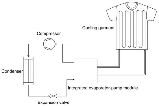
Figure 1.
Schematic diagram of the portable LCG system.
The cooling garment creates a localized cool microenvironment around the wearer, absorbing metabolic heat from the body. This heat is transferred by the circulating water to the integrated evaporator-pump module, where it is exchanged with the refrigerant. Within the VCR cycle, the refrigerant then transports the absorbed heat to the condenser, dissipating it into the ambient environment. The cooling capacity () of the system, representing the heat exchanged in the integrated evaporator-pump module, is related to the power consumption () of the VCR unit and the condenser heat rejection () as follows:
The COP is defined as
The system is designed for ambient temperatures exceeding 50 °C. It operates with a condensation temperature of 60 °C, subcooling of 7 °C, an evaporation temperature of 15 °C, and super-heating of 5 °C. It targets a theoretical cooling capacity of 150 W. This design goal accounts for the optimized performance of the miniature rotary compressor and integrated evaporator-pump module under high-temperature conditions. The R134a refrigeration cycle for the VCR unit is analyzed via the pressure–enthalpy diagram in Figure 2, generated using CoolPack [18]. In this cycle, point 1 denotes the compressor suction port, point 2 represents the compressor discharge port, point 3 denotes the condenser outlet, and point 4 represents the evaporator inlet.
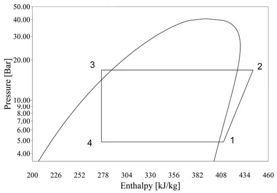
Figure 2.
R134a pressure–enthalpy cycle diagram for the VCR unit.
The cooling capacity and condenser heat flux are determined by the refrigerant mass flow rate () and specific enthalpy differences across the system components:
2.2. Compressor
The miniaturization of compressors is a pivotal factor in the development of portable LCG systems, as it directly impacts system weight and compactness. In small-scale VCR applications, common compressor types include rotary, reciprocating, and linear designs [5]. Linear compressors offer the advantage of flexible installation in any orientation due to their lubrication-free operation; however, their larger size and weight remain prohibitive for lightweight LCG systems, as miniaturization is limited by design challenges like stiffer springs for higher pressure ratios [19] and larger dimensions, e.g., diameter of 60 mm, length of 160 mm, and weight of 1.3 kg in [20], compared to the smaller, lighter rotary compressor used here. In comparison, rotary compressors provide a more compact and lightweight design, a wider evaporation temperature range, and superior cooling capacity per unit volume relative to reciprocating compressors. Consequently, under existing technological constraints, miniature rotary compressors emerge as the preferred choice for optimizing LCG system performance.
The compressor CSMC-Q0192100 from Coolingstyle Co., Ltd. (Shenzhen, China), was chosen for the VCR unit, as depicted in Figure 3 [21]. This compressor, with a diameter of 56 mm, a height of 88 mm, and a mass of 0.85 kg, is powered by a 24 V DC supply, ensuring compatibility with battery-driven operation. It incorporates a DC brushless variable frequency motor, offering an adjustable speed range of 1200 to 6300 rpm and a displacement of 1.9 cm3. The refrigerant mass flow rate is directly proportional to the compressor speed, as expressed by the following equation:
where represents volumetric efficiency, is the refrigerant density, is the compressor displacement, and is the rotational speed in rpm. The relationship between compressor speed and cooling capacity can be further correlated using Equations (3) and (5), enabling the precise control of thermal output.
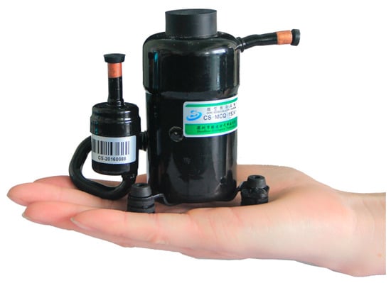
Figure 3.
Miniature rotary compressor (CSMC-Q0192100).
2.3. Condenser
The condenser dissipates heat from the refrigeration system into the environment. This study used a brazed aluminum parallel flow condenser (Figure 4), surpassing traditional round-tube designs in compactness and heat transfer efficiency [22]. It features header tubes, flat tubes, and louvered fins. Internal baffles in the header tubes segment the refrigerant flow into multiple paths, optimizing heat dissipation, while the louvered fins disrupt boundary layer growth, enhancing air-side heat transfer efficiency [23]. The design was optimized through parametric modeling to enhance both air-side and refrigerant-side heat transfer coefficients.
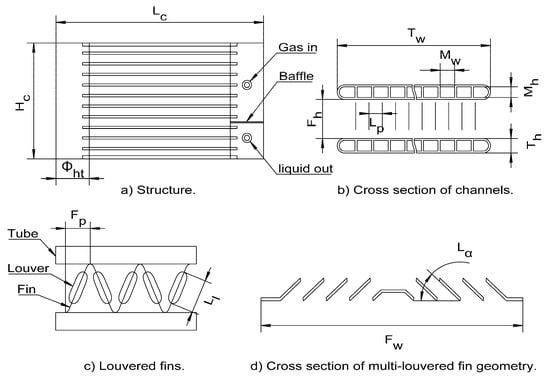
Figure 4.
Brazed aluminum parallel flow condenser design.
For the air side, heat transfer and pressure drop characteristics have been extensively studied using the Colburn factor () and Fanning friction factor () [24]. In this study, these two factors were calculated according to the method presented by Dong et al. [25].
where is the Reynolds number based on the louver pitch . The Nusselt number () is then derived as
The convective heat transfer coefficient on the air side () is calculated as
The flow on the refrigerant side is divided into three states: superheated, two-phase (gas–liquid), and subcooled. Single-phase heat transfer in the superheated and subcooled regions was calculated using the correlation from Adams et al. [26], which is applicable to non-circular microchannels. Adams et al.’s correlation was validated for non-circular channels with hydraulic diameters around 1.13 mm, while our channels have a hydraulic diameter of approximately 0.6 mm. Although this may introduce some inaccuracies, the correlation remains the most applicable available model for our microchannel geometry, given the limited alternatives for smaller diameters. For two-phase flow, the model presented by Wang and Rose [27] was used, which provides a theoretical framework for film condensation in horizontal noncircular section microchannels. This model accounts for the specific geometry of our rectangular channels and includes the effects of surface tension and gravity on the condensate film. The local heat flux for sidewalls is given by
where is the local heat flux, is a parameter related to the interface temperature drop, is the thermal conductivity of the condensate, is the condensate film thickness, is the saturation temperature of the vapor, and is the wall temperature. Additionally, the mean heat transfer coefficient is calculated as
where is the mean heat flux and is the mean temperature difference, requiring numerical solutions of differential equations, which were computed accordingly.
The key design parameters are listed in Table 1, ensuring the construction of a compact and efficient condenser.

Table 1.
Design parameters of the condenser.
2.4. Expansion Valve
The expansion device is a critical component in refrigeration systems, creating the essential pressure difference between the condenser and evaporator to enable refrigerant expansion and subsequent heat absorption in the evaporator.
In compact refrigeration systems, capillary tubes are the most widely used expansion devices [5]. This expansion solution offers distinct advantages, including structural simplicity, minimal spatial requirements, and cost-effectiveness [28]. Numerous studies have investigated methodologies for determining capillary tube dimensions [29,30]. Building upon these established approaches, this study experimentally determined the optimal internal diameter and length of the capillary tube through systematic testing.
2.5. Integrated Evaporator-Pump Module
Microchannel heat exchangers, characterized by their compact size and high efficiency, are extensively utilized in vapor compression refrigeration systems. Significant research has been conducted on theoretical calculation methods for these heat exchangers [31,32].
To achieve further reductions in system volume and weight, an integrated approach combining the microchannel heat exchanger with a water pump has been developed and patented as a viable solution [33]. This study introduces a novel integrated evaporator-pump module (Figure 5) by directly connecting the water pump ports to the heat exchanger. This integration reduces system volume and weight compared to separate designs. The technical specifications of this integrated module are detailed in Table 2.
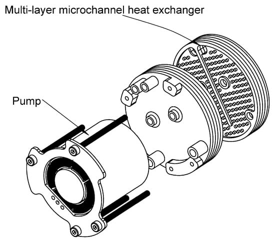
Figure 5.
Integrated evaporator-pump module.
Table 2.
Design parameters of the integrated module.
The main parameters of the LCG system, including dimensions, weight, and battery specifications, are summarized in Table 3. A photograph of the LCG system worn by a user, showcasing the waist-mounted refrigeration unit, cooling garment, and connecting pipes, is shown in Figure 6.
Table 3.
Main parameters of the LCG system.
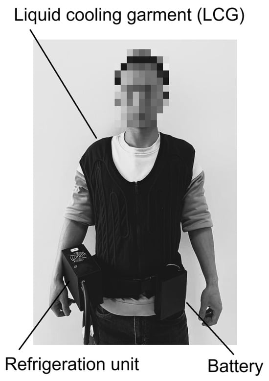
Figure 6.
LCG system worn by a user.
3. Experimental Study and Results
The experimental evaluation of the LCG system was conducted to assess its performance in extreme high-temperature environments. The study comprised two main components: human trials to evaluate physiological responses (skin temperature and heart rate) and subjective thermal comfort and performance tests to measure the cooling capacity and COP of the refrigeration unit. The refrigeration unit is powered by a battery with a voltage range of 21 V to 29.4 V and a capacity of 8 Ah, enabling operation for approximately 1.2 h at full load. The LCG system features a waist-mounted refrigeration unit connected to the garment via water tubes for circulating chilled water. After extensive testing, the optimal capillary tube dimensions were determined to be 1.0 mm in diameter and 1.2 m in length, with a refrigerant charge of 60 g.
3.1. Human Trials
Human trials were conducted in a climatic chamber to evaluate the LCG system’s effectiveness under high-temperature conditions. The chamber maintained a relative humidity of 60% ± 3% RH and an air speed below 0.3 m/s. Eight male participants, aged 23–30 years, with heights of 170–178 cm and weights of 68–76 kg, participated in the study. All were in good health with no medical history affecting heat response and provided written informed consent. The study adhered to the Declaration of Helsinki and was approved by the internal review board of Shenzhen Coolingstyle Technology Co., Ltd. (Shenzhen, China).
Four test conditions were evaluated, as shown in Table 4.
Table 4.
Test conditions for human trials.
The experimental setup for two test conditions (Conditions 2 and 4) is shown in Figure 7. Figure 7a shows a participant walking on a treadmill at 4 km/h while wearing the VCR-LCG in a 35 °C environment. Figure 7b shows a participant sitting in a 40 °C environment while wearing the VCR-LCG.
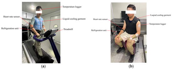
Figure 7.
Test conditions for VCR-LCG: (a) Condition 2 (35 °C, walking, VCR-LCG); (b) Condition 4 (40 °C, sitting, VCR-LCG).
Each participant completed all four conditions in a randomized order to minimize sequence effects. For each test, participants were allowed to acclimatize in the climatic chamber for 15 min before data collection began. Tests lasted 45 min, with skin temperature and heart rate recorded using iButton Temperature Loggers (Model DS1923, ±0.5 °C accuracy; Wdsen Electronic Technology Co., Ltd., Shanghai, China) and Polar OH1+ optical heart rate sensors (±2% accuracy; Polar Electro Oy, Kempele, Finland), alongside subjective thermal comfort.
3.1.1. Skin Temperature
Skin temperature was measured at eight points: the forehead (), right scapula (), left upper chest (), right upper arm (), left lower arm (), left hand (), right thigh (), and left calf (). The mean skin temperature () was calculated according to ISO 9886 standard [34] as
Figure 8 illustrates the mean skin temperature over time for the four test conditions. In the 35 °C walking condition without the VCR-LCG, the mean skin temperature reached a final stable value of approximately 35.94 °C, with an average of 35.26 °C and a peak of 35.94 °C during the 45 min test. When the VCR-LCG was worn in the same condition, the mean skin temperature stabilized at around 35.6 °C, with an average of 35.19 °C and a peak of 35.69 °C. The VCR-LCG reduced the final stable temperature by 0.34 °C, the average temperature by 0.07 °C, and the peak temperature by 0.25 °C, demonstrating its ability to effectively dissipate heat and maintain a lower skin temperature during physical activity in a warm environment. In the 40 °C sitting condition without the VCR-LCG, the mean skin temperature reached a final stable value of approximately 36.29 °C, with an average of 35.64 °C and a peak of 36.29 °C. With the VCR-LCG, the mean skin temperature stabilized at around 35.2 °C, with an average of 35.09 °C and a peak of 35.22 °C. The reductions of 1.09 °C in final stable temperature, 0.55 °C in average temperature, and 1.07 °C in peak temperature highlight the VCR-LCG’s effectiveness in maintaining a stable and lower skin temperature in sedentary conditions, likely due to reduced metabolic heat production allowing for more efficient cooling.
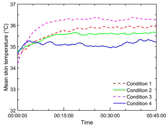
Figure 8.
Mean skin temperature over time for four test conditions.
3.1.2. Heart Rate
Figure 9 presents the heart rate trends over time for the four test conditions, measured continuously using wearable sensors. In the 35 °C walking condition without the VCR-LCG, the heart rate averaged 114.3 bpm, ranging from 108 to 122 bpm, reflecting the cardiovascular strain from physical activity in a warm environment. When the VCR-LCG was worn in the same condition, the heart rate averaged 115.8 bpm, with a range of 112 to 122 bpm. The slight increase of 1.5 bpm suggests that the cooling effect had a limited impact on reducing cardiovascular load during moderate exercise, likely because the physical demands of walking dominated heart rate responses, overshadowing the cooling benefit. However, participants reported a reduced sense of exertion with the VCR-LCG, indicating a subjective improvement not fully captured by heart rate data. In the 40 °C sitting condition without the VCR-LCG, the heart rate averaged 98.2 bpm, ranging from 88 to 108 bpm, with a gradual increase due to thermal stress. With the VCR-LCG, the heart rate averaged 88.0 bpm, ranging from 79 to 98 bpm, being consistently lower throughout the test. The reduction of 10.2 bpm on average, with a maximum decrease of 14 bpm at specific time points (e.g., 29:10), highlights the VCR-LCG’s effectiveness in alleviating thermal stress in sedentary conditions, where lower metabolic heat allows the cooling system to significantly reduce cardiovascular strain.
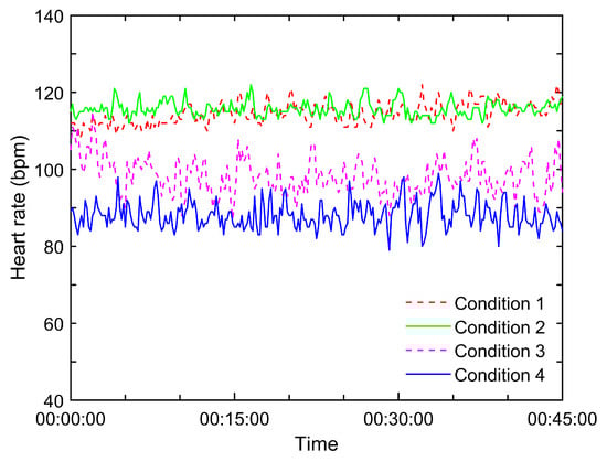
Figure 9.
Heart rate trends over time for the four test conditions.
3.1.3. Subjective Thermal Comfort
Figure 10 displays the mean thermal sensation votes (TSVs) and thermal comfort votes (TCVs) over time for the four test conditions, based on ISO 10551 standard [35], with eight participants providing votes every 5 min. The TSV and TCV scales are presented in Table 5.
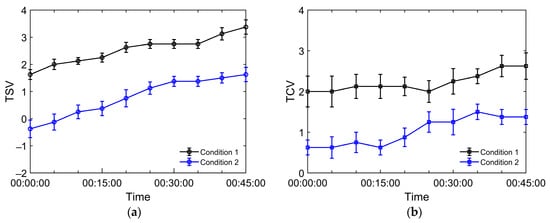
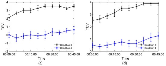
Figure 10.
Mean thermal sensation votes (TSVs) and thermal comfort votes (TCVs) over time for four test conditions. (a) TSV for Conditions 1 and 2; (b) TCV for Conditions 1 and 2; (c) TSV for Conditions 3 and 4; (d) TCV for Conditions 3 and 4.
Table 5.
Scale of thermal sensation and thermal comfort.
In the 35 °C walking condition without the VCR-LCG, the mean TSV increased from 1.63, indicating a slightly warm sensation, to 3.38, corresponding to a hot sensation, reflecting the growing heat stress during physical activity. The mean TCV rose from 2.0, slightly uncomfortable, to 2.63, uncomfortable. When the VCR-LCG was worn, the mean TSV started at −0.38, slightly cool, and reached 1.63, slightly warm, while the mean TCV remained below 1.13, ranging from comfortable to slightly uncomfortable. The reductions of 1.75 units in peak TSV and 1.5 units in peak TCV demonstrate significant improvements in thermal comfort, supported by a two-way repeated-measure ANOVA showing the significant effects of the VCR-LCG on TSV (F (1, 7) = 62.14, p < 0.001) and TCV (F (1, 7) = 89.33, p < 0.001). In the 40 °C sitting condition without the VCR-LCG, the mean TSV increased from 2.13, warm, to 3.38, hot, and the mean TCV rose from 2.63, uncomfortable, to 3.88, very uncomfortable. With the VCR-LCG, the mean TSV started at 0.0, neutral, and peaked at 0.88, slightly warm, while the mean TCV stayed below 1.25, comfortable to slightly uncomfortable. The reductions of 2.5 units in peak TSV and 2.63 units in peak TCV indicate substantial thermal comfort improvement, confirmed by ANOVA results showing significant effects on TSV (F (1, 7) = 94.27, p < 0.001) and TCV (F (1, 7) = 112.56, p < 0.001).
3.2. Refrigeration Unit Performance
Figure 11 illustrates the experimental setup for testing the refrigeration unit’s performance. The unit was powered by the battery, with a power meter measuring electrical consumption. The refrigeration unit was connected in a loop to an electric heater and a flow meter to measure water flow rate. Two thermometers recorded the inlet and outlet water temperatures.
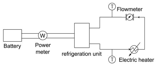
Figure 11.
Experimental setup for refrigeration unit testing.
The cooling capacity was calculated as
Tests were conducted at ambient temperatures ranging from 35 °C to 60 °C, with outlet water temperatures from 10 °C to 24 °C. The compressor operated at its maximum rotational speed of 6300 rpm. Each data point represents the average of three tests, with a variability of less than 5%. Figure 12 shows the cooling capacity versus ambient and outlet water temperatures at the compressor’s maximum rotational speed of 6300 rpm, and Figure 13 shows the COP versus ambient and outlet water temperatures at the compressor’s maximum rotational speed of 6300 rpm.
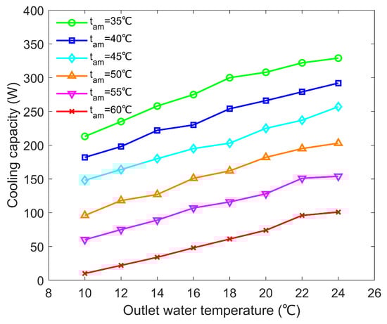
Figure 12.
Cooling capacity as a function of ambient temperature (35–60 °C) and outlet water temperature (10–24 °C) at 6300 rpm.
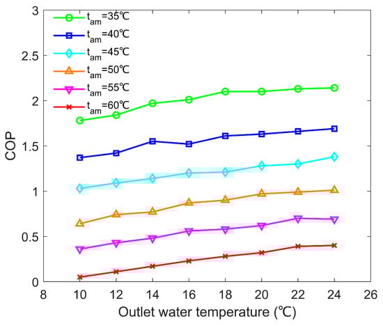
Figure 13.
COP as a function of ambient temperature (35–60 °C) and outlet water temperature (10–24 °C) at 6300 rpm.
The cooling capacity decreased as ambient temperature increased and outlet water temperature decreased, reaching 329 W at an ambient temperature of 35 °C and an outlet water temperature of 24 °C, but dropping to 10 W at an ambient temperature of 60 °C and an outlet water temperature of 10 °C. At the design target condition of an ambient temperature of 55 °C and an outlet water temperature of 22 °C, the cooling capacity was 151 W, slightly above the theoretical target of 150 W, indicating sufficient performance for human heat dissipation needs. This trend reflects the system’s sensitivity to condenser heat rejection efficiency, which diminishes in extreme heat, though the high cooling capacity at lower ambient temperatures highlights the effectiveness of the brazed aluminum condenser and integrated evaporator-pump module. The COP exhibited a similar pattern, ranging from 2.14 at an ambient temperature of 35 °C and an outlet water temperature of 24 °C to 0.05 at an ambient temperature of 60 °C and an outlet water temperature of 10 °C. At an ambient temperature of 55 °C and an outlet water temperature of 22 °C, the COP was 0.70, indicating moderate energy efficiency under extreme conditions. The peak COP at lower ambient temperatures results from reduced compressor work and enhanced heat transfer efficiency, while the sharp decline at higher temperatures underscores the challenge of maintaining efficiency when condenser performance is limited. These results demonstrate the refrigeration unit’s ability to provide adequate cooling in high-temperature environments, though efficiency decreases significantly above 55 °C, suggesting the potential for further optimization, such as enhanced condenser heat dissipation.
3.3. Critical Considerations
This LCG system, with a total weight of 3.6 kg and a refrigeration unit weighing 1.99 kg, achieves a 151 W cooling capacity at an ambient temperature of 55 °C and an outlet water temperature of 22 °C, demonstrating robust performance in extreme heat (>50 °C). The 1.99 kg refrigeration unit is the lightest among the comparable VCR-based LCGs available. For instance, Morriesen et al. [13] achieved a cooling capacity of 150 W with a 3.5 kg system (35 °C ambient), and Ernst and Garimella [16] reached a capacity of 300 W with a 5.7 kg system (37.7–47.5 °C ambient). Yuan et al. [14] reported a cooling capacity of 260 W at an ambient temperature of 50 °C and an outlet water temperature of 24 °C. Performance disparities arise from varying test conditions (ambient temperature, activity state, and measurement methods) and a lack of unified standards for cooling garment evaluation. The COP of 0.70 at 55 °C is lower than the value of 2.14 at 35 °C, reflecting condenser efficiency challenges in extreme heat.
Mean skin temperature reductions in the final stable state of 0.34 °C (walking) and 1.09 °C (sitting) demonstrate the LCG’s effectiveness in thermal regulation. However, these values may be limited by the ISO 9886 standard, which assigns high weights to head and limb temperatures (e.g., forehead, arms, legs), outside LCG coverage areas (torso, back), potentially underestimating cooling effectiveness for the torso and back.
The limitations of this study include the male-only participant pool (eight young males), excluding middle-aged and older individuals and women, the 45 min test duration limiting long-term reliability insights, the use of a high-GWP refrigerant, R134a, and the lack of exploration of the system’s performance at high humidities due to condenser efficiency drops.
Future challenges include applying low-GWP refrigerants (e.g., R290, R32, R1234yf) in this field, enhancing condenser efficiency at high temperatures, and optimizing control algorithms to improve energy efficiency, thereby reducing power consumption and extending battery life.
4. Conclusions
This study developed a 3.6 kg portable liquid cooling garment (LCG) with a 1.99 kg refrigeration unit, achieving a 151 W cooling capacity and a COP of 0.70 at an ambient temperature of 55 °C and an outlet water temperature of 22 °C, meeting extreme heat (>50 °C) demands. Human trials with eight male participants at 35 °C (walking) and 40 °C (sitting) indicated that the liquid cooling garment system reduced thermal comfort votes by 1.5 (2.63 to 1.13) and 2.63 (3.88 to 1.25), mean skin temperature in the final stable state by 0.34 °C and 1.09 °C, and heart rate by 10.2 bpm (sitting), confirming effective thermal regulation. The LCG is suited to applications in industrial safety (e.g., construction, mining, smelting), military operations (e.g., combat, desert training), and emergency response (e.g., firefighting, disaster rescue). The limitations of this study include the 45 min test duration, the male-only participant pool excluding middle-aged and older individuals and women, and its use of high-GWP R134a. Future work will explore applying low-GWP refrigerants (e.g., R290, R32, R1234yf) in this field, improving condenser efficiency at high temperatures, and optimizing control algorithms to improve energy efficiency, thereby reducing power consumption and extending battery life.
Author Contributions
Conceptualization, Y.Z. and Y.H.; methodology, Y.Z. and Y.H.; formal analysis, W.X.; data curation, W.X.; writing—original draft preparation, Y.Z. and Y.H.; writing—review and editing, W.X. All authors have read and agreed to the published version of the manuscript.
Funding
This research received no external funding.
Institutional Review Board Statement
The study was conducted in accordance with the Declaration of Helsinki, and the protocol was approved by the Ethics Committee of Ethics Review Committee of Shenzhen Coolingstyle Technology Co., Ltd. (IRB-2025-002, 10 March 2025).
Informed Consent Statement
Informed consent was obtained from all subjects involved in this study.
Data Availability Statement
The datasets used during the present study are available from the corresponding author upon reasonable request.
Conflicts of Interest
Yuancheng Zhu and Weiguo Xiong are both employed by the company Shenzhen Coolingstyle Technology Co., Ltd. The remaining authors declare that the research was conducted in the absence of any commercial or financial relationships that could be construed as a potential conflict of interest.
Nomenclature
| c | specific heat, [Jkg−1K−1] | Greek symbols | |
| Fh | fin height, [m] | α | convective heat transfer coefficient, [Wm−2K−1] |
| Fp | fin pitch, [m] | δ | condensate film thickness, [–] |
| Fw | fin width, [m] | ζ | a parameter related to the interface temperature drop, [–] |
| Fδ | fin thickness, [m] | η | volumetric efficiency, [–] |
| f | Fanning friction factor, [–] | λ | thermal conductivity, [Wm−1K−1] |
| H | height, [m] | ρ | density, [kgm−3] |
| h | specific enthalpy of refrigerant, [Jkg−1] | Φht | header diameter, [m] |
| j | Colburn factor, [–] | ||
| L | length, [m] | Subscripts | |
| Ll | louver length, [m] | a | air or air-side |
| Lp | louver pitch, [m] | am | ambience |
| Lα | louver angle, [deg] | c | condenser |
| Mh | height of channels in flat tube, [m] | e | evaporator |
| Mw | width of channels in flat tube, [m] | F | forehead |
| Nu | Nusselt number, [–] | i | inlet |
| n | rotary speed of compressor, [rpm] | l | liquid phase |
| Pr | Prandtl number, [–] | Lc | left calf |
| Q | heat transfer power, [W] | Lh | left hand |
| q | local heat flux, [Wm−2] | Lla | left lower arm |
| mean heat flux, [Wm−2] | Luc | left upper chest | |
| qm,r | refrigerant mass flow rate, [kgs−1] | o | outlet |
| qv,w | volumetric flow rate of water, [m3s−1] | r | refrigerant |
| Reynolds number on the louver pitch, [–] | Rs | right scapula | |
| Th | flat tube height, [m] | Rt | right thigh |
| Tw | flat tube width, [m] | Rua | right upper arm |
| ΔT | mean temperature difference, [°C] | s | saturation |
| t | temperature, [°C] | tp | two phases |
| mean temperature, [°C] | w | water or wall | |
| Vdis | compressor displacement, [m3] | 1 | compressor suction port |
| W | power consumption, [W] | 2 | compressor discharge port |
| 3 | condenser outlet | ||
| 4 | evaporator inlet | ||
References
- Cramer, M.N.; Gagnon, D.; Laitano, O.; Crandall, C.G. Human Temperature Regulation under Heat Stress in Health, Disease, and Injury. Physiol. Rev. 2022, 102, 1907–1989. [Google Scholar] [CrossRef]
- Sajjad, U.; Hamid, K.; Tauseef-ur-Rehman; Sultan, M.; Abbas, N.; Ali, H.M.; Imran, M.; Muneeshwaran, M.; Chang, J.-Y.; Wang, C.-C. Personal Thermal Management—A Review on Strategies, Progress, and Prospects. Int. Commun. Heat Mass Transf. 2022, 130, 105739. [Google Scholar] [CrossRef]
- Kjellstrom, T.; Briggs, D.; Freyberg, C.; Lemke, B.; Otto, M.; Hyatt, O. Heat, Human Performance, and Occupational Health: A Key Issue for the Assessment of Global Climate Change Impacts. Annu. Rev. Public Health 2016, 37, 97–112. [Google Scholar] [CrossRef] [PubMed]
- Amjed, A.A.; Ali, L.F. Liquid Cooling Garment Configuration and Investigation: A Classifying and Comparative Review. Int. Commun. Heat Mass Transf. 2024, 159, 108114. [Google Scholar] [CrossRef]
- Silva-Romero, J.C.; Belman-Flores, J.M.; Aceves, S.M. A Review of Small-Scale Vapor Compression Refrigeration Technologies. Appl. Sci. 2024, 14, 3069. [Google Scholar] [CrossRef]
- Bouhezza, A.; Laouer, A.; Ismail, K.A.R.; Faraji, H.; Khuda, M.A.; Teggar, M.; Lino, F.A.M.; Henríquez, J.R.; Rodríguez, D. Effective Techniques for Performance Improvement of Phase Change Material Applications: A Review. J. Energy Storage 2025, 105, 114671. [Google Scholar] [CrossRef]
- Xu, H.; Cao, B.; Gao, L.; Wang, F.; Jin, G.; Liu, Z. Personal Cooling Garments with Phase Change Material Packages—A Critical Review of Challenges, Solutions and Recent Progress. Build. Environ. 2024, 250, 111169. [Google Scholar] [CrossRef]
- Wang, S.; Gui, X.; Liu, T.; Huang, Y.; Ding, L. Experimental Study on a Novel Phase Change Cooling Garment to Improve the Thermal Comfort of Live-Line Workers. Int. J. Ind. Ergon. 2025, 108, 103774. [Google Scholar] [CrossRef]
- Feng, T.; Wang, J.; Sun, E.; Di Buono, A.; Chen, R. Flexible Thermoelectric Active Cooling Garment to Combat Extreme Heat. Adv. Mater. Technol. 2025, 10, 2401690. [Google Scholar] [CrossRef]
- Newby, S.; Mirihanage, W.; Fernando, A. Body Heat Energy Driven Knitted Thermoelectric Garments with Personal Cooling. Appl. Therm. Eng. 2025, 258, 124546. [Google Scholar] [CrossRef]
- Liu, B.; Zhang, R.; Wu, Y.; Wang, Y.; Yu, T.; Li, X.; Pu, M.; Ma, X.; Luo, X. Radiative Cooling and Protective Clothing Through Lamination of Hierarchically Porous Membrane. Adv. Mater. Technol. 2024, 9, 2301808. [Google Scholar] [CrossRef]
- Song, W.; Ding, Q.; Huang, M.; Xie, X.; Li, X. Meta-Analysis Study on the Effects of Personal Cooling Strategies in Reducing Human Heat Stress: Possible Application to Medical Workers. J. Build. Eng. 2024, 85, 108685. [Google Scholar] [CrossRef]
- Morriesen, A.; Resende, F.E.; Ramos, L.W.S.L.; Couto, P.R.C.; Ribeiro, G.B. Personal Cooling System Based on Vapor Compression Cycle for Stock Car Racing Drivers. In Proceedings of the International Refrigeration and Air Conditioning Conference, West Lafayette, IN, USA, 16–19 July 2012. [Google Scholar]
- Yuan, W.; Yang, B.; Yang, Y.; Ren, K.; Xu, J.; Liao, Y. Development and Experimental Study of the Characteristics of a Prototype Miniature Vapor Compression Refrigerator. Appl. Energy 2015, 143, 47–57. [Google Scholar] [CrossRef]
- Elbel, S.; Bowers, C.D.; Zhao, H.; Park, S.; Hrnjak, P.S. Development of Microclimate Cooling Systems for Increased Thermal Comfort of Individuals. In Proceedings of the International Refrigeration and Air Conditioning Conference, West Lafayette, IN, USA, 16–19 July 2012. [Google Scholar]
- Ernst, T.C.; Garimella, S. Demonstration of a Wearable Cooling System for Elevated Ambient Temperature Duty Personnel. Appl. Therm. Eng. 2013, 60, 316–324. [Google Scholar] [CrossRef]
- Gale, J.; Cesmeci, S. Design of a Miniature HVAC System to Function As a Multipurpose Cooling Shirt. In Proceedings of the ASME International Mechanical Engineering Congress and Exposition, Columbus, OH, USA, 30 October 2022. [Google Scholar]
- Technical University of Denmark. CoolPack: Simulation Tools for Refrigeration Systems; Technical University of Denmark: Copenhagen, Denmark, 1999. [Google Scholar]
- Liang, K. A Review of Linear Compressors for Refrigeration. Int. J. Refrig. 2017, 84, 253–273. [Google Scholar] [CrossRef]
- Ribeiro, G.B. Development of a High Ambient Temperature Cooling Unit Based on Microcompressor Technology. In Proceedings of the International Refrigeration and Air Conditioning Conference, West Lafayette, IN, USA, 16–19 July 2012. [Google Scholar]
- Coolingstyle. 019 Miniature Compressor. Coolingstyle. 2025. Available online: https://coolingstyle.com/019-miniature-compressor/ (accessed on 5 January 2025).
- Chang, Y.-P.; Tsai, R.; Hwang, J.-W. Condensing Heat Transfer Characteristics of Aluminum Flat Tube. Appl. Therm. Eng. 1997, 17, 1055–1065. [Google Scholar] [CrossRef]
- Dodiya, K.; Bhatt, N.; Lai, F. Louvered Fin Compact Heat Exchanger: A Comprehensive Review. Int. J. Ambient. Energy 2022, 43, 3545–3559. [Google Scholar] [CrossRef]
- Saleem, A.; Kim, M.-H. CFD Analysis on the Air-Side Thermal-Hydraulic Performance of Multi-Louvered Fin Heat Exchangers at Low Reynolds Numbers. Energies 2017, 10, 823. [Google Scholar] [CrossRef]
- Dong, J.; Chen, J.; Chen, Z.; Zhang, W.; Zhou, Y. Heat Transfer and Pressure Drop Correlations for the Multi-Louvered Fin Compact Heat Exchangers. Energy Convers. Manag. 2007, 48, 1506–1515. [Google Scholar] [CrossRef]
- Adams, T.M.; Dowling, M.F.; Abdel-Khalik, S.I.; Jeter, S.M. Applicability of Traditional Turbulent Single-Phase Forced Convection Correlations to Non-Circular Microchannels. Int. J. Heat Mass Transf. 1999, 42, 4411–4415. [Google Scholar] [CrossRef]
- Wang, H.S.; Rose, J.W. A Theory of Film Condensation in Horizontal Noncircular Section Microchannels. J. Heat Transf. 2005, 127, 1096–1105. [Google Scholar] [CrossRef]
- Heydari, A. Miniature Vapor Compression Refrigeration Systems for Active Cooling of High Performance Computers. In Proceedings of the Eighth Intersociety Conference on Thermal and Thermomechanical Phenomena in Electronic Systems (ITherm 2002), San Diego, CA, USA, 30 May–1 June 2002; pp. 371–378. [Google Scholar]
- Melo, C.; Ferreira, R.T.S.; Neto, C.B.; Gonçalves, J.M.; Mezavila, M.M. An Experimental Analysis of Adiabatic Capillary Tubes. Appl. Therm. Eng. 1999, 19, 669–684. [Google Scholar] [CrossRef]
- Chingulpitak, S.; Wongwises, S. Two-Phase Flow Model of Refrigerants Flowing through Helically Coiled Capillary Tubes. Appl. Therm. Eng. 2010, 30, 1927–1936. [Google Scholar] [CrossRef]
- Kandlikar, S.G.; Balasubramanian, P. An Extension of the Flow Boiling Correlation to Transition, Laminar, and Deep Laminar Flows in Minichannels and Microchannels. Heat Transf. Eng. 2004, 25, 86–93. [Google Scholar] [CrossRef]
- Lee, J.; Mudawar, I. Implementation of Microchannel Evaporator for High-Heat-Flux Refrigeration Cooling Applications. J. Electron. Packag. 2006, 128, 30–37. [Google Scholar] [CrossRef]
- Zhu, Y.; He, Y.; Xiong, W. Yi Zhong Huan Re Shui Beng Zhuang Zhi (A Heat Exchange Water Pump Device in Chinese). Chinese Patent CN118532323B, 15 October 2024. [Google Scholar]
- ISO 9886:2004; Ergonomics—Evaluation of Thermal Strain by Physiological Measurements. International Organization for Standardization (ISO): Geneva, Switzerland, 2004.
- ISO 10551:2019; Ergonomics of the Thermal Environment—Assessment of the Influence of the Thermal Environment Using Subjective Judgement Scales. International Organization for Standardization (ISO): Geneva, Switzerland, 2019.


Disclaimer/Publisher’s Note: The statements, opinions and data contained in all publications are solely those of the individual author(s) and contributor(s) and not of MDPI and/or the editor(s). MDPI and/or the editor(s) disclaim responsibility for any injury to people or property resulting from any ideas, methods, instructions or products referred to in the content. |
© 2025 by the authors. Licensee MDPI, Basel, Switzerland. This article is an open access article distributed under the terms and conditions of the Creative Commons Attribution (CC BY) license (https://creativecommons.org/licenses/by/4.0/).