Abstract
This study investigates the aerodynamic performance of vertical axis wind turbines (VAWTs), focusing on a novel dual-airfoil morphing mechanism for H-type Darrieus turbines. By leveraging the aerodynamic benefits of two distinct airfoil profiles, the proposed design adapts dynamically to varying wind speeds, enhancing overall efficiency. The methodology includes airfoil selection and aerodynamic analysis using the Double Multiple Stream Tube (DMST) model, simulated in QBlade software. The numerical model was validated against established benchmark data, confirming its accuracy. Key findings reveal that among all tested airfoils, the NACA 64(2)-415 airfoil achieves the highest power coefficient at low wind speeds, while the FX 84-W-127 airfoil performs optimally at higher wind speeds. Inspired by biomimetic principles, a morphing strategy and mechanism is proposed to transition seamlessly between these two profiles and enable broader operational adaptability. This innovative approach demonstrates significant potential for improving the energy capture efficiency and viability of VAWTs, contributing to the advancement of renewable wind energy technologies.
1. Introduction
Background and Motivation
In recent years, the energy sector has witnessed significant advancements in technologies categorized as “renewable,” which aim for clean and inexhaustible energy production by harnessing the Earth’s diverse resources. Wind energy is a valuable resource that requires systems designed to harness its kinetic energy and convert it into mechanical power. When this mechanical energy is used to rotate a shaft connected to an electricity generator, the system is referred to as a wind turbine (WT).
The WTs available in the commercial sector are divided into horizontal axis wind turbines (HAWTs) and vertical axis wind turbines (VAWTs) [1,2]. In HAWTs, the shaft rotates horizontally with the blades spinning perpendicularly to the ground, while in VAWTs, the shaft rotates vertically with the blades spinning parallel to the ground. HAWTs have long been the primary choice for commercial electricity generation, thanks to years of extensive research and development [2]. On the other hand, VAWTs are currently being explored in research due to their unique advantages. Compared to HAWTs, VAWTs can operate at lower tip-speed ratios [2] and do not require yaw control mechanisms [3]. They are omnidirectional, i.e., independent of wind direction [4], perform better in turbulent or non-uniform airflow conditions [5], and generate less noise [6], making them simpler and more suitable for installation on rooftops in urban and suburban areas, where wind conditions are often highly variable and intermittent [7]. VAWTs further stand out for their straightforward design, featuring a single moving part, the rotor, and uniform, untwisted blades that are easier to manufacture compared to the twisted and tapered blades of HAWTs. Additionally, most VAWT components are located at ground level, significantly simplifying maintenance [8]. Due to these advantages, VAWTs have gained significance in wind energy research, evidenced by the increasing volume of academic publications [9], addressing diverse VAWT configurations.
The classification of VAWTs is then divided into drag-type (Savonius) turbines and lift-type (Darrieus) turbines [10]. Savonius turbines, although generally less efficient at converting wind energy into usable power, are well suited for small-scale applications due to their simple design and reliability [11]. They also have better startup characteristics against low wind speed compared to Darrieus turbines. On the other hand, Darrieus turbines, patented by Georges Jean Marie Darrieus in 1931 [12], are known for their ability to achieve higher power coefficients, making them more efficient in energy conversion. Darrieus VAWTs are further classified into H-Darrieus, D-Darrieus, and Helical-Darrieus [13]. The H-Darrieus has a simple vertical blade design, the D-Darrieus features double-curved blades for improved efficiency, and the Helical-Darrieus uses helical blades for better torque and reduced noise. The main components of a typical H-Darrieus VAWTs are the blades, central shaft, generator, struts or arms, and the base or support structure. The efficiency of VAWTs is influenced by dynamic stalls, which occur when the rotor blades’ varying angle of attack (AOA) surpasses the static stall threshold. While blade performance may initially improve during dynamic stall, the release of vortices downstream leads to a sharp decline in power generation due to a significant reduction in lift [14].
Conventional VAWTs often suffer from low aerodynamic efficiency, poor self-starting capability, low torque generation, early stall, strong wake interference, and performance constraints across a limited tip-speed ratio (TSR) range. To overcome these limitations, recent studies have explored morphing strategies (blade shape morphing, leading edge morphing, trailing edge morphing, and surface morphing, etc.), inspired by biomimetic principles. These include variable pitch systems (efficiency gains of 13–78.9%), adaptive flaps to reduce wake losses (efficiency gains of 10–54%, Gurney flaps for improved pressure recovery (power efficiency increase of 2.7–37.5%), and deformable airfoils that enhance lift and delay stall (power coefficient increases of 8–90%) [15,16].
The impact of profile changes, including inward semicircular dimples, Gurney flaps, and trailing edge flaps improve the aerodynamics of turbine blades and maximize average torque in VAWTs [17,18]. The authors in [19] compare the performance of a VAWT with and without morphing blades, showing that the proposed morphing approach improves power output by 46.2% of the overall power out. Loth et al. [20] proposed a morphing segmented blade concept for extreme-scale wind turbines to enhance efficiency and reduce weight but highlights limitations like flutter instability and dynamic stall requiring active control. Milojevic et al. [21] presented a novel shape morphing compliant structure with embedded actuators capable of adapting its shape on demand, addressing manufacturing challenges by improving the design methodology to eliminate intersecting structural elements. Zhang et al. [22] developed a dynamic camber morphing wing, including compliant leading and trailing edges, which facilitates significant deflection and enhances aerodynamic performance while preserving structural integrity under aerodynamic and structural loads. Such approaches demonstrate the potential of morphing to significantly improve turbine overall performance and power efficiency.
Various researchers have proposed multiple approaches based on distinct physical considerations. This study presents a dual-airfoil morphing system for H-type Darrieus VAWTs utilizing two distinct airfoil profiles, one suited for low wind speeds and the other for high wind speeds—to improve power efficiency under varying wind conditions. This novel approach combines the aerodynamic advantages of two distinct airfoils, enabling seamless adaptation without complex mechanical systems, inspired by biomimetic design principles observed in nature. The proposed system seeks optimal turbine performance in both low and high wind regimes, significantly improving energy capture while simplifying mechanical complexity.
The key novelties and significant contributions of this research are as outlined below:
- A dual-airfoil profile design is introduced, combining two airfoils with distinct characteristics through a novel morphing transition to enhance power performance under variable wind conditions.
- The new design allows for a low cut-in speed, effectively addressing one of the main issues of Darrieus-type vertical-axis wind turbines, that is, their inability to achieve the starting torque required for high-speed rotation.
- The present study aims to introduce a novel morphing approach to improve the aerodynamic efficiency of VAWTs in fluctuating wind conditions. This research emphasizes idea formulation and numerical analysis, whereas future research will concentrate on implementation and experimental validation.
This manuscript is structured as follows: Section 2 outlines the methodology, including the selection of airfoils and the DMST simulation model. Section 3 introduces the concept of the morphing strategy, mechanism, and its design. Section 4 presents the results and discussion, covering simulation validation and airfoil performance analysis at low and high wind speeds. Section 5 outlines the proposed morphing coefficient of the power (Cp) curve, while Section 6 highlights the main conclusions and future research.
2. Methodology
2.1. Selection of the Airfoils
The selection of airfoils for this study is based on aerodynamic power efficiency and the geometric design feasibility of blade morphing transitions between profiles under low and high wind speed conditions. Airfoils showing high power efficiency over an extensive range of tip-speed ratios (TSRs) were evaluated. In addition to power efficiency, the geometric profile’s cross-sectional suitability for seamless morphing was also considered. Key geometric characteristics of an airfoil, including chord length, camber, and thickness, as illustrated in Figure 1, are well known to significantly influence its aerodynamic performance. VAWTs operate based on the lift force produced by the airfoil [23]. To improve their aerodynamic efficiency, researchers either optimize custom airfoil designs or select the most suitable option from existing ones.
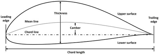
Figure 1.
Main geometric features of an airfoil.
In this study, multiple airfoils with varied characteristics were analyzed, with the airfoil ‘.dat’ files obtained from the UIUC Airfoil Data Site [24]. These airfoils included variations in thickness, camber position, symmetry, and asymmetry, incorporating both 4-digit and 6-digit airfoils from diverse families. It is worth noting that the selection of the airfoil was determined by the flow model illustrated in Figure 2.
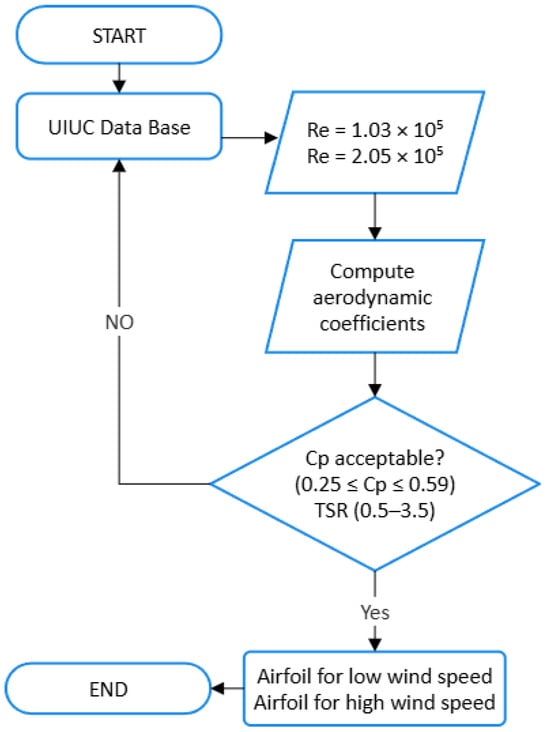
Figure 2.
Flow model of the airfoil selection approach.
The flowchart outlines a process for selecting an airfoil for H-type Darrieus VAWTs, based on the Reynolds number (Re) and aerodynamic power efficiency, aimed at identifying suitable airfoils for varying wind speeds. The airfoils were analyzed at two distinct Res: 1.03 × 10⁵ for low wind speed and 2.05 × 10⁵ for high wind speed. The Re were calculated using (), where is the air density [kg/m3], is the free-stream velocity (wind speed) [m/s], is the characteristic length (chord length of the airfoil) [m], and is the dynamic viscosity of air [Pa.s]. The TSR ranges of 0.5–2.5 and 1.5–3.5 were selected for low and high wind speeds, respectively. These ranges encompass both low-efficiency and optimal aerodynamic performance regions, and they are consistent with the typical operational limits of VAWTs [25]. This selection, for the specified Re, enables observation of the turbine’s behavior under both suboptimal and optimal conditions for performance analysis.
Following the computation of the aerodynamic coefficients, the subsequent step evaluates if the power coefficient is within the acceptable range or if an alternative airfoil selection is required. The lower constraints reflect the typical efficiency of H-type Darrieus VAWTs, and the power coefficient must remain under the Betz limit (0.593) [26], which defines the theoretical maximum efficiency for all wind turbines. By evaluating this range, we ensure that the chosen airfoils encompass those proficient in operating efficiently under both low and high wind speed conditions, thus maximizing energy extraction within actual aerodynamic constraints.
The power extracted by the wind turbine is a fraction of the available wind power, determined by the turbine’s efficiency, represented by the power coefficient Cp, which is a dimensionless parameter [-]. The power output Po [in watts] can be expressed as
where ρ is the air density [kg/m3], A is the swept area of the turbine [m2], and V3∞ is the freestream velocity [m/s]. The actual energy captured by a wind turbine will always be less than 59.3% efficient, which is known as the Betz limit [26].
Po = 1/2 (Cp. ρ. A. V3∞)
It is evident from Equation (1) that the turbine’s power output increases proportionally with the swept area A. The geometry of this area is described by the rotor’s Aspect Ratio (AR), which is defined as follows:
where H is the blade height [m], D is the rotor diameter [m], and Aspect Ratio AR is, therefore, dimensionless [-]. In this study, the design turbine has a blade height of 1.45 m and a rotor diameter of 1.45 m, resulting in an AR of 1.0, as illustrated in Figure 3.
AR = H/D
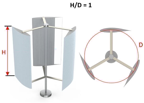
Figure 3.
H-type vertical axis wind turbine Aspect Ratio.
Using numerical analysis allows us to explore design parameters in a more cost-effective and controlled manner compared to building multiple physical prototypes for each configuration. It is worth noting that this study is limited to a computational investigation using the DMST model, which enables detailed analysis of the aerodynamic performance of airfoils under varying wind conditions. These results serve as a foundation for the future implementation of the morphing concept, including experimental validation and mechanical prototyping.
2.2. DMST Simulation Model
Previous research has presented different aerodynamic models for VAWTs, such as the double multiple stream tube (DMST) [27], multiple stream tube (MST) [8], Vortex model [28], cascade [29], and panel methods [30]. Each model has specific strengths and limitations. In this study, the aerodynamic performance and power efficiency of VAWTs were analyzed through using the DMST model, which was originally proposed by Paraschivoiu in 1988 [27]. This model combines the MST approach with the double actuator disk theory [31]. By dividing the rotor plane into multiple vertical stream tubes, the DMST model accounts for both the upstream and downstream flow, iteratively solving for the induction factors and wake effects to determine the aerodynamic forces acting on the turbine blades. An additional actuator disc in the downwind section, representing a secondary induction factor, enables the turbine to interact with the wind flow twice. This enhancement improves the accuracy of predictions compared to the traditional MST method [32]. Additionally, the DMST model requires considerably less computational time compared to the three-dimensional vortex model, while providing enhanced accuracy over the MST model in predicting aerodynamic blade loads [27]. Its main advantage is its simplicity and strong correlation between theoretical predictions and experimental results. However, the DMST model tends to overestimate power for high-solidity turbines and often faces convergence issues, especially downstream and at higher tip-speed ratios [8].
To utilize the DMST method, QBlade software (QBladeCE_2.0.8_win) was employed. QBlade serves as an open-source platform for the design and aerodynamic analysis of wind turbines (HAWTs and VAWTs), developed by David Marten [33]. QBlade seamlessly integrates XFOIL, utilizing the viscous–inviscid panel method to generate 2D airfoil profiles for blade design, calculate lift and drag coefficients, and enable 360° polar extrapolation, all of which are critical for turbine performance analysis [34].
To assess the aerodynamic efficiency of different airfoils for the H-type Darrieus VAWT, several key parameters were examined using QBlade.
The geometric and operational parameters such as blade height, rotor diameter, and tip-speed ratios were selected based on design recommendations and performance data reported in previous studies [35,36]. These choices align with standard configurations commonly used in small-scale Darrieus-type wind turbines. These parameters are crucial for understanding the aerodynamic behavior of the airfoils and assessing the power conversion efficiency under various operating conditions. The parameters used in the simulation are listed in Table 1.

Table 1.
Geometric and operational parameters.
3. Concept of Morphing in Designing VAWTs
This mechanism introduces a novel approach to enhancing the power efficiency of VAWTs through the dynamic morphing of VAWT blades. Unlike conventional airfoil cross-section optimization, morphing mechanisms are typically based on single airfoil designs, such as leading-edge morphing, trailing-edge morphing, and thickness-to-camber ratio optimization. This study combines the aerodynamic advantages of two distinct airfoils to create a blade system that seamlessly adapts to varying wind conditions. By utilizing this mechanism, the airfoil transitions between profiles without requiring complex actuators or heavy mechanical systems, offering a lightweight and efficient solution for optimizing turbine performance in real time. The dual-airfoil morphing approach, depicted in Figure 4, ensures that the turbine operates at its maximum aerodynamic potential in both low and high wind regimes, significantly improving overall energy capture. Figure 5 illustrates the CAD model layout, providing a detailed representation of the morphing airfoil’s design and functionality.
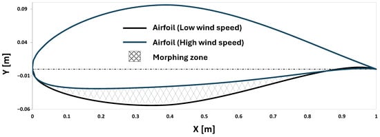
Figure 4.
Blade morphing concept between two airfoils. The morphing zone enables smooth transition from a low wind speed (black) to a high wind speed (blue) airfoil to optimize aerodynamic performance across varying wind speeds.
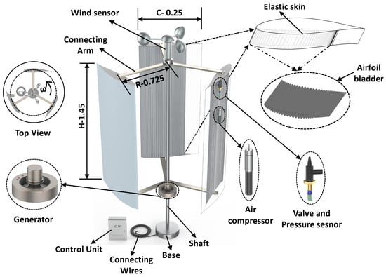
Figure 5.
CAD model layout of the proposed morphing H-Darrieus VAWT design airfoil (dimensions are in meters).
What distinguishes this innovation from other morphing techniques is the use of two complementary airfoil profiles that function optimally under different wind conditions, combined with the application of morphing and biomimetic design principles. In nature, organisms such as birds and fish dynamically adapt their shapes in response to environmental factors, inspiring the development of a morphing system capable of adjusting its aerodynamic properties on demand. By mimicking these biological strategies, the proposed H-type Darrieus VAWT blade design not only enhances performance across a broader range of wind speeds but also simplifies the mechanical complexity typically associated with adaptive systems. The integration of these biomimetic principles into the turbine design opens new possibilities for sustainable and efficient wind energy generation, encouraging further exploration of lightweight, adaptive structures that dynamically respond to changing environmental conditions.
3.1. Morphing Airfoil Strategy for Varying Wind Speeds
The strategies may involve passive and active flow control devices to manage the aerodynamic performance of VAWTs. Building on this, the present study identifies two optimal airfoil profiles: one suitable for low wind speeds and the other for high wind speeds, as detailed in Section 4.2, for performance validation. To effectively bridge these two designs, we propose a prescribed active control strategy that dynamically morphs the airfoil profile from its initial shape at low wind speeds to its final shape at higher wind speeds.
The air bladder will gradually deflate and be positioned at the lower section of the blade (morphing zone) between the thicker and thinner airfoil, as illustrated in Figure 4. To prevent abrupt numerical changes from the initial to final airfoil shape during morphing, the first step is to determine optimal interpolated profile geometries. This can be achieved by reducing thickness through modifications to the lower surface coordinates of the initial airfoil, as illustrated in Figure 6, facilitating a smooth transition between the initial and final profile shapes.
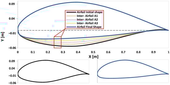
Figure 6.
Prescribed morphing pathway between initial and final airfoil profile shapes.
After establishing the intermediate profiles, to assess the aerodynamic transition during morphing, the fixed intermediate profiles A1, A2, and A3 were simulated under intermediate wind speeds. Their performance is presented and discussed in Section 4.3. These results demonstrate smooth aerodynamic progression from one profile to another. To investigate continuous deformation of the blade to more closely replicate real-time morphing dynamics, future simulations will use computational fluid dynamics (CFD) with user-defined functions (UDFs) to dynamically control airfoil deformation. These UDFs will monitor wind speed and initiate gradual shape changes between the initial and final airfoil profiles, maintaining aerodynamic efficiency during the transition. In doing so, the authors anticipate that several numerical and technical challenges may arise, including mesh quality management during morphing, precise control of shape updates over time, and the added mechanical complexity introduced by the control strategy, which involves moving parts and mechanisms that may present additional challenges.
3.2. Control System Design for Morphing Mechanism
Designing a dynamic control system for morphing H-type VAWTs involves efficiently integrating all components. The design model comprises three blades, a rotor shaft, a generator, a base (support), connecting arms, a controller, an inflatable bladder, sensors, and an air compressor. The shaft is the primary component, conveying the rotational energy created by the turbine blades to the generator, resulting in efficient power transmission. The air compressor inflates the bladder to achieve low-speed airfoil characteristics. Sensors collect input data for the controller, while the control unit serves as the central processing system, receiving data, processing it, and sending signals for actuation.
The system operates in three stages: data acquisition, decision making, and actuation. Figure 7 illustrates the proposed workflow of the control mechanism. The anemometer sensor continuously calculates the wind speed and transfers the data to the control unit, while the pressure sensor monitors the bladder’s internal pressure and provides feedback to the control unit. The control unit compares the wind speed against pre-set thresholds: for low wind speeds (below 6 m/s) it inflates the bladder, and for high wind speeds (above 6 m/s) it deflates the bladder. Based on the wind speed, the control unit activates the air compressor to inflate the bladder. During this process, the pressure sensor ensures the bladder inflates to the required pressure and signals the control unit to stop the compressor once the target pressure is achieved. When wind speeds increase beyond the threshold, the control unit opens the solenoid valve to release air from the bladder, allowing it to deflate.
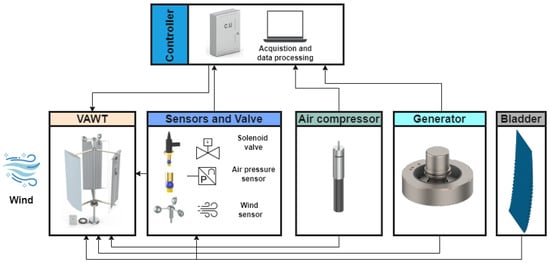
Figure 7.
Workflow of the control mechanism for the morphing H-type VAWT.
The generator, powered by the turbine shaft, supplies the energy needed for the morphing mechanism to function effectively. It is worth noting that shape changes would not occur frequently, as average wind speeds tend to vary over hours rather than minutes. Although detailed energy consumption calculations have not yet been performed in this study, preliminary estimates suggest minimal actuation energy. For instance, commercially available small air compressors—such as those used for inflating beach mattresses—typically operate at 5 V and 5 A, consuming approximately 25 W while handling relatively large air volumes. Given the low actuation frequency and small air volume involved in our model, the expected energy consumption per activation remains extremely low. Consequently, the total energy demand for blade morphing is anticipated to remain well below 1% of the turbine average output, ensuring a positive net energy gain.
4. Results and Discussion
4.1. Numerical Simulation and Model Validation
The current numerical simulations were validated for reliability and accuracy by comparing them with experimental results obtained by Abbot, I. H., and Von Doenhoff [37], using the NACA 0012 airfoil at a Reynolds number of 3.0 × 10⁻⁶. Validation was carried out by analyzing the lift coefficient (CL) and drag coefficient (CD) curves across AOAs from 0° to 20°, using XFOIL integrated within QBlade. The numerical predictions exhibited very good agreement with experimental data, as illustrated in Figure 8.
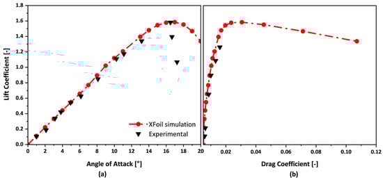
Figure 8.
Comparison between experimental and the adopted aerodynamic model, (a) lift coefficient as function of AOA, (b) lift coefficient as functions of drag coefficients.
Figure 8a presents CL as a function of AOA, demonstrating close alignment with experimental values in the linear region (low to moderate AOA). This confirms that the simulation accurately captures the airfoil’s aerodynamic behavior in this range. Near stall, the experimental data shows a sharper drop in CL than the simulation predicts—a known limitation of XFOIL, which does not account for complex three-dimensional effects such as flow separation at high AOAs [38]. Despite this, the overall trend confirms that XFOIL provides reliable predictions for lift performance in the pre-stall region. Figure 8b compares CL and CD, showing good agreement in the low-drag region. Deviations at higher CL values are attributed to post-stall prediction limitations in XFOIL. Given that this study focuses on airfoil performance at zero angle of attack, these results support the suitability of QBlade for evaluating aerodynamic characteristics under such conditions.
Further validation of the DMST-based numerical simulation was performed using experimental data from Castelli et al. [39] across a range of TSRs. Figure 9 shows the comparison of the power coefficient (Cp) versus TSR. It can be observed that the current simulation results follow the experimental trend, with deviations becoming more pronounced beyond a TSR of 2.5. These differences can be attributed to uncertainties with the experimental data such as boundary conditions, blade surface roughness, wake–blade interactions, and the blade–spoke connection—particularly influential at higher TSRs, as discussed in [40,41,42]. The DMST model also tends to overestimate Cp at high TSRs, due to dynamic stall effects not being considered, which are difficult to predict under conditions of rapidly changing angles of attack and turbulence.
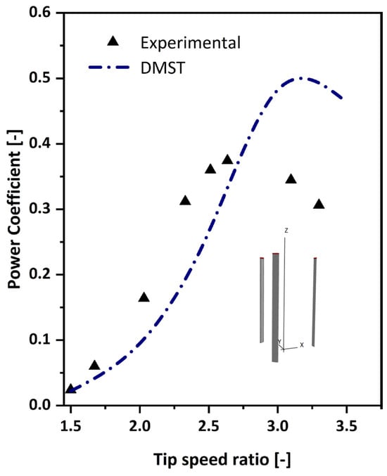
Figure 9.
Comparison of simulated power coefficient as a function of TSR: using Castelli et al. Experimental data [39].
4.2. Airfoil Performance Analysis at Low and High Wind Speeds
This study examined the performance of various airfoil profiles under different wind conditions, specifically 6 m/s for low wind speed and 12 m/sec for high wind speed. To develop a morphing mechanism for a small H-type Darrieus VAWTs, the main goal is to find one airfoil that works best at low wind speeds, with a tip-speed ratio (TSR) of up to 2.5, and another that works best at high wind speeds, above a TSR of 2.5. The simulations were conducted with uniform turbine parameters: rotor radius of 0.725 m, chord length of 0.25 m, swept area of 2.1 m2, TSR range of 0.5 to 3.5, air density (ρ) of 1.225 kg/m3, air viscosity (μ) of 1.789 × 10⁻⁵ kg/m·s, maximum epsilon for convergence (ε) of 1 × 10⁻⁵, and a relaxation factor to 0.3. Furthermore, correction factors, such as tip loss and variable induction factors, were applied to simulate the conditions in more realistic media. An investigation of Cp as a function of TSR was conducted for each airfoil, emphasizing performance under varying wind conditions. Airfoils exhibiting a substantial decline beyond specific TSR values and a low power coefficient were deemed inappropriate for the intended morphing blade design.
Through a narrowed evaluation of the aerodynamic performance of the three-bladed H-type VAWT, utilizing airfoils such as the NACA 64(2)-415, AH 93-W-257, NACA 64(3)-618, AH 93-W-145, AH 93-W-215, AH 93-W-174, Bergey BW-3 (smoothed), FX 84-W-175, SG 6043, and FX 84-W-150, distinct operational regimes were illustrated across the investigated tip-speed ratios. Figure 10 illustrates the correlation between Cp and TSR at wind speeds of 6 m/s, demonstrating varying aerodynamic characteristics over the TSR spectrum.
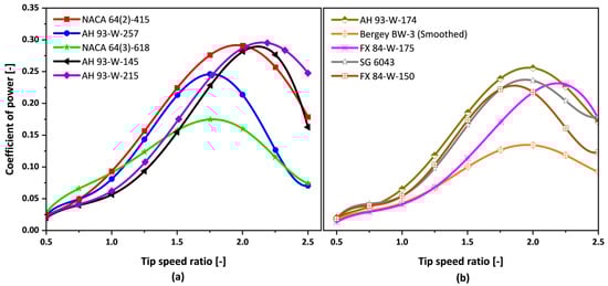
Figure 10.
(a,b) Coefficient of power vs. tip-speed ratio for low wind speed DMST simulation.
Figure 10a indicates the maximum Cp values as follows: Cp is 0.30 at a TSR of 2.0, 0.25 at a TSR of 1.75, 0.17 at a TSR of 1.75, 0.30 at a TSR of 2.25, and 0.28 at a TSR of 2.25. The peak power coefficients correspond to the NACA 64(2)-415, AH 93-W-257, NACA 64(3)-618, AH 93-W-145, and AH 93-W-215 airfoils, respectively. The power coefficient of AH 93-W-215 at TSR values of 2.25 and 2.50 exceeds that of the NACA 64(2)-415; however, the overall power coefficient at a TSR of 0.5 to 2.0 is lower. The NACA 64(3)-618 airfoil demonstrates superior performance relative to other airfoils at a TSR of 1.0 or less, but its performance begins to deteriorate at elevated TSRs. The AH 93-W-257 airfoil exhibited superior Cp values relative to other airfoils at a TSR ≤ 0.75, yet it was lower to the NACA 64(3)-618 at a TSR ≥ 1.15.
Figure 10b shows that the minimum Cp of 0.01 corresponds to the FX 84-W-175 airfoil, while the maximum Cp of 0.25 is associated with the AH 93-W-174 airfoil. In the TSR range of 1.0 to 2.25, the AH 93-W-174 airfoil demonstrates superior power coefficient values relative to other airfoils, establishing it as the most efficient airfoil in Figure 10b, whereas the NACA 64(2)-415 airfoil is notable in Figure 10a.
By comparing the two airfoils’ highest power efficiencies across the investigated TSRs, we find that the NACA 64(2)-415 obtains a peak Cp of 0.30 and the AH 93-W-174 reaches a peak Cp of 0.25. As a result of this, the NACA 64(2)-415 is an efficient airfoil design for TSR values between 0.5 and 2.5, which corresponds to low wind speeds. These findings strongly support the recommendation of the NACA 64(2)-415 for applications involving low wind speeds.
The simulation results for low wind speed conditions were subsequently investigated for high wind speed conditions at a Reynolds number of 2.05 × 10⁵, utilizing the same turbine settings presented in Table 1. This analysis assesses the response of airfoils to elevated wind speed situations and identifies profiles that sustain or enhance efficiency across the evaluated tip-speed ratios. After the preliminary evaluations of several airfoils, a selection comprising the FX 84-W-127, MH 102, MH 104, FX 77-W-153, NACA 4418, NACA 4415, USNP4 (smoothed), FX 83-W-108, SG 6042, and SG 6043 was chosen for comprehensive analysis, as shown in Figure 11.
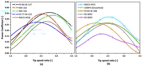
Figure 11.
(a,b) Coefficient of power vs. tip-speed ratio for high wind speed DMST simulation.
Figure 11a illustrates that the FX 84-W-127 and MH 104 attain peak Cp values of 0.35 and 0.33 at a TSR of 2.75, respectively. On the other hand, the MH 102, FX 77-W-153, and NACA 4418 exhibit peak Cp values of 0.34, 0.27, and 0.28 at a TSR of 2.50, respectively. The NACA 4418 airfoil has a minimum power coefficient of 0.04 at a TSR of 1.50, whereas the FX 84-W-127 airfoil demonstrates a maximum power coefficient of 0.35 at a TSR of 2.75. The FX 77-W-153 airfoil shows superior performance regarding the power coefficient relative to other airfoils at a TSR ≤ 2.0; however, it experiences increased drag at elevated TSRs, suggesting it is not an appropriate option for our requirements. The MH 102 airfoil demonstrates a pronounced Cp peak within a specific range of tip-speed ratios (2.0 to 2.5) when compared to the FX 84-W-127, MH 104, FX 77-W-153, and NACA 4418, but experiences a significant decline in performance beyond a TSR of 2.5. The MH 104 and NACA 4418 airfoils exhibit moderate performance at the evaluated tip-speed ratios.
Figure 11b illustrates airfoils comprising the NACA 4415, USNP4 (smoothed), FX 83-W-108, SG 6042, and SG 6043. The USNP4 (smoothed) airfoil demonstrates the highest coefficient of power within the range of 1.5 ≤ TSR ≤ 2.0, whereas the SG 6043 presents the lowest Cp values in this TSR range, with the FX 83-W-108 and SG 6042 showing moderate performance. With an increase in the tip-speed ratio, the USNP4 (smoothed) and SG 6043 airfoils exhibit a significant decline in their power coefficients, indicating their unsuitability for the specified conditions. The power coefficient of the NACA 4415 increases with TSR beyond 2.0, peaking at a TSR of 2.50, followed by a slight decline. The NACA 4415 demonstrates a minimum Cp of 0.06 at a TSR of 1.50 and a maximum Cp of 0.28 at a TSR of 2.50. The maximum power coefficients for the USNP4 (smoothed), FX 83-W-108, SG 6042, and SG 6043 airfoils within the analyzed TSR range are 0.23, 0.23, 0.24, and 0.16, respectively, all of which are below the Cp peak of 0.28 observed for the NACA 4415.
This comparison resulted in the selection of an appropriate airfoil for high wind speeds. Among the airfoils analyzed, the FX 84-W-127 exhibits the highest Cp at 0.35, occurring at a TSR of 2.75. In contrast, the NACA 4415 reaches a peak Cp of 0.28 at a TSR of 2.5. The minimum Cp values are 0.11 at a TSR of 1.50 for the FX 84-W-127 and 0.06 at a TSR of 1.50 for the NACA 4415. The NACA 4415 exhibits an earlier stall effect in comparison to the FX 84-W-127. This indicates that the FX 84-W-127, which exhibited stable and consistently high Cp values throughout the TSR range, provides enhanced and reliable performance in high wind speed conditions. The aerodynamic design of the FX 84-W-127, noted for its streamlined profile and optimal lift-to-drag ratio, makes it effective for energy capture at high wind speeds.
4.3. Aerodynamic Performance of Intermediate Airfoils
To further support the aerodynamic feasibility of the proposed morphing approach, independent simulations were conducted for the intermediate fixed airfoil profiles A1, A2, and A3 at Reynolds numbers of approximately 1.20 × 10⁵, 1.54 × 10⁵, and 1.88 × 10⁵, respectively. As shown in Figure 12, the lift coefficient increases steadily with the angle of attack across the three profiles, while the drag characteristics remain within a similar range. This behavior demonstrates a smooth aerodynamic transition from one profile to another. Although these profiles were evaluated as fixed geometries rather than through continuous deformation, the consistent trend in aerodynamic performance confirms that the morphing transition can be achieved without introducing abrupt aerodynamic changes. The near-linear increase in lift performance validates the strategy’s effectiveness in adapting to varying flow conditions.
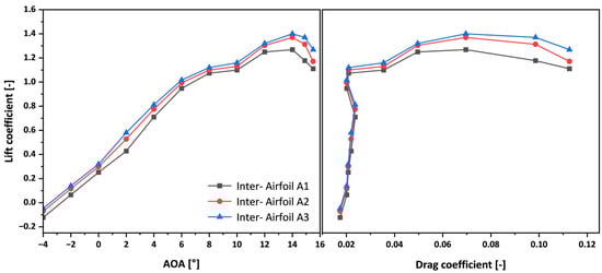
Figure 12.
Aerodynamic performance of intermediate airfoils at Reynolds numbers A1: 1.20 × 10⁵, A2: 1.54 × 10⁵, and A3: 1.88 × 10⁵.
5. Proposed Morphing Coefficient of Power Curve
It is possible to make H-type Darrieus VAWTs work much better using a morphing airfoil design mechanism that changes between two profiles based on the wind speed. At low wind speeds, the turbine operates with an airfoil profile such as that of the NACA 64(2)-415. The increased camber and surface area of the thicker profile generate a strong pressure differential, resulting in higher torque output. This characteristic is critical for overcoming the turbine’s inertia and facilitating reliable startup. Furthermore, the thicker airfoil’s drag, typically a drawback in other conditions, serves as an advantage for initiating rotation at low wind speeds. The power coefficient curve for the thicker profile shows good performance in low tip-speed ratio ranges, showing that it is a good choice for the beginning stages of turbine operation. As wind speed increases, the operational requirements of the turbine shift, necessitating a transition to an airfoil profile such as that of the FX 84-W-127. This new morphing airfoil design takes the best parts of both profiles and combines them into one. The blade shape adapts dynamically to optimize performance across a broad spectrum of wind speeds. During low wind conditions, the airfoil behaves like the NACA 64(2)-415; as wind speed increases, the airfoil transitions to resemble the FX 84-W-127’s profile. This innovative adaptability will enable the turbine to achieve a broader operational range and a higher maximum power coefficient than either of the individual profiles. It is worth noting that the Cp curves provide a comparative baseline, illustrating how the initial and final airfoils perform optimally in different wind-speed ranges—from low to high. This performance distinction forms the aerodynamic basis for the proposed morphing strategy, which aims to combine the strengths of both airfoils across broader operating conditions.
The morphing Cp curve shown in Figure 13 is a conceptual estimate derived from the performance trends of the two fixed airfoils and does not represent an experimentally validated model. While it demonstrates the theoretical aerodynamic potential of blending these profiles, the morphing blade has not yet been physically implemented or tested. Therefore, the proposed approach should be regarded as an early-stage concept. Further development, including mechanical design, control system integration, and physical testing, will be necessary to confirm its feasibility for real-world applications.
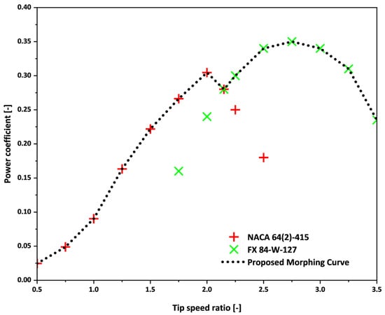
Figure 13.
Power coefficient (Cp) vs. tip-speed ratio (TSR) for the following profiles: (Red marker) NACA 64(2)-415 (Cp at Re = 1.03 × 10⁵), (Green marker) FX 84-W-127 (Cp at Re = 2.05 × 10⁵), and (Black line) proposed morphing Cp curve.
6. Conclusions
This study examined the aerodynamic performance of vertical axis wind turbines (VAWTs), with a focus on a novel dual-airfoil morphing mechanism designed for H-type Darrieus turbines. VAWTs are increasingly recognized for their ability to generate power regardless of wind direction, making them ideal for locations with highly variable wind conditions. The proposed design takes advantage of two distinct airfoil profiles, allowing the turbine to dynamically adapt to different wind speeds. This dynamic adjustment enhances overall efficiency, leading to better energy capture performance across a broader range of operating conditions.
The research methodology involved careful selection of airfoils and conducting aerodynamic analyses using the Double Multiple Stream Tube (DMST) model, simulated through QBlade software. The DMST model is commonly used for wind turbine performance prediction, providing accurate simulations of the turbine’s behavior under varying conditions. Through these simulations, the study evaluated the effectiveness of different airfoils in optimizing turbine performance across various wind speeds.
The findings reveal that the NACA 64(2)-415 airfoil performs best at lower wind speeds, achieving the highest power coefficient in those conditions. Meanwhile, the FX 84-W-127 airfoil outperforms others at higher wind speeds. These results highlight the importance of tailoring airfoil choices to specific wind conditions to maximize efficiency.
Inspired by biomimetic principles, the study introduces a morphing mechanism that enables the turbine to seamlessly transition between these two airfoils. This mechanism allows the turbine to adapt to changing wind speeds, ensuring optimal performance in varying conditions. The ability to shift between airfoil profiles in real time expands the turbine’s operational range and improves its energy capture efficiency.
This innovative approach offers significant potential for enhancing the performance and practical viability of VAWTs. By improving adaptability and efficiency, the proposed design could play an important role in advancing renewable wind energy technologies and making VAWTs a more competitive option for large-scale energy production.
It is important to note that while QBlade provides a robust framework for simulating aerodynamic performance using the DMST model, it has certain limitations. The software is based on simple assumptions that might not fully explain complex flow phenomena like three-dimensional effects, detailed turbulence interactions, and unstable aerodynamic forces in very dynamic situations. We recommend complementing QBlade simulations with advanced CFD modeling and experimental validation for more accurate and comprehensive analyses, especially for real-world applications.
This study analyzed a range of airfoils for their aerodynamic efficiency under both low and high wind speed conditions and developed morphing strategies to adapt to changing wind environments, with the goal of improving the power efficiency of vertical axis wind turbines. However, several recommendations persist for subsequent research, for example, implementing and optimizing the proposed morphing strategy through detailed CFD simulations to validate and assess aerodynamic behavior during profile transition. This will better quantify the performance gains achieved across the entire operating range, from low to high wind speeds. Furthermore, emphasis will be given to assessing practical implementation challenges, such as control responsiveness, structural feasibility, and the real-time adaptability of the morphing system. Our future research activities will focus on investigating these aspects.
Author Contributions
Conceptualization, H.U., Y.H., A.P. and V.G.; methodology, H.U., Y.H., A.P. and V.G.; software, H.U., Y.H., A.P. and V.G.; validation, H.U., Y.H., A.P. and V.G.; formal analysis, H.U., Y.H., A.P. and V.G.; investigation, H.U., Y.H., A.P. and V.G.; resources, H.U., Y.H., A.P. and V.G.; data curation, H.U., Y.H., A.P., and V.G.; writing—original draft preparation, H.U., Y.H., A.P., and V.G.; writing—review and editing, H.U., Y.H., A.P. and V.G.; visualization, H.U., A.P. and V.G.; supervision, A.P. and V.G.; project administration, A.P. and V.G. All authors have read and agreed to the published version of the manuscript.
Funding
This research received no external funding.
Data Availability Statement
The data presented in this study are available upon request from the corresponding author.
Acknowledgments
This research was supported by the University of Palermo and the Piano Nazionale di Ripresa e Resilienza (PNRR) Italy.
Conflicts of Interest
The authors declare no conflicts of interest.
Abbreviations
The following abbreviations are used in this manuscript:
| WTs | Wind turbines |
| HAWT | Horizontal axis wind turbine |
| VAWT | Vertical axis wind turbine |
| DMST | Double multiple stream tube |
| CL | Lift coefficient |
| CD | Drag coefficient |
| AOA | Angle of attack |
| Cp | Power coefficient |
| TSR | Tip-speed ratio |
| MST | Multiple stream tube |
| Re | Reynolds number |
| AR | Aspect ratio |
| H | Blade height |
| C | Chord length |
| D | Diameter |
| CAD | Computer-aided design |
| CFD | Computational fluid dynamics |
| R | Rotor radius |
| V | Free stream velocity |
| Inter. | Interpolated |
| UIUC | University of Illinois Urbana-Champaign |
| UDFs | User-defined functions |
References
- Moghimi, M.; Motawej, H. Developed DMST Model for Performance Analysis and Parametric Evaluation of Gorlov Vertical Axis Wind Turbines. Sustain. Energy Technol. Assess. 2020, 37, 100616. [Google Scholar] [CrossRef]
- Eboibi, O.; Danao, L.A.M.; Howell, R.J. Experimental Investigation of the Influence of Solidity on the Performance and Flow Field Aerodynamics of Vertical Axis Wind Turbines at Low Reynolds Numbers. Renew. Energy 2016, 92, 474–483. [Google Scholar] [CrossRef]
- Lee, Y.T.; Lim, H.C. Numerical Study of the Aerodynamic Performance of a 500W Darrieus-Type Vertical-Axis Wind Turbine. Renew. Energy 2015, 83, 407–415. [Google Scholar] [CrossRef]
- Aslam Bhutta, M.M.; Hayat, N.; Farooq, A.U.; Ali, Z.; Jamil, S.R.; Hussain, Z. Vertical Axis Wind Turbine—A Review of Various Configurations and Design Techniques. Renew. Sust. Energ. Rev. 2012, 16, 1926–1939. [Google Scholar] [CrossRef]
- Pope, K.; Dincer, I.; Naterer, G.F. Energy and Exergy Efficiency Comparison of Horizontal and Vertical Axis Wind Turbines. Renew. Energy 2010, 35, 2102–2113. [Google Scholar] [CrossRef]
- Bang, C.S.; Rana, Z.A.; Prince, S.A. CFD Analysis on Novel Vertical Axis Wind Turbine (VAWT). Machines 2024, 12, 800. [Google Scholar] [CrossRef]
- Nguyen, L.; Metzger, M. Optimization of a Vertical Axis Wind Turbine for Application in an Urban/Suburban Area. J. Renew. Sustain. Ener. 2017, 9, 043302. [Google Scholar] [CrossRef]
- Islam, M.; Ting, D.S.K.; Fartaj, A. Aerodynamic Models for Darrieus-Type Straight-Bladed Vertical Axis Wind Turbines. Renew. Sust. Energ. Rev. 2008, 12, 1087–1109. [Google Scholar] [CrossRef]
- Acosta-López, J.G.; Blasetti, A.P.; Lopez-Zamora, S.; de Lasa, H. CFD Modeling of an H-Type Darrieus VAWT under High Winds: The Vorticity Index and the Imminent Vortex Separation Condition. Processes 2023, 11, 644. [Google Scholar] [CrossRef]
- Hosseini, A.; Goudarzi, N. Design and CFD Study of a Hybrid Vertical-Axis Wind Turbine by Employing a Combined Bach-Type and H-Darrieus Rotor Systems. Energy Convers. Manag. 2019, 189, 49–59. [Google Scholar] [CrossRef]
- Arpino, F.; Scungio, M.; Cortellessa, G. Numerical Performance Assessment of an Innovative Darrieus-Style Vertical Axis Wind Turbine with Auxiliary Straight Blades. Energy Convers. Manag. 2018, 171, 769–777. [Google Scholar] [CrossRef]
- Darrieus, G. Turbine Having Its Rotating Shaft Transverse to the Flow of the Current. U.S. Patent 1,835,018, 8 December 1931. [Google Scholar]
- Fertahi, S.E.D.; Belhadad, T.; Kanna, A.; Samaouali, A.; Kadiri, I.; Benini, E. A Critical Review of CFD Modeling Approaches for Darrieus Turbines: Assessing Discrepancies in Power Coefficient Estimation and Wake Vortex Development. Fluids 2023, 8, 242. [Google Scholar] [CrossRef]
- Amet, E.; Maître, T.; Pellone, C.; Achard, J.L. 2D Numerical Simulations of Blade-Vortex Interaction in a Darrieus Turbine. J. Fluids Eng. 2009, 131, 111103. [Google Scholar] [CrossRef]
- Alam, M.M. A Review of Wind Turbine Blade Morphing: Power, Vibration, and Noise. Fluid Dyn. Mater. Process. 2025, 21, 657–695. [Google Scholar] [CrossRef]
- Lee, K.Y.; Cruden, A.; Ng, J.H.; Wong, K.H. Variable designs of vertical axis wind turbines—A review. Front. Energy Res. 2024, 12, 1437800. [Google Scholar] [CrossRef]
- Ismail, M.F.; Vijayaraghavan, K. The Effects of Aerofoil Profile Modification on a Vertical Axis Wind Turbine Performance. Energy 2015, 80, 20–31. [Google Scholar] [CrossRef]
- Xu, J.; Ji, Z.; Zhang, Y.; Yao, G.; Qian, Y.; Wang, Z. Numerical Simulation of Aerodynamic Characteristics of Trailing Edge Flaps for FFA-W3-241 Wind Turbine Airfoil. Machines 2025, 13, 366. [Google Scholar] [CrossRef]
- Leonczuk Minetto, R.A.; Paraschivoiu, M. Simulation Based Analysis of Morphing Blades Applied to a Vertical Axis Wind Turbine. Energy 2020, 202, 117705. [Google Scholar] [CrossRef]
- Loth, E.; Selig, M.; Moriarty, P. Morphing Segmented Wind Turbine Concept. In Proceedings of the 28th AIAA Applied Aerodynamics Conference, Chicago, IL, USA, 28 June–1 July 2010. [Google Scholar]
- Milojević, A.P.; Pavlović, N.D. Development of a New Adaptive Shape Morphing Compliant Structure with Embedded Actuators. J. Intell. Mater. Syst. Struct. 2016, 27, 1306–1328. [Google Scholar] [CrossRef]
- Zhang, Y.; Ge, W.; Zhang, Z.; Mo, X.; Zhang, Y. Design of Compliant Mechanism-Based Variable Camber Morphing Wing with Nonlinear Large Deformation. Int. J. Adv. Rob. Syst. 2019, 16, 1–19. [Google Scholar] [CrossRef]
- Zhao, Z.; Wang, D.; Wang, T.; Shen, W.; Liu, H.; Chen, M. A Review: Approaches for Aerodynamic Performance Improvement of Lift-Type Vertical Axis Wind Turbine. Sustain. Energy Technol. Assess. 2022, 49, 101789. [Google Scholar] [CrossRef]
- UIUC Airfoil Data Site. Available online: https://m-selig.ae.illinois.edu/ads/coord_database.html (accessed on 1 October 2024).
- Sagharichi, A.; Zamani, M.; Ghasemi, A. Effect of solidity on the performance of variable-pitch vertical axis wind turbine. Energy 2018, 161, 753–775. [Google Scholar] [CrossRef]
- Betz, A. The maximum of the theoretically possible exploitation of wind by means of a wind motor. Wind. Eng. 2013, 37, 441–446. [Google Scholar] [CrossRef]
- Paraschivoiu, I. Aerodynamic loads and performance of the Darrieus rotor. J. Energy 1981, 6, 406–421. [Google Scholar] [CrossRef]
- Dyachuk, E.; Goude, A. Numerical Validation of a Vortex Model against Experimental Data on a Straight-Bladed Vertical Axis Wind Turbine. Energies 2015, 8, 11800–11820. [Google Scholar] [CrossRef]
- Hirsch, I.H.; Mandal, A.C. A Cascade Theory for the Aerodynamic Performance of Darrieus Wind Turbines. Wind Eng. 1987, 11, 164–175. [Google Scholar]
- Dixon, K.; Simao Ferreira, C.J.; Hofemann, C.; Van Bussel, G.; Van Kuik, G. A 3D unsteady panel method for vertical axis wind turbines. In Proceedings of the European Wind Energy Conference and Exhibition (EWEC), Brussels, Belgium, 31 March–3 April 2008. [Google Scholar]
- Ghiasi, P.; Najafi, G.; Ghobadian, B.; Jafari, A.; Mazlan, M. Analytical Study of the Impact of Solidity, Chord Length, Number of Blades, Aspect Ratio and Airfoil Type on H-Rotor Darrieus Wind Turbine Performance at Low Reynolds Number. Sustainability 2022, 14, 2623. [Google Scholar] [CrossRef]
- Du, L.; Ingram, G.; Dominy, R.G. A review of H-Darrieus wind turbine aerodynamic research. Proc. Inst. Mech. Eng., Part C J. Mech. Eng. Sci. 2019, 233, 7590–7616. [Google Scholar] [CrossRef]
- Marten, D.; Pechlivanoglou, G.; Nayeri, C.N.; Paschereit, C.O. Integration of a WT Blade Design tool in XFOIL/XFLR5. In Proceedings of the 10th German Wind Energy Conference (DEWEK), Bremen, Germany, 17–18 November 2010. [Google Scholar]
- Marten, D.; Juliane, W. QBlade Guidelines v0. 6; TU Berlin: Berlin, Germany, 2013. [Google Scholar]
- Bianchini, A.; Cangioli, F.; Papini, S.; Rindi, A.; Carnevale, E.A.; Ferrari, L. Structural Analysis of a Small H-Darrieus Wind Turbine Using Beam Models: Development and Assessment. ASME J. Turbomach. 2015, 137, 011003. [Google Scholar] [CrossRef]
- Pramac Wind Turbine. Available online: https://www.starck.com/00DATA/cms/design/attachments/c7501281eae869f7c5e6939ad587a073.pdf (accessed on 15 September 2024).
- Abbott, I.H.; Von Doenhoff, A.E. Theory of Wing Sections: Including a Summary of Airfoil Data; Dover Publications; Courier Corporation: Dover, UK, 2012; pp. 462–463. [Google Scholar]
- Seifi Davari, H.; Botez, R.M.; Seify Davari, M.; Chowdhury, H. Enhancing the efficiency of horizontal axis wind turbines through optimization of blade parameters. J. Eng. 2024, 2024, 8574868. [Google Scholar] [CrossRef]
- Castelli, M.R.; Englaro, A.; Benini, E. The Darrieus wind turbine: Proposal for a new performance prediction model based on CFD. Energy 2011, 36, 4919–4934. [Google Scholar] [CrossRef]
- Rezaeiha, A.; Montazeri, H.; Blocken, B. Characterization of aerodynamic performance of vertical axis wind turbines: Impact of operational parameters. Energy Convers. Manag. 2018, 169, 45–77. [Google Scholar] [CrossRef]
- Rezaeiha, A.; Montazeri, H.; Blocken, B. Towards accurate CFD simulations of vertical axis wind turbines at different tip speed ratios and solidities: Guidelines for azimuthal increment, domain size and convergence. Energy Convers. Manag. 2018, 156, 301–316. [Google Scholar] [CrossRef]
- Rezaeiha, A.; Kalkman, I.; Blocken, B. Effect of pitch angle on power performance and aerodynamics of a vertical axis wind turbine. Appl. Energy 2017, 197, 132–150. [Google Scholar] [CrossRef]


Disclaimer/Publisher’s Note: The statements, opinions and data contained in all publications are solely those of the individual author(s) and contributor(s) and not of MDPI and/or the editor(s). MDPI and/or the editor(s) disclaim responsibility for any injury to people or property resulting from any ideas, methods, instructions or products referred to in the content. |
© 2025 by the authors. Licensee MDPI, Basel, Switzerland. This article is an open access article distributed under the terms and conditions of the Creative Commons Attribution (CC BY) license (https://creativecommons.org/licenses/by/4.0/).