Abstract
Designing a mechanical gripper, achieving the combined capabilities of high loading capacity, flexible environmental adaptability, and dexterous kinematic performance, is highly desired in human–machine interaction and industrial production efficiency improvement, yet this combination of grasping encounters irreconcilable challenges. Although rigid–flexible coupled mechanical grippers exhibit promising advantages compared with conventional rigid mechanical grippers and pure soft grippers, they still get stuck in problems of grasping stability owing to the mechanical mismatch between rigid and flexible materials. Inspired by the hybrid structure of the human finger, we designed an underactuated rigid–flexible coupled mechanical gripper (U-RFCG) to expand the grasping range of existing mechanical grippers. We utilized an embedded flexible microcolumn array to couple the rigid underactuated fingers with a flexible silicone rubber finger segment and integrated a flexible silicone rubber cavity into each rigid–flexible coupling finger segment, thereby addressing issues such as slippage and fracture at the coupling interface of the rigid–flexible structure. This design enables the mechanical gripper to possess the superior characteristics of both rigid and flexible grippers, along with simple execution control. We established mathematical models to analyze the static and kinematic properties of the fingers. Based on these models, we optimized the dimensional parameters of the underactuated links to ensure reasonable contact force distribution and stable motion. Repeated experiments demonstrated that the contact force exerted by each phalanx consistently stabilized at approximately 3.58 N during operation. Lastly, we integrated the U-RFCG into a 3D motion platform. Our mechanical gripper demonstrates significant adaptability and high load capacity for grasping various objects, including irregular cauliflowers, fragile fried instant noodles, and heavy cabbages. It successfully handled objects spanning a weight range of 30–1500 g without causing damage to them. These results confirm that our design balances load capacity and grasping safety through the synergy of rigid and flexible properties, providing a new solution for robotic grasping in complex scenarios.
1. Introduction
In the context of rapid advancements in intelligent manufacturing and human–machine collaboration, the demand for high-performance mechanical grippers that possess high load capacity, adaptability, and excellent kinematic characteristics has become increasingly prominent. These grippers serve as critical interfaces in scenarios such as automated assembly lines [1,2,3], precision manipulation tasks [4], and human-centric robotic interactions [5,6,7], where their grasping performance directly relates to industrial production efficiency, operational safety, and task adaptability [8,9,10,11,12]. Achieving the combined capabilities of high load capacity, flexible adaptability, and excellent kinematic performance has emerged as a core requirement for next-generation mechanical grippers. For instance, high load capacity ensures stable manipulation of heavy workpieces [13], flexible adaptability enables compatibility with irregularly shaped objects [14], and excellent kinematic performance guarantees smooth and precise motion control [15].
Traditional mechanical grippers made from single-material systems are no longer sufficient to meet all these diverse demands. Purely rigid mechanical grippers, constructed from high-modulus elastic materials, possess excellent load-bearing capacity and can stably grasp heavy industrial components [16]. However, when dealing with fragile objects such as precision electronic components or glassware, their structural rigidity lacks adaptability, making them prone to causing damage [17,18]. Additionally, their application in human–robot collaboration scenarios is limited by their complex mechanical structures and cumbersome control. For instance, multi-jointed rigid grippers require multiple servos and complex kinematic algorithms for coordinated control [19], while tendon-driven rigid grippers suffer from nonlinearities like cable stretch and friction, necessitating sophisticated compensation strategies [20]. In contrast, soft mechanical grippers, based on flexible materials like silicone rubber, offer excellent deformation capabilities, enabling them to adaptively wrap around objects of various shapes and demonstrate unique advantages when gripping irregularly shaped items [21,22,23,24]. However, their payload capacity is limited owing to the low elastic modulus of the materials, making them unsuitable for high-load gripping [25,26]. This inherent performance trade-off between rigidity and softness fundamentally limits the application scope of existing single-material grippers.
To address the performance limitations of single-material mechanical grippers, rigid–flexible hybrid mechanical grippers have emerged [27,28,29,30]. By combining the high strength of rigid materials with the high compliance of flexible materials, hybrid grippers achieve a balance between load-bearing capacity and grasping safety [28,30,31]. However, current research in this field still faces numerous technical challenges. At the structural level, the significant difference in elastic modulus between rigid and flexible materials leads to stress mismatch at the coupling interface under load, causing issues such as slippage and fracture [28,31]. At the drive control level, insufficient synergistic optimization between structural design and drive strategies often leads to either an excessive proportion of flexible materials weakening load-bearing capacity [32] or an excessive number of rigid components reducing grasping compliance [33]. This makes it challenging for mechanical grippers to simultaneously achieve stable grasping and contact protection when handling objects with diverse characteristics of mixed hard and soft components.
In this study, we present an underactuated rigid–flexible coupling mechanical gripper characterized by high grasping adaptability. The structural design of the U-RFCG incorporates an underactuated linkage mechanism driven by a single-screw motor, allowing multi-phalanx fingers to perform sequential and adaptive envelope grasping. We established precise kinematic and static models to analyze and optimize the finger motion trajectory and contact force distribution during fingertip pinching and full-envelope grasping modes. This approach results in stable motion and uniform contact force output. Furthermore, a solution involving embedded microstructures to enhance the connection at the rigid–flexible interface is proposed. The microstructure, in conjunction with the rigid porous connecting plate, creates a unified structure with a mechanical interlocking effect. Tensile tests illustrated that this microstructure effectively disperses interface stress by undergoing elastic deformation, thereby significantly enhancing the toughness and durability of the coupling interfacial connection. When gripping a dragon fruit weighing 560 g and cabbage weighing 1500 g, there are no apparent signs of slipping or cracking at the rigid–soft interface of all fingers, providing robust validation of this interface technology. Extensive grasping tests conducted on a three-axis motion platform have demonstrated the robust capability of U-RFCG in handling a wide range of tasks. By incorporating a rigid–flexible coupled mechanism, the U-RFCG effectively combines the structural strength of rigid grippers with the inherent conformability of soft grippers, offering an innovative solution to the longstanding challenge of achieving both robust and safe manipulation of objects with diverse shapes, weights, and fragility.
2. Materials and Methods
This section provides a comprehensive description of the methodologies employed in this study. We begin by detailing the fabrication and assembly process of the underactuated rigid–flexible coupled gripper (U-RFCG). Subsequently, we present the experimental configurations developed to evaluate its mechanical performance, including toughening capability, force output characteristics, and grasping functionality. Finally, the parameters used for the multi-objective genetic algorithm optimization are specified. The systematic documentation below ensures the reproducibility of all experimental procedures and numerical analyses.
2.1. Fabrication and Assembly of the U-RFCG
The rigid connecting rod section of the underactuated finger, the support parts, and the base of the drive module, along with the top flange and the casting mold for the flexible section, are manufactured using resin materials and 3D printing technology. The flexible cavity sections (Part A and Part B) and microstructures (Part C) are cast from Ecoflex™ 00-30 (Smooth-On, Inc., Macungie, PA, USA) material via molding. Bonding of the sections is achieved by applying Ecoflex™ 00-30 material at the interface while it is not fully cured, resulting in the proximal, middle, and distal phalanges of the rigid–flexible coupled finger.
The detailed preparation process for the flexible section is shown in Figure S1. Each part is manufactured separately before assembling. Figure S1a shows the casting process of flexible components a and b, with component b having an internal cavity that deforms under pressure and ventilation holes. First, molds corresponding to each flexible component are prepared using 3D printing, and then the mixed liquid EcoflexTM silicone is poured into the corresponding molds. For the ventilation holes of the cavity structure, 3D-printed cylindrical rods are pre-embedded at the corresponding positions before casting. After curing and demolding, the pre-embedded rods are removed to obtain the flexible component with ventilation holes and an internal cavity structure. Figure S1b shows the casting process of the microstructure at the rigid–flexible coupling interface. The flexible plug is a rectangular strip structure with dimensions matching those of the hollow structure of the rigid connection plate, designed to prevent leakage of liquid silicone during casting. It was fabricated by pouring the mixed EcoflexTM solution into a custom 3D-printed mold, followed by curing at room temperature and subsequent demolding. During the microstructure casting process, the prepared flexible plug is first inserted into the side holes of the 3D-printed rigid porous connection plate to achieve structural sealing and prevent leakage of liquid silicone during casting. Four 3D-printed auxiliary molds with clips at their ends, thin plate structures are then installed in the grooves of the rigid porous connection plate. This embedded mold structure prevents liquid silicone from seeping out during the casting process. Next, the mixed liquid silicone rubber is poured into the installed molds. Before curing, the liquid silicone rubber will penetrate into the internal cavities of the rigid porous connecting plate through its porous structure under the influence of gravity. The installed flexible plugs and embedded auxiliary molds prevent silicone leakage. Finally, after curing and demolding at room temperature, the embedded microstructure is formed and prepared. Since the rigid porous connecting plate used is part of an under-driven rigid component, the entire casting process achieves integrated casting of rigid and flexible components without requiring subsequent assembly steps. As shown in Figure S1c, the mixed liquid silicone rubber is poured into the corresponding combination mold of the embedded microstructure. The mixed liquid silicone rubber flows into the pores of the porous plate and fills its interior. While the liquid silicone rubber is not yet fully cured, the side of the cast structure B with a cavity is tightly pressed against the partially cured embedded microstructure. Since they are made of the same material, after the liquid silicone rubber fully cures, the cavity structure achieves a tight bond with the embedded flexible microstructure, resulting in an integrated rigid–flexible coupled structure comprising a rigid porous connection plate, flexible microstructure, and cavity structure.
The assembly of the U-RFCG is carried out as follows. The ends of the middle phalanx are connected to the proximal and distal phalanges using bolts, and each link is similarly connected to each phalanx to assemble the underactuated finger. The drive module consists of a motor, lead screw, slide block, and linear slide. The end of the module opposite the motor is inserted into the mounting bracket at the top of the base, and the drive module is secured by bolting the support brackets to the base. The top flange is installed on one end of the motor, with the motor being embedded into it via the slot. The underactuated finger is connected to the bottom of the base through the proximal phalanx and to the drive module via the actuating link mounted on the slide block to transmit power. During assembly, the preload of bolts at moving joints is controlled to avoid excessive friction at the connections, ensuring smoother movement.
2.2. Setups for Measuring Toughening Performance
A tensile testing apparatus is designed, comprising an acrylic base, a resin-printed connection block, a dynamometer (HANDPITM HP-5, Yueqing Aidebao Instruments Co., Ltd., Yueqing City, China), and a servo motor-controlled sliding module. The connection block consists of an interface end and a fixed end. The interface end is connected to the force transducer via a flange and is used to hold the soft portion of the specimen, while the fixed end is secured to the base with bolts and holds the rigid portion of the specimen. In the measurement of microstructure toughening performance, cyclic loading is applied to the rigid–flexible coupled specimens using the tensile testing apparatus.
2.3. Setups for Measuring Force Output Performance
The finger contact force testing device comprises an aluminum profile frame, a lifting platform, a dynamometer (HANDPITM HP-50), a drive module, and an underactuated finger. During testing, the motor is configured for automatic operation, with the driver pulse set to 300 Hz. Initially, the dynamometer is secured to the lifting platform, and its horizontal position is adjusted by moving the lifting platform until the dynamometer makes vertical contact with the phalange. Subsequently, the lifting platform is fixed to the aluminum profile frame. The vertical position of the dynamometer is then altered via the lifting platform to sequentially measure the output force at the proximal phalange, middle phalange, and distal phalange.
2.4. Experimental Setups of Grasping
The gripper is affixed to the 3D motion platform, and the motors along the X, Y, and Z axes are initially activated via the controller to position the gripper in relation to the target. Subsequently, the internal motor of the gripper is engaged to maneuver the fingers for adherence to the target object, with the underactuated structure adaptively altering its grasping posture based on the surface morphology of the object being grasped. For smaller items, such as strawberries and single-layer instant noodles, a pinching posture is employed, wherein the distal phalanx of the gripper directly contacts the object. Conversely, when handling larger objects, such as multi-layered instant noodles, an encircling posture is adopted. During motor operation, the proximal, middle, and distal phalanges sequentially and closely conform to the object, facilitating a wraparound grasp. Upon successful grasping, the z-axis motor of the motion platform is controlled once more to elevate the object, thereby completing the grasping process.
2.5. Parameters of Multi-Objective Genetic Algorithm
A multi-objective genetic algorithm was implemented for the optimization using the gamultiobj solver in MATLAB R2018b. The algorithm considered six design variables, with lower bounds set to [30, 37, 15, 27, 35, 10] and upper bounds set to [35, 43, 20, 33, 40, 15]. The population size was set to 200 individuals, and the optimization was run for a maximum of 200 generations. The crossover and mutation operators were employed using the solver’s default functions, which are intermediate crossover and Gaussian mutation, respectively.
3. Results and Discussion
In this section, we detail the mechanical architecture and the operational principle of the underactuated rigid–flexible coupled gripper (U-RFCG), establishing the foundation for its functionalities. Building upon this design, we present a combined static and kinematic analysis, the conceptual design of the interfacial microstructure, and a systematic performance evaluation encompassing single-finger contact force measurement and holistic gripper grasping tests.
3.1. Mechanical Design
Figure 1a illustrates the overall architecture of the underactuated rigid–flexible coupled gripper, which is systematically composed of three core components: the drive module, the linkage mechanism, and the underactuated fingers. The lead screw motor integrated within the drive module serves as the power source, transmitting torque and linear motion to grasping region via a rigid underactuated linkage. This precise power transmission enables coordinated finger movement, facilitating flexible grasping actions and forming the basis for the gripper’s fundamental operational capability.
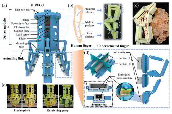
Figure 1.
Structural design of underactuated rigid–flexible coupling mechanical gripper (U-RFCG) and manufacturing process of soft structure. (a) Overall structure of U-RFCG. (b) Design concept of underactuated finger. (c) Optical images of underactuated finger conform to irregular object. (d) Structure of underactuated finger. (I) Longitudinal section view of phalanx. (II) Transverse section view of phalanx. (e) Optical images of two grasping types of precise pinch and enveloping grasp.
As shown in Figure 1b, each finger of the U-RFCG consists of a rigid segment and a flexible segment. The rigid part adopts a three-segment underactuated linkage structure inspired by the anatomy of the human finger. Specifically, the rigid segment is divided into three sequentially connected sections corresponding to the proximal, middle, and distal phalanges of a human finger. This bio-inspired design allows the finger to autonomously adjust its posture upon contact with a target object. During grasping, the underactuated mechanism enables the phalanges to adaptively envelop the contour of objects, while the flexible structure attached to the rigid phalanges prevents direct collision and ensures conformal surface contact. This design enhances the compliance of the gripper through the passive adaptability of the underactuated rigid linkage, while the flexible contact interface composed of soft materials disperses contact forces through elastic deformation, preventing localized stress concentration and thereby protecting fragile objects from damage. As shown in Figure 1c, when grasping an irregularly shaped stone, the underactuated mechanism and the flexible cavity work synergistically to conform to its rugged surface. The underactuated structure, through linkage transmission, guides each phalanx to self-adjust joint angle for conducting gripping movements, allowing the finger contours to initially align with the stone’s protrusions and recesses. The flexible cavity then undergoes adaptive deformation, filling the micro-gaps between the phalanges and the stone surface to achieve tight conformity. As shown in Figure 1d, to further improve adaptability and interactive safety, a cavity structure and an embedded microstructure are innovatively incorporated into the flexible part of each finger. The internal cavity within the flexible structure provides the necessary space for compensatory deformation upon contact. This deformability allows the flexible segment to conform to the surface of the object during grasping, distributing contact pressure and thereby better protecting the object from damage. The embedded microstructure, made of high-toughness polymer material, is distributed at the interface between the rigid phalanges and the flexible segment, firmly coupling the two structures despite their significantly different mechanical moduli.
Benefiting from the dexterous underactuated structure, the U-RFCG is empowered with two universal grasping modes, precise pinching and envelope grasping, to handle objects of varying sizes and shapes, as illustrated in Figure 1e. Pinch grasping is primarily effective for small, lightweight objects such as fresh strawberries or small bread rolls. In this mode, only the distal phalanges come into contact with the object, mimicking the “pinching” action of human fingers. In contrast, envelope grasping is designed for large or irregularly shaped objects, such as irregularly stacked instant noodle boxes or loosely structured cauliflower heads. When this mode is activated, the gripper first adjusts the initial angles of the three fingers via the drive module to surround the target object from multiple directions. As the fingers approach the object, the underactuated linkage drives the proximal, middle, and distal phalanges to rotate at different angles according to the contour of the object. Simultaneously, the flexible segments deform upon contact, filling gaps between the rigid phalanges and the object surface. This multi-segmented structure, with its multi-point conforming mechanism, fully restrains the target object. Thus, it effectively prevents the grasped object from slipping or tilting during grasping, and enables stable handling even for complex, irregular shapes.
3.2. Design of Linkage-Based Structure of Underactuated Rigid–Flexible Coupled Finger
The underactuated rigid–flexible coupled finger employs a linkage-based actuating mechanism, which consists of the proximal phalanx, middle phalanx, and distal phalanx. When actuated, the drive module delivers torque to link AB, which subsequently transmits force through the linkage mechanism to each phalanx, eventually exerting it on the grasped object. Whether in fingertip pinching or enveloping grasping mode, the finger can effectively mimic the grasping behavior of a human finger throughout the entire interaction process.
Firstly, a static model is established to reveal the influence of structural parameters on the grasping contact force. As shown in Figure 2, the lengths of the proximal, middle, and distal phalanges are biomimetically set to 1.25:1:0.8 (45 mm, 30 mm, 24 mm, respectively), referring to the length proportions of human finger phalanges. The distances between the contact points and corresponding rotation axes during grasping are .
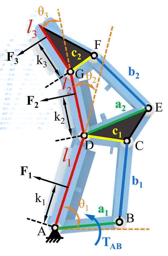
Figure 2.
Schematic diagram of the static model. Key parameters include contact force (), contact moment arm (), phalanx length (), joint rotation angle (), and linkage dimensions ().
When pinching with the fingertip, the proximal and middle phalanges remain relatively stationary. Treating the entire finger as a rigid body, we apply the principle of moment balance to derive the relationship between the fingertip contact force , , and the relative rotation angle (detailed in Text S1 and Figure S2).
Based on the theoretical model, we substitute relevant parameters for the numerical solution and obtain the results under an input torque of 1000 N·mm (Figure 3a). Clearly, the contact force exhibits a positive correlation with the angle , and it is negatively correlated with , which is a trend consistent with the behavior observed during human finger pinching. In enveloping grasping mode, each phalange adaptively conforms to the shape of target. According to the principle of virtual work () [34], we can obtain the variation in contact force:
where are expressions related to parameters (detailed in Text S2 and Figure S2). Furthermore, to ensure accuracy and stability during grasping, we optimize the dimensions of the linkages with objective functions: and . We aim to maximize the total contact force while minimizing the differences in contact forces among the phalanges. Subsequently, a multi-objective genetic algorithm is utilized for solving. We select the optimal design parameters from the resulting Pareto front, which represents a collection of non-dominated solutions, by summing the values of two optimization objectives, sorting them in descending order, and taking the median value to balance both performance goals. To minimize the impact of calculation error in a single optimization run, the final results are derived by averaging the outcomes from 10 independent optimization trials, followed by rounding to determine the definitive values, as summarized in Table 1. Finally, the optimal parameters of are determined as {31 mm, 38 mm, 20 mm, 32 mm, 35 mm, 13 mm}. Based on this, we conduct a numerical simulation of the contact force model under full enveloping conditions. The results (Figure 3b–d) demonstrate a sequential decrease in contact force from the proximal to the distal phalanx, which is a distribution pattern consistent with the biomechanical behavior observed in human finger grasping.
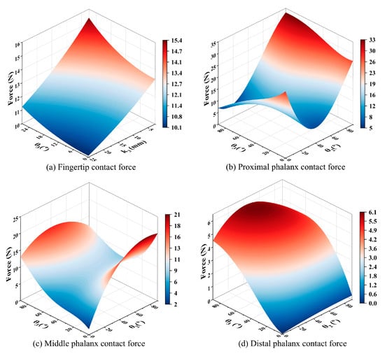
Figure 3.
Theoretical variation in the contact force. (a) Variation in contact force in fingertip pinching mode. (b) Variation in contact force across the proximal phalange in full enveloping grasping mode. (c) Variation in contact force across the middle phalange in full enveloping grasping mode. (d) Variation in contact force across the distal phalange in full enveloping grasping mode.

Table 1.
The multi-objective optimization results obtained ten times via the MATLAB Genetic Algorithm Toolbox, along with their average values and rounded results.
Kinematically, the underactuated finger is powered by a single actuation element. Based on the parameter set and linkage dimensions, a well-defined kinematic model can be established. Figure 4 shows the entire process of the underactuated finger achieving enveloping contact. The rotation axis A on the proximal phalanx is fixed to the base of the actuation module. And the connecting link PB, actuated by the motor, undergoes displacement and transmits motion through the linkage mechanism. Since the underactuated structure has more than one degree of freedom, the motion of the mechanism is indeterminate. Therefore, to accurately analyze the kinematic characteristics of the finger, we divided the entire process into three stages. In phase I, all phalanges rotate together around rotation axis A following , with the entire finger functioning as a slider–rocker mechanism. After the proximal phalanx contacts the object, phase II begins. The proximal phalanx is fixed, and the middle and distal phalanges rotate together around rotation axis D, with the finger becoming a combination of a slider–rocker and a double-rocker mechanism. In phase III, once the middle phalanx contacts and becomes fixed relative to the object, the distal phalanx rotates independently around axis G. The finger functions as a multi-linkage mechanism possessing a single degree of freedom. Upon contact of the distal phalanx with the object, the underactuated finger successfully completes the enveloping grasp. To construct a comprehensive kinematic model, a coordinate system - is defined on the lateral plane of the finger, with the fixed point A designated as the origin, in order to precisely characterize the positions of key points. To simplify the analysis, the initial position of each phalanx is aligned vertically to minimize kinematic interference from adjacent phalanges during motion.
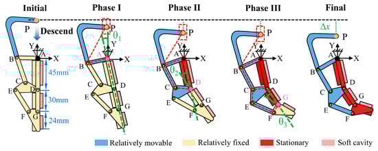
Figure 4.
Schematic of the three-phase enveloping process: from free state to proximal (phase I), middle (phase II), and distal (phase III) phalanx contact. The red dashed line represents the simplified linkage mechanism, while the green dashed and solid lines represent the rotation angles. Key parameters include the displacement () of point P (treated as a slider on the actuated link PB), the rotation angle of the proximal phalanx relative to the vertical direction (), the relative rotation angle of the middle phalanx with respect to the proximal phalanx (), and the relative rotation angle of the distal phalanx relative to the middle phalanx ().
As shown in Figure 5, using the closed-loop vector method [35], we obtained the kinematic characteristics of the phalanges (detailed in Text S3). The results indicate a progressive increase in motion intensity from the proximal to the distal end, with the distal phalanx exhibiting significantly greater flexibility compared to the proximal and middle phalanges, which demonstrates highly biomimetic behavior. Moreover, the motion profiles of the phalanges remain continuous, showing no abrupt changes in displacement or velocity, which confirms the smooth operation of the designed underactuated finger. This stability is essential for achieving reliable and precise grasping performance in robotic applications.
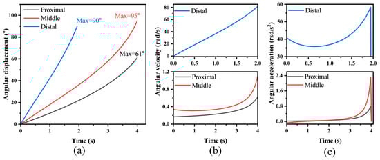
Figure 5.
Kinematic characteristics of the underactuated finger. (a) Angular displacement curves. (b) Angular velocity curves. (c) Angular acceleration curves.
3.3. Investigation of Microstructure Toughening Mechanism
The interface between the rigid skeleton and the flexible cavity is critical in rigid–flexible coupling design. However, the significant mismatch of elastic modulus between the two distinct materials presents a challenge for firm connection. Since the elastic modulus of the rigid skeleton is significantly higher than that of the flexible cavity, a substantial discrepancy in their deformation capacities arises when the structure is subjected to external forces. Specifically, the rigid material exhibits minimal deformation, whereas the flexible material is prone to significant deformation. This deformation incompatibility directly induces the occurrence of stress concentration at the interfacial junction. Over time, the prolonged action of external forces leads to the continuous accumulation of concentrated stress, which ultimately impairs the interfacial bonding strength and triggers problems such as interfacial delamination. Consequently, the connection between the rigid skeleton and the flexible cavity fails, resulting in a significant reduction in the stability and reliability of the rigid–flexible coupling structure.
The rigid–flexible coupling mechanism of the human finger offers valuable inspiration for addressing the aforementioned challenges. As shown in Figure 6a, in the structure of the human finger, the rigid bones and flexible skin achieve efficient and stable coupling through unique connecting units known as fibrous septa. Specifically, the phalanges possess a relatively high elastic modulus, while the outer wrapping skin is soft and deformable, with a modulus much lower than that of the phalanges. Between these two structures with significantly different properties, dense fibrous septa extend radially from the outer surface of the phalanges to the skin, forming a robust connection system. Emulating this natural solution, we introduced a micropillar array to serve as an intermediate layer between the rigid skeleton and the flexible cavity. As shown in Figure 6b, the micropillars, monolithically integrated with the flexible cavity, are fully embedded into the rigid substrate, thereby ensuring a firm anchor. This type of connection can effectively disperse the stress generated by the deformation difference between the two components, prevent excessive stress concentration at the interface, and thereby avoid the occurrence of slippage or even detachment.
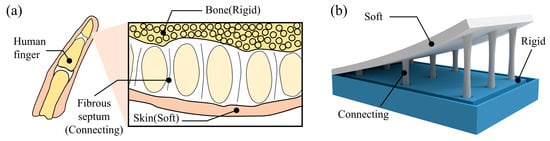
Figure 6.
Investigation of bionic principle for rigid–flexible coupling. (a) Rigid–flexible coupling connection mechanism of human finger. (b) Structure of rigid skeleton and flexible component connected via embedded micropillar coupling, inspired by human finger structure.
The dimensional parameters of the micropillar structure significantly impact its mechanical properties. Therefore, we performed tests on samples with varying structures using a tensile apparatus (Figure S4) to identify the optimal structural dimensions that satisfy the coupling criteria of the rigid framework and the flexible component. As shown in Figure 7a, we systematically investigated the tensile force response behavior of the structure under different tensile displacements with the core dimensional parameters of the micropillar structure, including diameter, height, and array density. To precisely capture differences in mechanical responses across distinct deformation stages, the tensile distance was set to range from 2 mm to 10 mm, with an equal interval of 2 mm. Meanwhile, the array density was configured into three typical layouts, including 1 × 1, 2 × 2, and 3 × 3, to quantify how density variations affect the overall tensile performance of the micropillar array (Figure S5). The results indicate that under the same tensile displacement, the tensile force increases with both the enlargement of the micropillar diameter D (Figure 7b) and the increase in the number of micropillars in the array (Figure S6). This phenomenon can be attributed to the expanded load-bearing cross-sectional area of individual micropillars and the superimposed load-bearing effect of multiple micropillars.
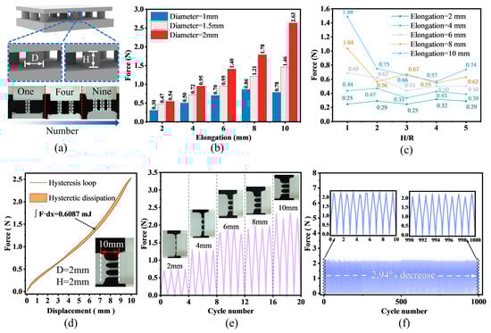
Figure 7.
Performance of the micropillar structure. (a) Schematic diagram of key dimensional parameters of the micropillar structure, including diameter D, height H, and array quantity. (b) The influence of the diameter on the tensile force under different tensile distances, where the diameters include three sizes: 1 mm, 1.5 mm, and 2 mm. (c) The influence of the aspect ratio (H/R) on the tensile force under different tensile distances, where the aspect ratios include five values ranging from 1 to 5. (d) The hysteresis loop of a single loading–unloading cycle for the micropillar structure (D = 2 mm, H = 2 mm) under a 10 mm tensile distance. (e) Cyclic loading results under different tensile distances. (f) Fatigue test results of 1000 cyclic loadings under a 10 mm tensile distance.
Furthermore, to characterize the coupling effect of diameter and height and avoid limitations from focusing on a single parameter, we explored the influence of aspect ratio (H/R) on performance. As shown in Figure 7c, when the tensile displacement is 2 mm, the difference in tensile force among varying H/R values is minimal. However, as the tensile displacement gradually increases, the discrepancy in tensile force under differing H/R conditions becomes more pronounced, with an overall trend of decreasing tensile force as H/R increases. It follows that micropillars with a smaller H/R exhibit higher rigidity, which enables them to demonstrate superior resistance to deformation under stress and effectively prevent slippage at the rigid–flexible coupling interface. By synthesizing the test results and adapting them to the actual dimensions of the rigid framework, the optimal parameters for the micropillar structure were finally determined: a micropillar diameter of 2 mm, a height of 2 mm, and an array density arranged in a 3 × 3 configuration. This design not only guarantees the stability of the rigid–flexible coupling interface under stress but also precisely aligns with the dimensional requirements for integration into the rigid structure.
Additionally, a comprehensive validation of the relevant properties of the determined micropillar structure was conducted. Firstly, we characterized the variation in tensile force during the “loading–unloading” process of the micropillar structure under a 10 mm tensile distance, with the results shown in Figure 7d. Obviously, the mechanical behavior of the micropillar structure differs between the stretching stage and the recovery stage, exhibiting hysteretic characteristics. By calculating the area of the hysteresis loop, we found that the energy consumed by the micropillar structure in one “loading–unloading” cycle is 0.6087 mJ. This indicates that the micropillar structure has a certain energy dissipation capacity. In addition, durability constitutes a critical performance metric for practical applications. As illustrated in Figure 7e, under small tensile displacements (2 mm and 4 mm), the tensile force stabilizes at approximately 0.75 N and 1.25 N, respectively. Nevertheless, with an increase in tensile displacement, the stability of the tensile force gradually diminishes, accompanied by a consistent elevation in peak force. Morphological observations of the micropillar structure reveal that severe deformation occurs under large displacements, which implies a potential compromise in its fatigue life during prolonged service. Consequently, we conducted 100 cyclic loading–unloading experiments on the micropillar structure at a tensile distance of 10 mm. The results indicated an attenuation rate of only 2.94% (Figure 7f), demonstrating that the micropillar structure possesses commendable durability.
3.4. Performance Characterization of the Underactuated Finger
Uniform contact force distribution during object grasping represents a critical feature of underactuated rigid–flexible coupled fingers. This characteristic not only substantially influences the grasping stability of the gripper system but also effectively mitigates localized stress concentration when manipulating deformable or fragile objects, thereby preventing potential damage induced by excessive force exertion from individual finger segments. To quantitatively evaluate this property, we conducted experimental measurements simulating realistic object-contact scenarios. As illustrated in Figure 8a, the experimental configuration involved a dynamometer fixed at a predetermined position to establish contact with the finger mechanism when the three phalanges were vertically aligned. The driving slider was programmed to descend at a constant velocity of 2 mm/s while recording the corresponding force data (the experimental setup is detailed in Supplementary Figure S7). Sequential measurements of contact forces were performed for the proximal, medial, and distal phalanges, with results presented in Figure 8b. Across 18 complete contact–separation cycles, the recorded mean peak contact forces for each phalanx were 3.58 N, 3.66 N, and 3.5 N, respectively. All phalanges exhibited low variability in contact force measurements, with coefficients of variation not exceeding 5.2%. The proximal, middle, and distal phalanges achieved values of 4.3%, 5.1%, and 3.8%, respectively, indicating highly consistent and reliable experimental data. Meanwhile, this narrow force distribution confirms highly consistent force output characteristics among different phalanges during contact events. Furthermore, the force profiles exhibited remarkable stability throughout cyclic testing, devoid of anomalous fluctuations, which substantiates predictable and controllable force transmission behavior during finger–object interaction.
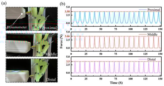
Figure 8.
(a) Schematic diagram of the contact force testing principle. (b) Test results of repeated contact force measurements on each knuckle when the driving slider descends by the same distance.
Notably, we found that the force variation curve of the proximal phalange is significantly smoother than those of the middle and distal phalanges throughout each cycle. This observation confirms an excellent buffering effect of the proximal phalange. As shown in Figure 9a, in the enveloping grasping mode, the soft components of all phalanges gradually deform as contact progresses. The proximal phalange, which makes initial contact with the object, experiences a longer duration of contact. This extension allows the soft component of the proximal phalange sufficient space for deformation, enabling it to dissipate instantaneous forces effectively. Consequently, this results in a more stable force output curve. This buffering characteristic significantly mitigates the instantaneous peak of contact force during grasping and reduces the risk of cracks or fragmentation in fragile targets caused by localized stress concentrations. Thus, it enhances the applicability and operational safety of the mechanical gripper when handling brittle materials. To further validate this, we randomly selected one cycle from force variation data of each phalange for analysis. As shown in Figure 9b, the force variation curves of all phalanges exhibit gentle variation with minimal fluctuations. This indicates that the flexible components of each phalanx provide buffering. Among these, the buffering effect of the proximal phalange is particularly pronounced, and this aligns with previous findings that greater deformation in the proximal phalange enhances buffering capacity of this phalange. A deeper comparison of contact-phase force changes reveals that contact forces of the three phalanges differ only slightly at each sampling point, and they remain nearly consistent overall. This underscores that the gripper achieves a uniform force distribution via inter-phalange synergistic interaction in enveloping grasping, which effectively prevents excessive force concentration on any single phalange.
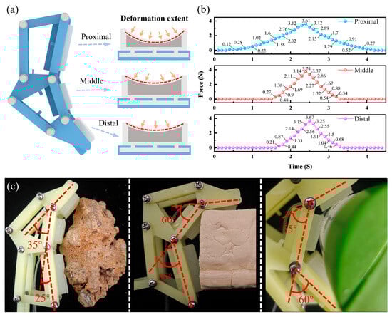
Figure 9.
(a) Schematic diagram of varying degrees of deformation of each knuckle upon contact. (b) Test results of force variation in different knuckles during single-contact process. (c) Enveloping condition of underactuated finger on objects of different shapes, including irregular stones, square tofu, and cylindrical bottles.
To investigate the adaptability of a single finger to different object surfaces, we conducted experiments in which the finger was brought into contact with objects of varying shapes. During the tests, we observed both the morphological changes in the finger and its enveloping effect on the objects. As illustrated in Figure S8, three representative object types were selected for evaluating the finger’s adaptive performance: irregular stones, 40 mm × 60 mm tofu blocks (regular square shape), and cylindrical bottles with a 50 mm diameter (regular circular shape). The results, presented in Figure 9c, show that when interacting with a rock with a rugged surface, the underactuated structure adjusts the joint angles to 25° and 35°, allowing the flexible component to fit into the rock’s grooves and protrusions for a tight enclosure. For the regular square tofu blocks and cylindrical bottles, the underactuated structure modifies the joint angles appropriately to match the square edges and cylindrical curvature, respectively, ensuring effective contact with the object surfaces.
In summary, whether the target object is an irregular stone, a square tofu block, or a cylindrical bottle, the underactuated structure works in conjunction with the flexible components to achieve optimal surface fitting by precisely adjusting the angles. This fully demonstrates the excellent adaptability enabled by the synergy between the underactuated structure and flexible components.
3.5. Grasping Performance of U-RFCG
The U-RFCG was successfully integrated into a three-dimensional motion platform to demonstrate its universal grasping performance. As illustrated in Figure 10a, the drive system of the platform comprises motors and linear guides distributed along the X, Y, and Z axes, enabling precise linear movement of the gripper in all directions and facilitating accurate positioning at designated working locations. This system has demonstrated effectiveness in executing various fruit grasping tasks. As shown in Figure 10b, the target objects exhibit diverse physical characteristics, including irregularly shaped cauliflower, fragile instant noodles, soft tofu, and heavy cabbage, thereby highlighting the strong adaptive grasping capability of U-RFCG.
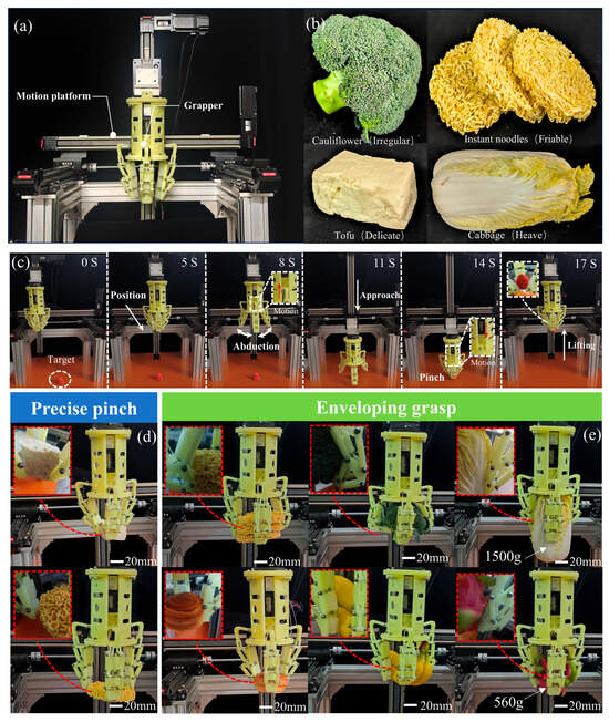
Figure 10.
Grasp experiment with diverse objects. (a) A three-dimensional motion platform carrying a rigid–flexible coupling gripper for positional delivery. (b) Representative test objects, including irregularly shaped cabbages, fragile fried noodles, tender tofu, and heavy cabbage. (c) The complete working process of the gripper in pinch mode, where it delivers the strawberries to a certain height. The red arrows indicate the direction of movement of the slider. The overall process includes reaching the target position, then grasping the strawberries, and finally lifting them to 30 cm. (d) Examples and detailed descriptions of the gripper precisely pinching tofu and fried instant noodles. (e) Operation in enveloping grasp mode and contact details. Tested objects are categorized by their challenges: fragile (e.g., bread, noodles), irregularly shaped (e.g., broccoli, banana), and heavy (e.g., 1500 g cabbage, 560 g dragon fruit).
For small-sized objects, the gripper employs a pinching mode, utilizing its distal phalanges to securely grasp items. Importantly, the incorporation of flexible materials increases the contact area and distributes localized pressure, minimizing surface damage during the grasping process. Strawberries, representative of small and delicate objects, have a skin thickness ranging from 0.2 to 0.5 mm, rendering them highly susceptible to mechanical injury. Achieving non-destructive grasping of strawberries presents a significant challenge for robotic manipulation. Therefore, precise control of end-effector contact force is essential during the pinching process. As depicted in Figure 10c, the process of the gripper grasping a strawberry precisely in pinching mode is demonstrated. The motor-controlled three-dimensional motion platform first positions the gripper at the target location. Subsequently, the precision lead screw mechanism within the drive module actuates the three underactuated fingers to open synchronously. Upon descent to the target point via z-axis motor control, the internal drive module initiates finger closure toward the center until the distal phalanges make contact with the object, completing the pinch grasp—effectively mimicking human fingertip grasping behavior. Notably, post-grasping inspection revealed no damage to the strawberry skin, attributable to the protective function of the flexible air cavity.
To further evaluate performance in pinching mode, more challenging objects were tested. As shown in Figure 10d, tests were conducted on tofu and extremely fragile fried instant noodles. Unlike strawberries, which possess a protective outer layer, tofu is fully exposed and prone to deformation or fracture during handling; additionally, its relatively high mass necessitates sufficient clamping force for stable grasping. Fried instant noodles, by contrast, are highly sensitive to external pressure. These conditions demand precise modulation of contact forces to prevent damage. Significantly, the U-RFCG successfully lifted both tofu and fried instant noodles from their initial positions to a height of 30 cm and transported them horizontally at this elevation (Video S1), with no observable damage incurred. These results indicate that the gripper can apply appropriate contact forces in pinching mode, ensuring safe and stable handling of fragile and vulnerable objects.
For large or complex-shaped objects, the gripper operates in enveloping mode. As illustrated in Figure 10e, enveloping grasping experiments were conducted on objects with varying morphological features. These included a stack of three fried instant noodles—more voluminous and structurally complex than single-layer counterparts—and a surface-crispy bread. In both cases, the U-RFCG achieved successful grasping without causing fragmentation or structural damage. To further assess enveloping capability, we conducted tests on a variety of irregularly shaped fruits and vegetables (Video S2). Results show that when interacting with clustered cauliflower or elongated bananas, each phalanx made contact with the object surface, and the fingers adaptively conformed to the contours, achieving complete envelopment. Furthermore, to assess the load-bearing capacity of the gripper, which is a critical performance metric, we evaluated the gripper by having it grasp a 1500 g cabbage and a 560 g pitaya (Video S3). The U-RFCG is able to firmly grasp and smoothly transport both items. Crucially, after completion of the grasping task, the flexible components on the underactuated fingers securely attached to the rigid structure without slippage or delamination, even under substantial load. This demonstrates not only the high load tolerance of the gripper but also the effectiveness of embedded microstructure in robustly coupling materials with significantly different elastic moduli. Moreover, all the grasping actions are driven by a single motor, which indicates that U-RFCG features a simplified control system and a versatile structure.
In summary, the U-RFCG exhibits outstanding performance in both pinching and enveloping modes. The integration of flexible elements effectively protects grasped objects, with no damage observed across all test scenarios. The rigid structure provides excellent adaptability and load-bearing capacity, while the flexible microstructure functions reliably as an interfacial coupling agent, ensuring stable integration between rigid and soft components. These outcomes align closely with the original design objectives.
4. Conclusions
In summary, this work develops an underactuated rigid–flexible coupled gripper inspired by the hybrid structure of human fingers, with its key innovation concentrating on an embedded microstructure that integrates a rigid skeleton (for strength and drive transmission) and soft tissues (for buffering and conformability), mimicking human finger bones and soft tissues to achieve “rigid–flexible” synergy. Validation tests demonstrate that the gripper can handle a wide range of objects, from soft and fragile items like tofu to an irregular and heavy cabbage with a weight of 1.5 kg, balancing payload capacity, dexterous manipulation, and flexible safety. Driven by a single-lead-screw motor, the gripper uses an underactuated linkage mechanism to enable multi-phalanx fingers to adaptively envelop objects, eliminating the need for multiple independent joint actuators and significantly reducing cost, weight, and control complexity. In terms of manufacturing, a microstructure casting process allows liquid silicone rubber to penetrate 3D-printed rigid porous plates, forming a mechanically interlocked structure that dissipates stress, effectively addressing traditional rigid–soft interface failure issues. Tensile tests and successful grasps of a 560 g pitaya and a 1500 g cabbage with no slippage or cracking at the interface confirmed that the interlocked structure is reliable. Contact force measurements confirmed a consistent distribution pattern across all phalanges, with recorded values of 3.58 N, 3.66 N, and 3.50 N showing limited variations (ranges of −0.15 N to 0.08 N, −0.18 N to 0.15 N, and −0.13 N to 0.17 N, respectively) during repeated tests, which uniformity demonstrates the effectiveness of the underactuated mechanism in achieving balanced force transmission. Integrated with a three-axis platform, the gripper achieves damage-free pinching of small and fragile items like strawberries and tofu, as well as stable full-envelope grasping of irregular or stacked objects, fulfilling the design goal of a universal, adaptive mechanical gripper. Compared to single-material grippers, our U-RFCG integrates the high load capacity and excellent motion characteristics of rigid grippers with the compliant contact features of soft grippers that prevent damage to grasped objects. This synergistic combination excels in applications necessitating secure grasping and exceptional manipulability.
Furthermore, the current U-RFCG is a passively adaptive gripper lacking real-time perception of object slippage or contact force magnitude. Future work will integrate flexible sensors into the flexible cavities or rigid skeleton to provide tactile perception capabilities, while incorporating machine learning approaches to enable more intelligent grasping and further enhance adaptive performance.
Supplementary Materials
The following supporting information can be downloaded at: https://www.mdpi.com/article/10.3390/machines13111068/s1, Text S1: Derivation of Fingertip Grasping Contact Force Model; Text S2: Derivation of Enveloping Contact Force Model; Text S3: Derivation of the Kinematic Model; Figure S1: Schematic diagrams of manufacturing process for soft structure; Figure S2: Schematic diagrams for contact force analysis of two grasping modes; Figure S3: Kinematic analysis of the enveloping grasp using closed-loop vector diagram; Figure S4: Optical images of the tensile testing apparatus; Figure S5: Changes in the rigid-flexible coupling interface upon the extension of micro-columns to different heights (2–10 mm in 2 mm increments); Figure S6: Bar chart of the effect of microcolumn array density on tensile force; Figure S7: Diagram of the finger contact force testing device; Figure S8: Optical images of the objects used in the single-finger conforming experiment; Video S1: The video of the gripper grabbing tofu and fried instant noodles; Video S2: The video of the gripper grabbing cauliflower and elongated banana; Video S3: The video of the gripper grabbing cabbage and pitaya.
Author Contributions
Formal analysis, H.L., Y.H. and J.L.; funding acquisition, H.L. and Y.W.; methodology, H.L. and X.H.; project administration, H.L. and Y.W.; validation, Y.C., Z.H. and S.Y.; writing—original draft, H.L.; writing—review and editing, Y.W. All authors have read and agreed to the published version of the manuscript.
Funding
This work was supported by the Graduate Innovation Special Fund Project of Jiangxi Province (Grant No. YC2025-S125) and Natural Science Foundation project of Jiangxi Province (Grant No. 20242BAB20207).
Data Availability Statement
The raw data supporting the conclusions of this article will be made available by the authors on request.
Conflicts of Interest
The authors declare no conflict of interest.
References
- Zhang, Z.-Y.; Wang, X.-D.; Ren, T.-Q.; Jin, T.-L. Novel Gripper Module and Method for Automated Assembly of Miniature Parts. Adv. Manuf. 2023, 11, 295–310. [Google Scholar] [CrossRef]
- Sun, X.; Wang, C.; Chen, W.; Chen, W.; Yang, G.; Jin, Y. A Single-Actuator Four-Finger Adaptive Gripper for Robotic Assembly. IEEE Trans. Ind. Electron. 2023, 70, 12555–12565. [Google Scholar] [CrossRef]
- Xu, J.; Wan, W.; Koyama, K.; Domae, Y.; Harada, K. Selecting and Designing Grippers for an Assembly Task in a Structured Approach. Adv. Robot. 2021, 35, 381–397. [Google Scholar] [CrossRef]
- Eom, J.; Yu, S.Y.; Kim, W.; Park, C.; Lee, K.Y.; Cho, K.-J. MOGrip: Gripper for Multiobject Grasping in Pick-and-Place Tasks Using Translational Movements of Fingers. Sci. Robot. 2024, 9, eado3939. [Google Scholar] [CrossRef]
- Iqbal, Z.; Pozzi, M.; Prattichizzo, D.; Salvietti, G. Detachable Robotic Grippers for Human-Robot Collaboration. Front. Robot. AI 2021, 8, 644532. [Google Scholar] [CrossRef]
- Salvietti, G.; Iqbal, Z.; Hussain, I.; Prattichizzo, D.; Malvezzi, M. The Co-Gripper: A Wireless Cooperative Gripper for Safe Human Robot Interaction. In Proceedings of the 2018 IEEE/RSJ International Conference on Intelligent Robots and Systems (IROS), Madrid, Spain, 1–5 October 2018; pp. 4576–4581. [Google Scholar]
- Ruiz-Ruiz, F.J.; Ventura, J.; Urdiales, C.; Gómez-de-Gabriel, J.M. Compliant Gripper with Force Estimation for Physical Human–Robot Interaction. Mech. Mach. Theory 2022, 178, 105062. [Google Scholar] [CrossRef]
- Yoder, Z.; Macari, D.; Kleinwaks, G.; Schmidt, I.; Acome, E.; Keplinger, C. A Soft, Fast and Versatile Electrohydraulic Gripper with Capacitive Object Size Detection. Adv. Funct. Mater. 2023, 33, 2209080. [Google Scholar] [CrossRef]
- Tawk, C.; Alici, G. A Review of 3D—Printable Soft Pneumatic Actuators and Sensors: Research Challenges and Opportunities. Adv. Intell. Syst. 2021, 3, 2000223. [Google Scholar] [CrossRef]
- Reddy, P.V.P.; Suresh, V.V.N.S. A review on importance of universal gripper in industrial robot applications. Int. J. Mech. Eng. Robot. Res. 2013, 2, 256–264. [Google Scholar]
- Acar, O.; Sağlam, H.; Şaka, Z. Evaluation of Grasp Capability of a Gripper Driven by Optimal Spherical Mechanism. Mech. Mach. Theory 2021, 166, 104486. [Google Scholar] [CrossRef]
- Acar, O.; Sağlam, H.; Şaka, Z. Measuring Curvature of Trajectory Traced by Coupler of an Optimal Four-Link Spherical Mechanism. Measurement 2021, 176, 109189. [Google Scholar] [CrossRef]
- Li, H.; Zhou, P.; Zhang, S.; Yao, J.; Zhao, Y. A High-Load Bioinspired Soft Gripper with Force Booster Fingers. Mech. Mach. Theory 2022, 177, 105048. [Google Scholar] [CrossRef]
- Yap, H.K.; Ng, H.Y.; Yeow, C.-H. High-Force Soft Printable Pneumatics for Soft Robotic Applications. Soft Robot. 2016, 3, 144–158. [Google Scholar] [CrossRef]
- Zhang, N.; Zhou, P.; Yang, X.; Shen, F.; Ren, J.; Hou, T.; Dong, L.; Bian, R.; Wang, D.; Gu, G.; et al. Biomimetic Rigid-Soft Finger Design for Highly Dexterous and Adaptive Robotic Hands. Sci. Adv. 2025, 11, eadu2018. [Google Scholar] [CrossRef]
- Kim, U.; Jung, D.; Jeong, H.; Park, J.; Jung, H.-M.; Cheong, J.; Choi, H.R.; Do, H.; Park, C. Integrated Linkage-Driven Dexterous Anthropomorphic Robotic Hand. Nat. Commun. 2021, 12, 7177. [Google Scholar] [CrossRef] [PubMed]
- Wu, Z.; Li, X.; Guo, Z. A Novel Pneumatic Soft Gripper with a Jointed Endoskeleton Structure. Chin. J. Mech. Eng. 2019, 32, 78. [Google Scholar] [CrossRef]
- Cianchetti, M.; Laschi, C.; Menciassi, A.; Dario, P. Biomedical Applications of Soft Robotics. Nat. Rev. Mater. 2018, 3, 143–153. [Google Scholar] [CrossRef]
- Dao, T.-P.; Le, H.G.; Ho, N.L. Topology-Shape-Size Optimization Design Synthesis of Compliant Grippers for Robotics: A Comprehensive Review and Prospective Advances. Rob. Auton. Syst. 2025, 193, 105106. [Google Scholar] [CrossRef]
- Zhou, X.; Fu, H.; Shentu, B.; Wang, W.; Cai, S.; Bao, G. Design and Control of a Tendon-Driven Robotic Finger Based on Grasping Task Analysis. Biomimetics 2024, 9, 370. [Google Scholar] [CrossRef] [PubMed]
- Tawk, C.; Gillett, A.; Het Panhuis, M.; Spinks, G.M.; Alici, G. A 3D-Printed Omni-Purpose Soft Gripper. IEEE Trans. Robot. 2019, 35, 1268–1275. [Google Scholar] [CrossRef]
- Lee, K.; Wang, Y.; Zheng, C. TWISTER Hand: Underactuated Robotic Gripper Inspired by Origami Twisted Tower. IEEE Trans. Robot. 2020, 36, 488–500. [Google Scholar] [CrossRef]
- Subramaniam, V.; Jain, S.; Agarwal, J.; Valdivia, Y.; Alvarado, P. Design and Characterization of a Hybrid Soft Gripper with Active Palm Pose Control. Int. J. Robot. Res. 2020, 39, 1668–1685. [Google Scholar] [CrossRef]
- Manti, M.; Hassan, T.; Passetti, G.; D’Elia, N.; Laschi, C.; Cianchetti, M. A Bioinspired Soft Robotic Gripper for Adaptable and Effective Grasping. Soft Robot. 2015, 2, 107–116. [Google Scholar] [CrossRef]
- Zhang, C.; Zhang, Z.; Peng, Y.; Zhang, Y.; An, S.; Wang, Y.; Zhai, Z.; Xu, Y.; Jiang, H. Plug & Play Origami Modules with All-Purpose Deformation Modes. Nat. Commun. 2023, 14, 4329. [Google Scholar] [CrossRef]
- Yang, H.; Zhang, C.; Xu, Y. A Mortise-Tenon Inspired Variable Stiffness Finger for Multi-Mode Grasping. Sens. Actuators A Phys. 2025, 382, 116108. [Google Scholar] [CrossRef]
- Zhou, P.; Zhang, N.; Gu, G. A Biomimetic Soft—Rigid Hybrid Finger with Autonomous Lateral Stiffness Enhancement. Adv. Intell. Syst. 2022, 4, 2200170. [Google Scholar] [CrossRef]
- Zhu, J.; Chai, Z.; Yong, H.; Xu, Y.; Guo, C.; Ding, H.; Wu, Z. Bioinspired Multimodal Multipose Hybrid Fingers for Wide-Range Force, Compliant, and Stable Grasping. Soft Robot. 2023, 10, 30–39. [Google Scholar] [CrossRef] [PubMed]
- Deimel, R.; Brock, O. A novel type of compliant and underactuated robotic hand for dexterous grasping. Int. J. Robot. Res. 2016, 35, 161–185. [Google Scholar] [CrossRef]
- Fu, H.C.; Ho, J.D.; Lee, K.H.; Hu, Y.C.; Au, S.K.; Cho, K.J.; Sze, K.Y.; Kwok, K.W. Interfacing soft and hard: A spring reinforced actuator. Soft Robot. 2020, 7, 44–58. [Google Scholar] [CrossRef]
- Guo, X.Y.; Li, W.B.; Gao, Q.H.; Yan, H.; Fei, Y.Q.; Zhang, W.M. Self-locking mechanism for variable stiffness rigid-soft gripper. Smart Mater. Struct. 2020, 29, 35033. [Google Scholar] [CrossRef]
- Su, C.; Wang, R.; Lu, T.; Wang, S. SAU-RFC hand: A novel self-adaptive underactuated robot hand with rigid-flexible coupling fingers. Robotica 2022, 41, 511–529. [Google Scholar] [CrossRef]
- Tang, Y.; Chi, Y.; Sun, J.; Huang, T.H.; Maghsoudi, O.H.; Spence, A.; Zhao, J.; Su, H.; Yin, J. Leveraging elastic instabilities for amplified performance: Spine-inspired high-speed and high-force soft robots. Sci. Adv. 2020, 6, eaaz6912. [Google Scholar] [CrossRef] [PubMed]
- Birglen, L.; Gosselin, C.M. Kinetostatic Analysis of Underactuated Fingers. IEEE Trans. Robot. Automat. 2004, 20, 211–221. [Google Scholar] [CrossRef]
- Wampler, C.W. Solving the Kinematics of Planar Mechanisms. J. Mech. Des. 1999, 121, 387–391. [Google Scholar] [CrossRef]
Disclaimer/Publisher’s Note: The statements, opinions and data contained in all publications are solely those of the individual author(s) and contributor(s) and not of MDPI and/or the editor(s). MDPI and/or the editor(s) disclaim responsibility for any injury to people or property resulting from any ideas, methods, instructions or products referred to in the content. |
© 2025 by the authors. Licensee MDPI, Basel, Switzerland. This article is an open access article distributed under the terms and conditions of the Creative Commons Attribution (CC BY) license (https://creativecommons.org/licenses/by/4.0/).