Abstract
Soft robots often suffer from insufficient load capacity due to the softness of their materials. Existing variable stiffness technologies usually introduce rigid components, resulting in decreased flexibility and complex structures of soft robots. To address these challenges, this work proposes a novel wrist-gripper composite soft end-effector based on the weaving jamming principle, which features a highly integrated design combining structure, actuation, and stiffness. This end-effector is directly woven from pneumatic artificial muscles through weaving technology, which has notable advantages such as high integration, strong performance designability, lightweight construction, and high power density, effectively reconciling the technical trade-off between compliance and load capacity. Experimental results demonstrate that the proposed end-effector exhibits excellent flexibility and multi-degree-of-freedom grasping capabilities. Its variable stiffness function enhances its ability to resist external interference by 4.77 times, and its grasping force has increased by 1.7 times, with a maximum grasping force of 102 N. Further, a grasping force model for this fiber-reinforced woven structure is established, providing a solution to the modeling challenge of highly coupled structures. A comparison between theoretical and experimental data indicates that the modeling error does not exceed 7.8 N. This work offers a new approach for the design and analysis of high-performance, highly integrated soft end-effectors, with broad application prospects in unstructured environment operations, non-cooperative target grasping, and human–robot collaboration.
1. Introduction
Soft robots enable more compliant, dexterous, and safer interactions with the external environment, offering significant technical advantages in complex environmental movements, flexible grasping and manipulation, and human–computer interaction. Among these, soft robotic arms and soft grippers are the most widely and classically applied, with uses spanning many fields such as disaster relief [1], minimally invasive surgery [2,3,4,5], space inspection [6,7], and nuclear fusion vessel maintenance [8]. Although soft robotic arms and grippers, primarily composed of soft materials, exhibit high flexibility, they generally suffer from low load-bearing capacity. To develop high-performance operational systems, it is essential to enhance and control the stiffness of soft robots, thereby balancing the technical trade-off between compliance and load capacity.
Currently, reinforced variable-stiffness soft robots usually require the incorporation of many rigid components and various flexible structures in the manufacturing process, resulting in complex manufacturing processes. Moreover, the introduction of numerous rigid components tends to reduce the compliance of soft robots. As is well known, existing variable-stiffness technologies mainly include particle jamming [9,10,11], layer jamming [12,13,14,15], tube jamming [16], actuation coupling [17,18], solid–liquid transition [19], and smart materials [20]. In the field of soft robotics, there is an urgent need to achieve a highly integrated design of structure, actuation, and stiffness. However, researchers seem to have overlooked the fact that weaving jamming is also an effective approach to achieving variable stiffness. Additionally, weaving a fiber shell around soft actuators can serve a reinforcing purpose. Xing et al. [21] wove silk muscles into an intelligent wearable textile actuator that enables sleeve extension and contraction under different humidity conditions. Lugger et al. [22] developed a triple-helical twisted rope constructed from individual rotating fibers, which can produce up to three times the rotational and longitudinal force, enabling it to perform tasks such as reversibly opening and lifting a screw-cap vial. Weichart et al. [23] proposed a weaving technique to integrate a micro-electromechanical systems sensing skin with a 144-sensor tactile array onto a soft, human-sized artificial fingertip, creating an artificial sensing finger with similar softness to human fingers. Therefore, weaving technology represents a highly advanced and advantageous approach in the current field of soft robot manufacturing. It is not merely a change in fabrication methods but also embodies a design philosophy of “integrated structure and function.”
This work presents a variable-stiffness wrist-gripper composite soft end-effector directly woven from fiber-reinforced pneumatic artificial muscles. The proposed soft end-effector demonstrates three key advantages: (1) high degree of structural-functional integration. The manufacturing process is significantly simplified, reducing potential failure points (such as air leakage or debonding) associated with adhesion or stitching processes. (2) Exceptional designability of performance and anisotropic control. By designing the weaving path, multiple motion modes, including elongation, contraction, and bending, can be integrated into a single structure. The final motion morphology of the end-effector can be “pre-programmed” into the weaving pattern, enabling the automatic generation of designed complex deformations upon inflation without requiring complex multi-chamber control systems. (3) Lightweight and high power density. The soft end-effector is extremely lightweight yet capable of generating substantial pulling or lifting forces (a typical advantage of pneumatic artificial muscles), thereby achieving remarkable power density (output power/weight). This is crucial for robots that require high maneuverability or carry their own weight for work.
However, soft robots manufactured using weaving technology also face challenges of severe structural coupling and difficulties in precise modeling. Through contact force analysis of the spiral pneumatic artificial muscle, we have achieved grasping force prediction for the soft gripper.
The main contributions of this work include (1) proposing a novel configuration of variable-stiffness wrist-gripper composite soft end-effector based on pneumatic artificial muscle weaving technology and (2) establishing a grasping force model for the fiber-reinforced complex woven grasping structure. This research provides guidance for the design and analysis of variable-stiffness soft robots with highly integrated structure and actuation.
2. Design and Fabrication
To achieve variable stiffness and multi-degree-of-freedom motion of soft end-effectors using fewer rigid connections and a simpler structure, we innovatively adopted the weaving-based fabrication technique to construct a wrist-gripper composite soft end-effector, as shown in Figure 1. It consists of two parts: a woven continuum wrist and an enclosed soft gripper. The enclosed soft gripper comprises five sets of U-shaped longitudinal pneumatic artificial muscles 1 (longitudinal PAMs 1) and a spiral pneumatic artificial muscle 1 (spiral PAM 1) woven circumferentially around these longitudinal muscles. By adjusting the air pressure in the spiral PAM 1, the gripper can perform grasping and releasing actions. Meanwhile, varying the air pressure in the longitudinal PAMs 1 enables stiffness adjustment of the soft gripper, ensuring stability during the grasping of different objects. Similarly, the woven continuum wrist is composed of three longitudinal pneumatic artificial muscles 2 (longitudinal PAMs 2) and a spiral pneumatic artificial muscle 2 (spiral PAM 2) woven around them. Adjusting the air pressure in longitudinal PAMs 2 allows multi-degree-of-freedom motion of the wrist. Furthermore, by regulating the internal air pressure of the spiral PAM 2, the stiffness of the continuum wrist can be flexibly controlled, significantly enhancing its motion stability.
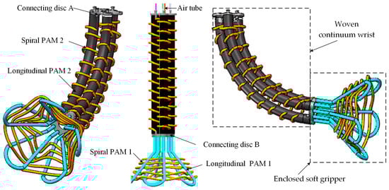
Figure 1.
Three-dimensional diagram of a multi-degree-of-freedom wrist-gripper composite end-effector with variable stiffness.
The artificial muscles of the woven continuum wrist are arranged via connecting disks A and B, which are connected to an enclosed soft gripper, collectively forming a multi-degree-of-freedom wrist-gripper composite end-effector with variable stiffness. Directly using soft actuators to construct the main structure of soft robots or continuum robots offers significant advantages: it not only reduces the reliance on rigid components and additional connectors, enhancing the flexibility and adaptability of the overall structure, but also simplifies the manufacturing process and lowers costs. In addition, existing soft robots generally suffer from weak load-bearing capacity and insufficient stiffness regulation capabilities. Introducing variable stiffness functionality often increases structural complexity. The weaving technology employed in this work ensures compliant motion of the robot while enabling active adjustment of stiffness, resulting in a more compact and highly integrated overall structure.
The multi-degree-of-freedom wrist-gripper composite soft end-effector prototype is shown in Figure 2. Connecting disks A and B were 3D-printed using UV-cured resin [Somos Imagine 8000, Dutch State Mine (DSM), Chengdu Yixuan Model Co., Ltd., Chengdu, China]. The extension and contraction motions of the woven continuum wrist are illustrated in Figure 2a, with a maximum length of 2750 mm and a minimum length of 2400 mm. The opening and closing motions of the enclosed soft gripper are shown in Figure 2b, with a diameter ranging from 122 mm to 152 mm. Figure 2c demonstrates the bending motion of the woven continuum wrist, achieving a maximum bending angle of 50°. Additionally, we conducted a soft interaction test involving both the woven continuum wrist and the enclosed soft gripper, as shown in Figure 2d, highlighting their excellent compliance. The soft gripper is capable of grasping objects of various shapes, as evidenced in Figure 2e, where it successfully secured a flat book and a cylindrical object.
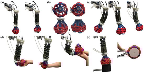
Figure 2.
The multi-degree-of-freedom woven wrist-gripper composite soft end-effector prototype. (a) Extension and contraction motion of the woven continuum wrist. (b) Cross-sectional and axonometric views of the open (left) and closed (right) states of the enclosed soft gripper. (c) Bending motion of the woven continuum wrist. (d) Soft interaction demonstration of the enclosed soft gripper. (e) Grasping of differently shaped objects by the wrist-gripper composite soft end-effector: a flat object (left) and a cylindrical object (right).
Additionally, we conducted variable stiffness tests on the prototype, as shown in Figure 3. A weight of 784 g was suspended from the tip of the woven continuum wrist, and its states with and without its PAMs being pressurized are shown in Figure 3a,b, respectively. It can be observed that pressurizing the longitudinal PAMs 2 and the spiral PAM 2 significantly enhances the stiffness of the woven continuum wrist. Figure 3c,d display the states when grasping a weight of 1000 g: with only the spiral PAM 1 of the enclosed gripper being pressurized, and with all PAMs of the enclosed gripper, as well as the woven continuum wrist being pressurized, respectively. It is evident that pressurizing the longitudinal PAMs 2 of the enclosed gripper markedly improves its stiffness and grasping stability (Supplementary Materials Video S1).
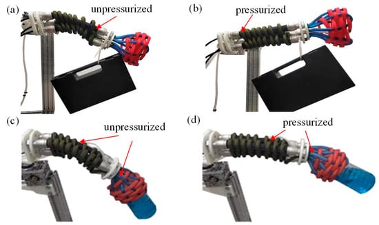
Figure 3.
Variable stiffness testing of the woven wrist-gripper composite soft end-effector. (a) State of the woven continuum wrist carrying an object when its PAMs are not pressurized. (b) State of the woven continuum wrist carrying an object when its PAMs are pressurized. (c) Grasping state of the woven continuum wrist and enclosed gripper when only spiral PAM 1 of the enclosed gripper is pressurized. (d) Grasping state of the woven continuum wrist and gripper when all PAMs are pressurized.
In addition, we conducted a multi-degree-of-freedom motion demonstration of the wrist-gripper composite soft end-effector, as shown in Figure 4 and Supplementary Materials Video S1. The wrist-gripper composite soft actuator can continuously adjust its position to follow a moving object, as depicted in Figure 4a. It can also grasp objects and achieve object transfer, as illustrated in Figure 4b. The woven continuum wrist possesses three degrees of freedom: extension and contraction, as well as rotation about two axes. The demonstration experiment confirms its flexible motion capabilities.
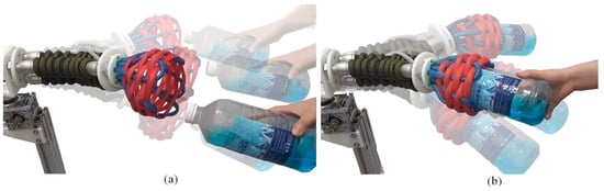
Figure 4.
Multi-DOF motion of the woven wrist-gripper composite soft end-effector. (a) Following a moving object. (b) Grasping an object and achieving object transfer.
3. Force Modeling of Enclosed Soft Gripper
3.1. Gripping Force Analysis of Enclosed Soft Gripper
The force analysis of the enclosed soft gripper is illustrated in Figure 5. It can be seen that the force equilibrium of a micro-segment sk of its spiral PAM 1 in the y-direction is expressed as
where fk and Fk represent the distributed force and the generated pulling force acting on the micro-segment of the spiral PAM 1, respectively.

Figure 5.
Force analysis diagram of the enclosed soft gripper.
According to geometric relationships, dsk can be represented as
where Rk represents the radius of the enclosed soft gripper.
Rk can be expressed as
where Rs is the radius of the inscribed circle formed by multiple longitudinal PAMs 1 at that location, while rk and tk are the inner radius and wall thickness of longitudinal PAMs 1.
Under the assumption of a small angle, it can be concluded that
where αk is the central angle corresponding to the micro-segment sk.
Substituting Equations (2) and (4) into Equation (1) yields
In order to calculate the gripping force of the soft gripper when gripping a cylinder, the spiral artificial muscle structure is divided into two parts, the +y direction part and the −y direction part, using the xz plane as the dividing plane, as shown in Figure 6. The force along the y-axis generated by the +y part is denoted as Fy+, and the force along the y-axis generated by the −y part is denoted as Fy−, with equal magnitudes on both sides. Therefore, we derive
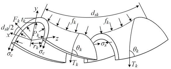
Figure 6.
Force analysis diagram of spiral artificial muscle (+y direction) of soft gripper.
From Equation (6), it can be seen that the key to calculating the gripping force of the soft gripper is to find the force Fk generated by the spiral artificial muscle.
According to Figure 6, the force balance in the x-direction can be expressed as
where Pk is the inflation pressure of the spiral PAM 1, Tk is the tension of its woven filaments, θk is the weaving angle, and σx is the stress of the elastomer along the x-direction.
Similarly, the force balance in the y-direction can be expressed as
where σc is the stress of the elastomer on the neutral plane of the spiral PAM 1, Nk is the turn number of a single woven filament near its diameter, and Lk is the length of the spiral PAM 1.
Using the small angle assumption of dαk, and then replacing dsk and fk with Equations (2) and (5), Equation (8) can be rewritten as
According to Equations (7) and (9), the driving force for the spiral PAM 1 can be derived as
The nonlinear relationship between stress and strain of PAM elastic capsules was established using the Mooney–Rivlin model. The strain energy density function of this model has the following form:
For incompressible elastic bodies, the Mooney–Rivlin function with two parameters can be expressed as
where λ1, λ2, and λ3 are the tensile ratios, and C10 and C01 are empirical constants that can be determined through uniaxial tensile testing. According to the relationship between Piola–Kirchhoff stress and Cauchy–Green strain, it can be concluded that
λ1, λ2, and λ3 can be expressed as
According to Equations (12)–(14), we can derive σc and σx as
Substituting Equation (15) into Equation (10) yields the pulling force Fk generated by the spiral artificial muscles.
3.2. Theoretical Model Verification of Gripping Force
The working pressure of the soft gripper was controlled via an electric proportional valve (ITV1030-212N, SMC Corp, Tokyo, Japan) to grip cylindrical objects of different sizes. The pull-off force values were recorded when the pressure of its spiral PAM was 0.2 MPa and compared with theoretical values, as shown in Figure 7. The theoretical pull-off force was obtained by multiplying Equation (6) by a friction coefficient of 0.35. The prototype parameters of the soft gripper are as follows: , , , , , and . It can be observed from Figure 7a that the theoretical predictions generally agree well with the experimental results, particularly when the radius of the grasped object falls within the range from 67 mm to 73 mm, where the prediction error remains within 3.2 N. However, larger prediction errors occur when gripping objects with excessively small or large diameters, as shown in Figure 7b. When the radius of the gripped target is less than 67 mm, the predicted value of the model is higher than the actual pull-off force, with a maximum error of 6.9 N. When the radius of the gripped target is greater than 73 mm, the predicted value of the model is lower than the actual pull-out force, with a maximum error of 7.8 N. Overall, the theoretical model can effectively predict the grasping force values.
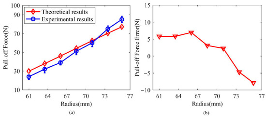
Figure 7.
The pull-off force (a) and the prediction error (b) when the soft gripper grasps objects of different sizes, with its spiral artificial muscle pressurized to 0.2 MPa.
4. Kinematics Analysis of Woven Continuum Wrist
The kinematic geometric parameters of the woven continuum wrist are shown in Figure 8. Its position is primarily determined by the lengths of its three longitudinal artificial muscles. Referring to reference [24], the inverse kinematics equations of the continuum wrist can be obtained as follows:
where l1, l2, and l3 are the lengths of the three longitudinal artificial muscles of the wrist, and rm is the radius of the circle formed by the centers of the cross-sections of the three longitudinal artificial muscles. x, y, and z are the tip coordinates of the continuum wrist, and and are the bending angle and twisting angle of the continuum wrist, respectively.
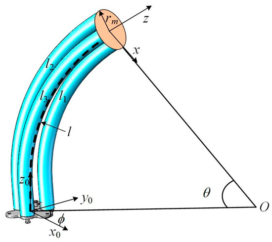
Figure 8.
Kinematic geometric diagram of the woven continuum wrist.
and can be expressed as
The forward kinematics equation of the continuum wrist is
where km is the bending curvature of the middle arc of the continuum wrist, and l is the length of the middle arc of the continuum wrist.
Geometric parameters can be represented as
5. Experimental Testing
5.1. Stiffness Testing of Enclosed Soft Gripper
We tested the changes in the gripping diameter and the center of the gripping circle of the enclosed soft gripper at different air pressures applied to its spiral PAM (with the longitudinal PAMs consistently pressurized at 0.03 MPa), as shown in Figure 9. It can be observed that as the pressure in the spiral PAM increased from 0 to 0.2 MPa, the gripping diameter decreased from 151.4 mm to 122 mm. The maximum displacement of the gripping center was 9.3 mm in the X-direction and 6.5 mm in the Y-direction.
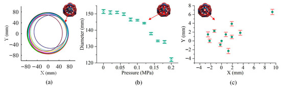
Figure 9.
The resulting variations in the grasped circular cross-section (a), diameter (b), and center position (c), when the pressure of the longitudinal PAM in the soft gripper was 0.03 MPa and the pressure of the spiral PAM was increased from 0 MPa to 0.2 MPa.
The enclosed soft gripper has variable stiffness characteristics due to its longitudinal PAMs, and we further tested its variable stiffness performance. Figure 10 shows the gripping forces exerted by the enclosed soft gripper on cylinders of different sizes and on objects of the same size but different shapes when the longitudinal PAMs were pressurized at 0 MPa and 0.2 MPa, respectively. From Figure 10a, it can be seen that as the internal pressure of the longitudinal PAMs increased, the gripping force significantly increased, with a maximum increase of 1.7 times. Figure 10b shows that the gripper exerted relatively higher gripping forces on spheres, triangular prisms, and square prisms when the longitudinal PAMs were not pressurized. However, when the longitudinal PAMs were pressurized to 0.2 MPa, the gripping forces on all object shapes increased significantly. The increments in gripping force for spheres, triangular prisms, and thin sheets reached as high as 81.25 N, 77.6 N, and 71.1 N, respectively, and its maximum gripping force can reach 102 N. Therefore, during the gripping process, increasing the air pressure in the longitudinal PAMs of the soft gripper can enhance the gripping force and improve gripping stability.
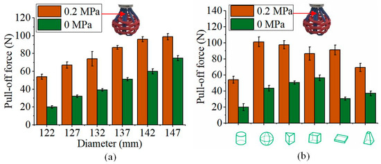
Figure 10.
A comparison of the pull-off forces exerted by the soft gripper on cylinders of different sizes (a) and on objects of different shapes but the same size (b), when the pressure in the longitudinal PAMs was increased from 0 MPa to 0.2 MPa.
5.2. Stiffness Testing of Woven Continuum Wrist
The woven continuum wrist also exhibits variable stiffness characteristics due to the presence of its longitudinal and spiral PAMs. We tested the pulling force required to displace the woven continuum wrist downward by 75 mm under two fixed pressure conditions in the longitudinal PAMs (0.1 MPa and 0.2 MPa) while gradually increasing the air pressure in its spiral PAM from 0 to 0.25 MPa, as shown in Figure 11a. The results indicate that when the pressure in the spiral PAM is constant, the pulling force increases significantly with the rise in pressure within the longitudinal PAMs. In this case, the tensile stiffness significantly increases, as shown in Figure 12a,b, with a maximum increase of 540.5 N/m, representing a substantial rise of up to 120%. Similarly, when the pressure in the longitudinal PAMs is held constant, the tensile stiffness also rises markedly with an increase in the pressure of the spiral PAM, with a maximum increase of 404.5 N/m, reaching a maximum improvement of 84%, as shown in Figure 12a,c. Therefore, increasing the internal pressure in either the longitudinal or spiral PAM of the woven continuum wrist can substantially enhance its stiffness, thereby improving operational stability.
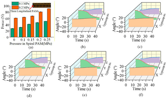
Figure 11.
(a) The pulling force required to displace the wrist downward by 75 mm under a constant pressure of 0.1 MPa or 0.2 MPa in all three longitudinal PAMs, measured while the pressure in the spiral PAM was increased from 0 to 0.25 MPa, respectively. (b–f) The variation in the wrist’s bending angle under different pressures applied to its spiral PAM, which was tested with a pressure of 0.03 MPa in two of the longitudinal muscles and a variable pressure of 0–0.4 MPa in the remaining one.
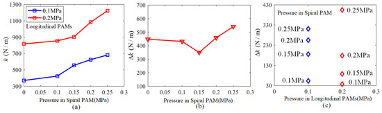
Figure 12.
(a) The tensile stiffness of the woven continuum wrist under a constant pressure of 0.1 MPa or 0.2 MPa in all three longitudinal PAMs, measured while the pressure in the spiral PAM was increased from 0 to 0.25 MPa, respectively. (b) The tensile stiffness increment of the woven continuum wrist when the air pressure of all three longitudinal PAMs increases from 0.1 MPa to 0.2 MPa, measured while the pressure in the spiral PAM was increased from 0 to 0.25 MPa, respectively. (c) The tensile stiffness increment of the woven continuum wrist when the pressure in the spiral PAM was increased from 0 to 0.25 MPa, measured while all three longitudinal PAMs are under a constant pressure of 0.1 MPa or 0.2 MPa, respectively.
Additionally, a gyroscope was installed at the tip of the continuum wrist to measure its rotational angles during motion, aiming to investigate the influence of varying the internal pressure of the spiral PAM on the wrist’s bending behavior, as illustrated in Figure 11b–f. The results show that as the internal pressure of the spiral PAM increases, the rotational angles at the tip of the continuum wrist do not change significantly, with maximum variations in only 2.17°, 3.29°, and 1.55° around the X, Y, and Z-axes, respectively. This indicates that the motion of the continuum wrist is largely unaffected by changes in the internal pressure of its spiral PAM.
Subsequently, the anti-interference capability of the woven continuum wrist was tested. The oscillations under periodic external forces applied in the direction of gravity were measured when the longitudinal PAMs were pressurized at 0.05 MPa, with the spiral PAM pressurized at 0 MPa or 0.2 MPa, respectively, as shown in Figure 13. The results demonstrate that when the spiral PAM is pressurized to 0.25 MPa, the maximum rotation angle of the tip of the continuum wrist around the X, Y, and Z-axes is reduced to merely 5.68° under the same periodic external forces in the direction of gravity (Figure 13a), representing a 4.77-fold reduction. Thus, increasing the air pressure in the spiral PAM of the continuum wrist effectively enhances its anti-interference capability.
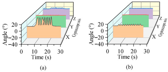
Figure 13.
The oscillation of the continuum wrist when subjected to periodic external forces in the direction of gravity. (a) The rotation angles of the tip of the continuum wrist under a periodic external force in the direction of gravity when the spiral PAM is 0 MPa and the three longitudinal PAMs are 0.05 MPa. (b) The rotation angles of the tip of the continuum wrist under a periodic external force in the direction of gravity when the spiral PAM is 0.2 MPa and the three longitudinal PAMs are 0.05 MPa.
The control logic of this woven continuum wrist adopts a serial step-by-step strategy to achieve independent adjustment of posture and stiffness, as shown in Figure 14. The specific process is as follows: (1) Posture adjustment phase: The system receives target posture commands (such as the desired bending angle and direction). The controller differentially adjusts the pressure of the three longitudinal PAMs (i.e., independently controlling the pressure of each PAM) to bring the wrist to the desired configuration. During this phase, the spiral PAM is maintained at a low baseline pressure to ensure the wrist remains sufficiently flexible for movement. (2) Stiffness locking phase: Once the wrist reaches the target posture, the system triggers the stiffness locking command. This command involves two simultaneous operations: (a) inflating the spiral PAM to raise its pressure to a preset value and (b) equalizing the internal pressure of the three longitudinal PAMs to make them identical. The contraction of the spiral PAM acts like a ‘tie strap,’ suppressing further deformation of the longitudinal PAMs through radial constraint and friction, thereby significantly enhancing the overall structural stiffness and ‘locking’ the current posture in place.
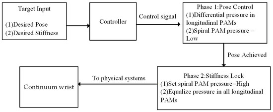
Figure 14.
Motion control logic of the woven continuum wrist.
6. Conclusions
To address the challenge of integrated actuation–structure design in soft robots, this work develops a variable-stiffness soft end-effector with a composite wrist-gripper structure, based on PAM weaving technology. The synergistic action of multiple sets of longitudinally and circumferentially arranged PAMs achieves functional integration of motion actuation and stiffness adjustment. Experimental results show that this soft end-effector exhibits good multi-degree-of-freedom motion capabilities (including extension/contraction, opening/closing, and bending) and excellent compliance, enabling adaptive grasping of objects of varying sizes and shapes. More importantly, the stiffness of the end-effector can be actively and widely modulated by adjusting the pressures in the longitudinal and spiral PAMs. It is noteworthy that the variable stiffness mechanisms for the gripper and the wrist operate on different principles. The gripper’s stiffness is primarily enhanced by pressurizing its longitudinal PAMs 1, which expand and radially press against the spiral PAM 1, thereby increasing internal friction and inducing a jamming effect. In contrast, the wrist’s stiffness is modulated through the pressurization of both its longitudinal PAMs 2 and the spiral PAM 2. When the pressure of the longitudinal PAM 1 increases from 0 MPa to 0.2 MPa, the gripping force increases up to 81.25 N, significantly enhancing grasping stability for irregularly shaped objects. The wrist’s resistance to tensile loads also improves markedly with increasing pressure in either the longitudinal or spiral PAMs, with maximum increases of 120% and 84%, respectively. The wrist’s ability to resist external disturbances is enhanced by 4.77 times, and the stiffness adjustment process barely affects its motion accuracy. Theoretically, a gripping force prediction model of the gripper was established based on force equilibrium and the Mooney–Rivlin hyperelastic model. The calculated results agree well with experimental measurements, validating the effectiveness of the structural design and force analysis. A comparison between theoretical and test results shows that the maximum prediction error is 7.8 N.
This work confirms that the proposed construction method for the composite wrist-gripper soft end-effector effectively addresses issues in traditional soft robots. Compared with existing variable stiffness technologies, including particle jamming [9,10,11], layer jamming [12,13,14,15], tube jamming [16], actuation coupling [17,18], solid–liquid transition [19], and smart materials [20], directly using soft actuators to construct the main structure of the variable-stiffness wrist-gripper composite soft actuator has significant advantages: using the weaving technology to construct the soft actuator can adjust its structural form as needed and does not require the introduction of additional parts and mechanisms to increase the variable stiffness function. It significantly improves load capacity and stability while maintaining excellent adaptability and motion flexibility, and has the advantages of low manufacturing cost, more compact structure, and lightweight design, providing new insights and a practical basis for developing high-performance, integrated soft robotic systems.
However, the developed variable-stiffness wrist-gripper composite soft actuator also has some limitations. The most notable is its relatively high operating pressure, which restricts its application in untethered scenarios, such as cooperative operation with drones. In future work, we aim to develop thinner and more efficient flexible end-effectors for weaving the robot’s structure, for instance, by utilizing film structures as the sealing layer for the PAMs. Furthermore, it should be noted that during the cyclic loading of the pneumatic actuation system, hysteresis in stiffness variation occurs. This hysteresis may stem from factors such as the viscoelastic behavior of elastic materials, internal friction within the system, and the switching characteristics of solenoid valves. Although the focus of this study is on validating the fundamental principles of adjustable stiffness and its static performance, quantitative characterization of hysteresis loops and response time has not yet been conducted. Therefore, future work will prioritize the quantitative analysis of hysteresis effects during pressurization/depressurization cycles, as well as the measurement of stiffness response time under different control signals.
Supplementary Materials
The following supporting information can be downloaded at: https://www.mdpi.com/article/10.3390/machines13111042/s1, Video S1: Grasping and transferring with variable stiffness.
Author Contributions
Methodology, P.Z.; Software, Y.L. and H.C.; Validation, P.Z., Y.L. and J.C.; Formal analysis, P.Z.; Investigation, Y.L. and H.C.; Resources, H.C. and J.Y.; Data curation, J.C.; Writing—original draft, P.Z.; Writing—review & editing, H.L. and J.Y.; Visualization, J.C.; Supervision, J.Y.; Project administration, H.L.; Funding acquisition, H.L. All authors have read and agreed to the published version of the manuscript.
Funding
This research was supported, in part, by the National Natural Science Foundation of China (Grant No. 52505026), the Natural Science Foundation of Zhejiang Province (under Grant LQ24E050001), the Ningbo Technology Innovation 2035 Project (Grant No. 2024Z066), and the Ningbo Technology Innovation 2035 Project (Grant No. 2024Z167).
Data Availability Statement
Data are contained within the article.
Conflicts of Interest
The authors declare no conflicts of interest.
References
- Tsukagoshi, H.; Kitagawa, A.; Segawa, M. Active Hose: An artificial elephant’s nose with maneuverability for rescue operation. In Proceedings of the IEEE International Conference on Robotics and Automation, Seoul, Republic of Korea, 21–26 May 2001; IEEE: Seoul, Republic of Korea, 2001; pp. 2454–2459. [Google Scholar]
- Kim, Y.; Cheng, S.S.; Diakite, M.; Gullapalli, R.P.; Simard, J.M.; Desai, J.P. Toward the Development of a Flexible Mesoscale MRI-Compatible Neurosurgical Continuum Robot. IEEE Trans. Robot. 2017, 33, 1386–1397. [Google Scholar] [CrossRef]
- Xu, K.; Zhao, J.; Fu, M. Development of the SJTU Unfoldable Robotic System (SURS) for Single Port Laparoscopy. IEEE/ASME Trans. Mechatron. 2015, 20, 2133–2145. [Google Scholar] [CrossRef]
- Kim, Y.-J.; Cheng, S.; Kim, S.; Iagnemma, K. A Novel Layer Jamming Mechanism with Tunable Stiffness Capability for Minimally Invasive Surgery. IEEE Trans. Robot. 2013, 29, 1031–1042. [Google Scholar] [CrossRef]
- Runciman, M.; Darzi, A.; Mylonas, G.P. Soft Robotics in Minimally Invasive Surgery. Soft Robot. 2019, 6, 423–443. [Google Scholar] [CrossRef]
- Tonapi, M.M.; Godage, I.S.; Walker, I.D. Next generation rope-like robot for in-space inspection. In Proceedings of the IEEE Aerospace Conference, Big Sky, MT, USA, 1–8 March 2014; IEEE: Big Sky, MT, USA, 2014; pp. 1–13. [Google Scholar]
- Walker, I.D. Robot strings: Long, thin continuum robots. In Proceedings of the IEEE Aerospace Conference, Big Sky, MT, USA, 2–9 March 2013; IEEE: Big Sky, MT, USA, 2013; pp. 1–12. [Google Scholar]
- Buckingham, R.; Graham, A. Nuclear snake-arm robots. Ind. Robot Int. J. 2012, 39, 6–11. [Google Scholar] [CrossRef]
- Lee, J.; Kim, J.; Park, S.; Hwang, D.; Yang, S. Soft Robotic Palm with Tunable Stiffness Using Dual-Layered Particle Jamming Mechanism. IEEE/ASME Trans. Mechatron. 2021, 26, 1820–1827. [Google Scholar] [CrossRef]
- Jiang, P.; Yang, Y.; Chen, M.Z.; Chen, Y. A variable stiffness gripper based on differential drive particle jamming. Bioinspir. Biomim. 2019, 14, 036009. [Google Scholar] [CrossRef] [PubMed]
- Jiang, A.; Ranzani, T.; Gerboni, G.; Lekstutyte, L.; Althoefer, K.; Dasgupta, P.; Nanayakkara, T. Robotic Granular Jamming: Does the Membrane Matter? Soft Robot. 2014, 1, 192–201. [Google Scholar] [CrossRef]
- Do, B.H.; Choi, I.; Follmer, S. An all-soft variable impedance actuator enabled by embedded layer jamming. IEEE/ASME Trans. Mechatron. 2022, 27, 5529–5540. [Google Scholar] [CrossRef]
- Bamotra, A.; Walia, P.; Prituja, A.V.; Ren, H. Layer-Jamming Suction Grippers with Variable Stiffness. J. Mech. Robot. 2019, 11, 035003. [Google Scholar] [CrossRef]
- Liu, C.; Li, Z.Y.; Chen, H.L. A novel flexible electrostatic adsorption variable stiffness structure. J. Xi’an Jiaotong Univ. 2018, 52, 23–29. [Google Scholar]
- Wang, T.; Zhang, J.; Li, Y.; Hong, J.; Wang, M.Y. Electrostatic Layer Jamming Variable Stiffness for Soft Robotics. IEEE/ASME Trans. Mechatron. 2019, 24, 424–433. [Google Scholar] [CrossRef]
- Miller-Jackson, T.; Sun, Y.; Natividad, R.; Yeow, C.H. Tubular Jamming: A Variable Stiffening Method Toward High-Force Applications with Soft Robotic Components. Soft Robot. 2020, 6, 468–482. [Google Scholar] [CrossRef]
- Al Abeach, L.A.; Nefti-Meziani, S.; Davis, S. Design of a Variable Stiffness Soft Dexterous Gripper. Soft Robot. 2017, 4, 274–284. [Google Scholar] [CrossRef]
- Al-Fahaam, H.; Nefti-Meziani, S.; Theodoridis, T.; Davis, S. The design and mathematical model of a novel variable stiffness extensor-contractor pneumatic artificial muscle. Soft Robot. 2018, 5, 576–591. [Google Scholar] [CrossRef] [PubMed]
- Xiang, C.; Li, W.; Guan, Y. A Variable Stiffness Electroadhesive Gripper Based on Low Melting Point Alloys. Polymers 2022, 14, 4469. [Google Scholar] [CrossRef] [PubMed]
- Zhang, Y.F.; Zhang, N.; Hingorani, H.; Ding, N.; Wang, D.; Yuan, C.; Zhang, B.; Gu, G.; Ge, Q. Fast-response, stiffness-tunable soft actuator by hybrid multimaterial 3D printing. Adv. Funct. Mater. 2019, 29, 1806698. [Google Scholar] [CrossRef]
- Xing, T.; He, A.; Huang, Z.; Luo, Y.; Zhang, Y.; Wang, M.; Shi, Z.; Ke, G.; Bai, J.; Zhao, S.; et al. Silk-based ffexible electronics and smart wearable textiles: Press and beyond. Chem. Eng. J. 2023, 474, 145534. [Google Scholar] [CrossRef]
- Lugger, S.J.; Engels, T.A.; Cardinaels, R.; Bus, T.; Mulder, D.J.; Schenning, A.P. Melt-Extruded Thermoplastic Liquid Crystal Elastomer Rotating Fiber Actuators. Adv. Funct. Mater. 2023, 33, 2306853. [Google Scholar] [CrossRef]
- Weichart, J.; Sivananthaguru, P.; Coulter, F.B.; Burger, T.; Hierold, C. Artificial Fingertip with Embedded Fiber-Shaped Sensing Arrays for High Resolution Tactile Sensing. Soft Robot. 2024, 11, 573–584. [Google Scholar] [CrossRef]
- Jones, B.; Walker, I. Kinematics for multisection continuum robots. IEEE Trans. Robot. 2006, 22, 43–55. [Google Scholar] [CrossRef]


Disclaimer/Publisher’s Note: The statements, opinions and data contained in all publications are solely those of the individual author(s) and contributor(s) and not of MDPI and/or the editor(s). MDPI and/or the editor(s) disclaim responsibility for any injury to people or property resulting from any ideas, methods, instructions or products referred to in the content. |
© 2025 by the authors. Licensee MDPI, Basel, Switzerland. This article is an open access article distributed under the terms and conditions of the Creative Commons Attribution (CC BY) license (https://creativecommons.org/licenses/by/4.0/).