Abstract
Anti-climbing energy absorbers (AEAs) are often installed at the ends of subway vehicles to prevent climbing in the event of a head-on collision or rear-end collision, thereby improving safety performance. To reduce the air resistance of the vehicle during operation, the AEA is usually wrapped with the GFRP head cover. However, the collision behavior of the head cover during a collision requires further research. The effects of mechanical properties of cutting anti-climbing energy absorbers (CAEAs) on the collision behavior of glass fiber reinforced polymer (GFRP) head covers for subway vehicles are investigated in this study. Firstly, the force–displacement curve of the CAEA was obtained through a dynamic impact test, and the finite element (FE) model of the CAEA with a GFRP head cover was constructed and verified. Subsequently, the effects of the four mechanical characteristics of the CAEA (i.e., initial peak crushing force (IPCF), platform force, compaction force, and eccentric height difference) on the collision behavior of the GFRP head cover were systematically analyzed. The results show that the increase in IPCF improves the energy absorption of CAEA, but that damage and stress concentration of the head cover at the moving end also occur. The increase in platform force induced the premature fracture of the GFRP head cover. The collision behavior of the head cover reaches a critical value when the compaction force is between 2500 and 3000 kN. Increasing the eccentric height difference between the anti-climbing teeth weakens the cutting energy absorption efficiency of CAEA and changes its deformation mode. This study can provide important insights into the design and optimization of anti-climbing energy absorbers for subway vehicles, and has important engineering value for improving the durability of the head cover and the collision safety of the vehicle.
1. Introduction
The anti-climbing energy absorber (AEA) is installed at the end of the rail vehicle [1,2,3]. To ensure good aerodynamic performance of railway vehicles during train operation, the front end of the AEA is usually wrapped with a head cover [4,5]. In the event of a sudden rear-end or head-on collision, the head cover is the first to come into contact. Therefore, a head cover with excessive strength and stiffness will hinder the penetration of the anti-climbing teeth, thus preventing the AEA from fully absorbing the energy during the collision.
The glass fiber reinforced polymer (GFRP) composite materials are commonly used as materials for the production of rail vehicle head covers due to their excellent strength to weight ratio, corrosion resistance, and design flexibility [6,7,8]. However, its tendency to experience interlayer failure under dynamic loading conditions poses significant challenges to engineering design. The mechanical properties of AEAs directly affect the integrity of the vehicle structure and the living space of passengers [9,10]. At present, commonly used AEAs at both ends of trains include metal thin-walled tube AEAs [11,12], bulging AEAs [13,14], crushing AEAs [15,16], and cutting anti-climbing energy absorbers (CAEA) [17,18]. The deformation mode of metal thin-walled tube AEAs is uncontrollable, and the dynamic response speed of bulging-type and crushing-type AEAs is limited by the plastic deformation rate of the material. The CAEAs have been widely used in subway vehicles due to their compact size and strong resistance to eccentric loads [19,20,21]. Guan et al. [22] designed a CAEA of a new material suitable for subway vehicles. Wang et al. [23] established a thermo–solid coupling simulation model of the CAEA through experiments and used a multi-objective particle swarm algorithm to obtain the CAEA design parameters with the best energy absorption effect. Peng et al. [24] established a finite element (FE) model of CAEA and verified the reliability of the model through full-scale tests. They discussed in detail the effects of CAEA design parameters on its impact resistance.
Due to the inherent characteristics of GFRP composite materials, they exhibit significantly different collision responses and damage mechanisms from metal materials when subjected to collisions, presenting complex failure forms such as fiber breakage, matrix cracking, and delamination, and their energy absorption mechanism is also more complex [25]. At present, scholars have achieved a series of research results [26,27,28]. For example, Su et al. [29] focused on the impact angle and impact position on the dynamic response, and the interface delamination damage and head injury of the automobile head cover structure. Kim et al. [30] conducted an optimization design for a composite automotive engine hood. The optimized hood showed stronger impact resistance and lighter weight. Zhang et al. [31] proposed a new type of composite rotary steering anti-collision device made of polyurethane foam GFRP. The energy absorption and rotary steering characteristics of the device can effectively reduce the damage caused by ship collision to single pile foundation.
In summary, current research on the CAEA focuses on structural optimization and new materials to improve its own energy absorption. Research on GFRP composite material structures mainly focuses on their impact performance and damage mechanisms. In addition, the eccentric height difference between the anti-climbing teeth will directly affect their contact area, which in turn affects the force distributed on the GFRP head cover. Therefore, the influence of the eccentric height difference on the collision behavior of the GFRP head cover also needs to be considered. This study aims to obtain the force–displacement curve of the CAEA and further explore the effects of IPCF, platform force, compaction force, and eccentric displacement difference on the collision behavior of the GFRP head cover.
2. Structure and Test Description
2.1. Description of AEA with GFRP Head Cover
AEAs are usually installed at the front end of subway vehicles. In this study, CAEAs are used at the ends of subway vehicles. The working principle of the cutting anti-climbing energy absorber in the event of a collision is to dissipate the impact kinetic energy through the cutting motion. To reduce the air resistance during the operation of rail vehicles, the head cover material of the AEA is GFRP. The head cover is located on both sides of the equipment compartment under the train, and the specific structural diagram is shown in Figure 1.
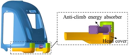
Figure 1.
Assembly relationship description.
2.2. Analysis of Mechanical Characteristics of CAEA
This study conducted dynamic impact tests on CAEA to determine its force–displacement curve. The experimental setup is shown in Figure 2. The CAEA was installed at the front end of a trolley with a mass of 27 t, with only anti-climbing teeth installed on the rigid wall. To ensure the two anti-climbing teeth engage with each other during a collision, a 40 mm eccentric height difference was selected between the two anti-climbing teeth. The trolley was supplied with a certain speed via the power launch system, causing the CAEA at the front end of the trolley to collide with the anti-climbing teeth on the rigid wall. High-speed camera 1 was located above the center point of the collision, high-speed camera 2 was located to the side of the center point of the collision, and the speed sensor was located 2.9 m from the rigid wall, at the position where the CAEA was about to collide with the rigid wall.
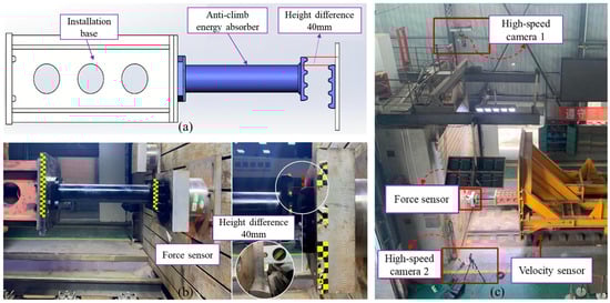
Figure 2.
Experimental setup: (a) workout layout diagram; (b) on-site installation diagram; (c) test equipment layout diagram.
Figure 3 reveals the force–displacement curve of the CAEA and the deformation before and after the collision. The length of the specimen before the collision was 620 mm, the length of the specimen on the rear car after the collision was 40 mm, and the total deformation was 580 mm. Throughout the collision, there is first an IPCF, which is due to the plastic yielding of the specimen. After this peak, the curve enters a period of stable plateau. A sharp increase in force occurs when the displacement exceeds 543.7 mm, at which stage the collapsed specimen is fully compacted. The energy absorbed through plastic deformation in this collision test is 448 kJ.
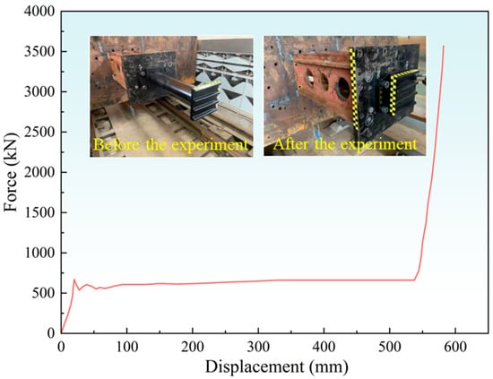
Figure 3.
Force–displacement curve of CAEA.
2.3. Collision Test of the CAEA with GFRP Head Cover
2.3.1. Test Condition Setting
The collision scene test layout is shown in Figure 4. The instruments and equipment used in the collision test of the CAEA with GFRP head cover mainly include a test trolley, power launch system, rigid wall, force sensor, high-speed camera, and speedometer. When designing and installing AEAs for subway vehicles, the vertical dynamic displacement of the train is usually taken into account. According to the European standard EN15227 [32], a pair of AEAs were installed with an offset arrangement. The specimen at one end of the rigid wall was 40 mm vertically lower than the specimen at one end of the trolley, so that the two anti-climb teeth at the ends of the AEAs were just engaged. The overall test arrangement is shown in Figure 4a. In the experiment, a 27-t test trolley was accelerated by a power launch system and then crashed into a rigid wall. The speedometer is placed in the middle of the track, 5.4 m away from the rigid wall, which can measure the speed when the head cover at the moving end contacts the head cover at the stationary end. Figure 4b is a detailed assembly diagram of the GFRP head cover, CAEA, and installation base. The installation base is designed as a hollow steel structure, which is connected to the CAEA through four bolts. The GFRP head cover specimen used in the experiment is 4 mm thick and is divided into upper and lower parts. The rear half of the head cover is connected to the installation base by five bolts to determine the assembly relationship between the CAEA and the GFRP head cover. The arrangement of the rigid wall and force sensor is shown in Figure 4c. This experiment employed a force sensor of model FC-500t, supplied by the AVIC Changchun Institute of Metrology and Measurement (Changchun, China). The model of the high-speed camera is MEMRECAM HX-6E, provided by NAC (Tokyo, Japan).
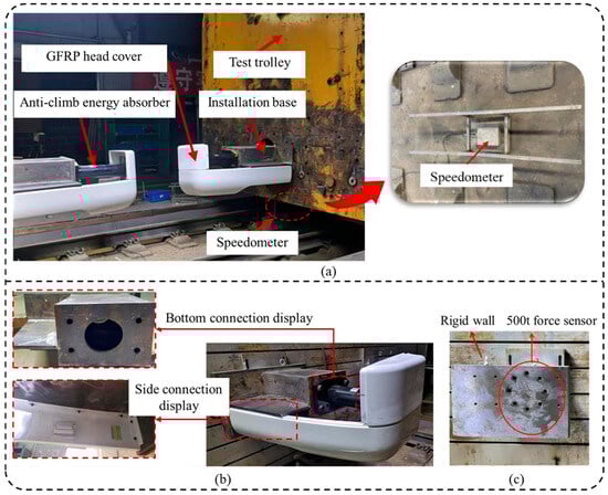
Figure 4.
Collision test scene diagram: (a) overall layout of test equipment; (b) force sensor layout; (c) force sensor layout.
2.3.2. Analysis of Collision Experiment Results
The collision deformation sequence diagram of the test specimen is shown in Figure 5a. According to the collision deformation sequence diagram, the entire collision process proceeds in an orderly manner, and the two CAEAs are successfully engaged. At the end of the collision of the CAEA, the upper and lower parts of the fiberglass head cover at one end of the rigid wall separated. The connection between the CAEA and the installation base at the rigid wall end was bent and deformed, and the fibers at this damaged area were still connected. In addition, the GFRP head cover had local tears at the anti-climbing tooth meshing point. Figure 5b depicts the force–displacement curve of the anti-climbing energy absorber with a GFRP head cover during the crash test. A sharp IPCF appears at the initial position of the curve, which corresponds to the beginning of the energy absorber collapse. Afterwards, the force value decreased and stabilized in a relatively flat area. Due to the bending and twisting of the head cover at the end of the collision, the force–displacement curve shows a brief mutation at the end stage. The energy–displacement curve is shown in Figure 5c. During the entire crushing process, the energy increases monotonically, and the total energy absorbed is 184.99 kJ.
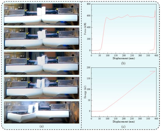
Figure 5.
Collision test results: (a) deformation sequence diagram; (b) force–displacement curve; (c) energy–displacement curve.
3. Finite Element (FE) Modeling and Validation of CAEA with GFRP Head Cover
3.1. Detailed Information on the FE Modeling of CAEA with GFRP Head Cover
The FE model of the CAEA with GFRP head cover is shown in Figure 6. The GFRP head cover is made based on the resin transfer molding process. The head cover is divided into upper and lower parts, both with a thickness of 4 mm. It consists of a total of 12 uniformly thick GFRP plies, and the ply sequence follows an alternating pattern of [−45°/45°]. To accurately simulate the morphologies that are clearly observed in tests such as penetration and delamination of laminates, shell elements are used for delamination modeling. Due to the anti-climbing teeth being relatively thick and having high stiffness, solid elements are used for simulation. In addition, since the vehicle body model is relatively large and this study focuses on exploring the influence of the mechanical properties of the CAEA on the damage characteristics of the GFRP head cover, the installation base is used to replace the vehicle body during simulation modeling. The density of the installation base is increased to make its mass the same as that of a real subway vehicle. The energy-absorbing part of the CAEA is simplified and modeled using the beam element model, and the force–displacement curve obtained in Section 2.2 is input to simulate the energy absorption process. The CAEA is eccentrically installed with a height difference of 40 mm. The CAEA with a GFRP head cover at the moving end is entirely higher than that with a GFRP head cover at the stationary end.
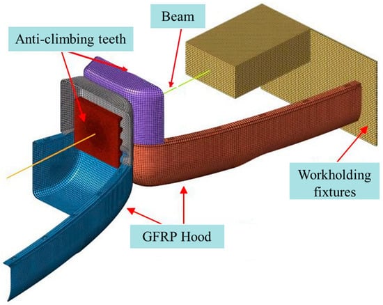
Figure 6.
FE model of CAEA with GFRP head cover.
Considering that the installation base and anti-climbing teeth have almost no contribution to energy absorption and taking into account computational efficiency, the mesh size of both the installation base and anti-climbing teeth is selected to be 10 mm. A mesh convergence analysis was performed on the GFRP head cover to determine the appropriate mesh size for the head cover, as shown in Figure 7. To balance accuracy and computational efficiency, the mesh size of the shell elements for the GFRP head cover was set as 8 mm. After meshing, there were a total of 71,513 solid elements and 51,329 nodes. To simplify the model, CONSTRAINED_EXTRA_NODES are used to connect the beam elements with the CAEAs and the installation base. The connection between the upper and lower parts of the GFRP head cover uses the TIED_AUTOMATIC_SURFACE_TO_SURFACE_FAILURE contact algorithm to simulate the bolt connection and bolt failure. The bolt connection between the installation base and the GFRP head cover is simulated using the TIED_NODE_TO_SURFACE contact algorithm. In addition, the AUTOMATIC_SINGLE_SURFACE contact algorithm and AUTOMATIC_SURFACE_TO_SURFACE contact algorithm adopted in this model are applied to the self-contact of the overall structure and the contact between the AEA and the GFRP head cover, respectively. Both the static and dynamic friction coefficients are defined as 0.2 [33].
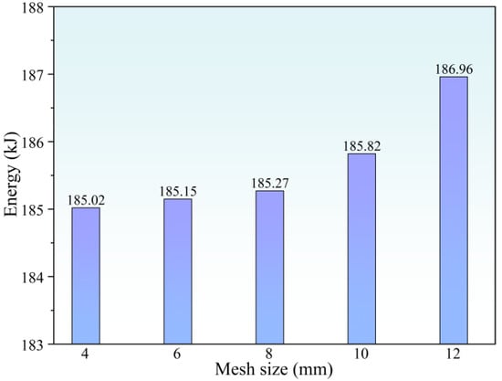
Figure 7.
The convergence analysis with different mesh sizes for GFRP head cover.
The GFRP head cover was simulated using the MAT_54 material model in 2021 version LS_DYNA. This material model determines the interlaminar failure behavior based on the Chang–Chang failure criterion. In this study, the parameters of the MAT_54 material model were set according to the mechanical properties in the previous research by the author team [34] and are summarized in Table 1.

Table 1.
Material properties parameters of GFRP [33].
3.2. Model Validation of CAEA with GFRP Head Cover
Figure 8 is a comparison diagram of the experimental and simulated collision process sequences. According to the deformation of the GFRP head cover at different collision moments, it can be found that its upper and lower parts are separated in both simulation and experiment, and wrinkles and tears are generated at its front end. At the end of the collision, the GFRP head cover at the stationary end of the experiment suffered a torsional fracture at the connection with the installation base, while only torsion occurred without fracture in the simulation. Considering that the meshing of the CAEA is affected by the collision center position, this difference can be ignored.
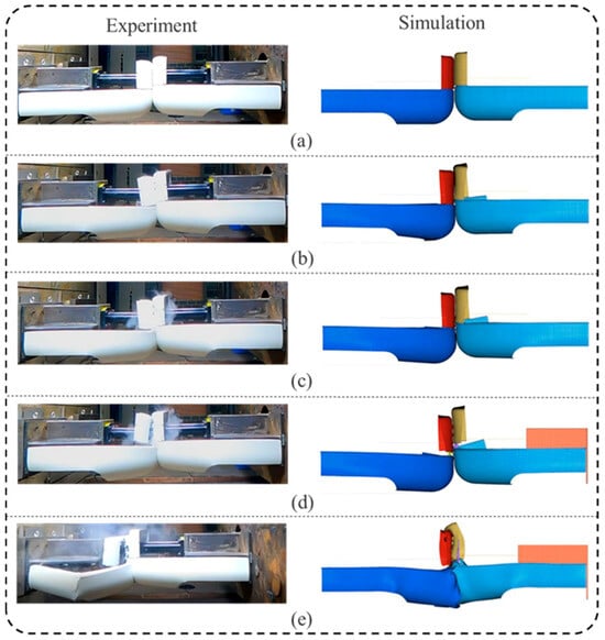
Figure 8.
Comparison of experimental and simulation collision deformation results: (a) contact moment of the head cover; (b) contact moment of the CAEA; (c) middle moment of the collision; (d) separation moment of the upper and lower parts of the head cover; (e) end moment of the collision.
Figure 9a is a comparison of the force–displacement curves of the experiment and simulation. Figure 9b shows the comparison diagram of the energy–displacement curves between the experiment and the simulation. The energies absorbed in the collision test and the FE simulation are 184.99 kJ and 185.27 kJ, respectively, and the relative error between the two is only 0.54%. Apparently, the simulation model exhibits relatively high accuracy and can be employed for subsequent parameter analysis research.
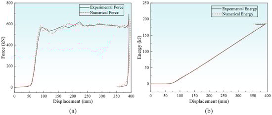
Figure 9.
Comparison of experimental and simulation results for the CAEA with GFRP head cover: (a) comparison of force–displacement curves; (b) comparison of energy–displacement curves.
4. Influence of CAEA Mechanical Characteristic Parameters on the Collision Behavior of the Head Cover
4.1. Definition of Mechanical Characteristic Parameters
The IPCF, platform force, and compaction force generated during CAEA collision have a significant impact on the damage performance of the GFRP head cover. However, the damage performance of the GFRP head cover will greatly affect the meshing between the anti-climbing teeth, thereby affecting the energy absorption process of the AEA. Therefore, it is necessary to study the influence of the mechanical characteristic parameters of the CAEA on the collision behavior of the GFRP head cover.
Based on the CAEA in Section 2.2, three mechanical characteristic parameters, namely the IPCF, the platform force, and the compaction force, are extracted from its force–displacement curve for research. The IPCF ranges from 500 kN to 1000 kN, the platform force ranges from 400 kN to 700 kN, and the compaction force ranges from 2000 kN to 4000 kN, as shown in Figure 10. Moreover, simulation models with different mechanical properties were constructed to investigate the influence of three mechanical characteristic parameters on the collision behavior of the GFRP head cover.
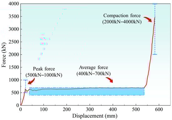
Figure 10.
The range of values for three mechanical characteristics.
This study marked points A and B in the FE model of the GFRP head cover to record the displacement and velocity during the collision process, as shown in Figure 11. Through this method, it is possible to explore the displacement–time curve of the AEA at the moving end, the velocity–time curve at point A, the force–time curve of the interface force, and the trend of the energy after the collision of the specimen under different mechanical characteristic parameters.
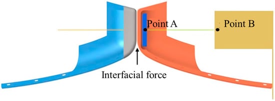
Figure 11.
Schematic diagram of FE model output identification points.
4.2. Influence of IPCF on the Collision Behavior of GFRP Head Cover
IPCF may affect the time when the GFRP head cover begins to break. To investigate the mechanical behavior changes in the GFRP head cover under different peak forces of AEA, the IPCF values in the force displacement curve were systematically adjusted to 500 kN, 625 kN, 750 kN, 875 kN, and 1000 kN, as shown in Figure 12.
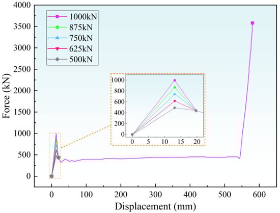
Figure 12.
Force–displacement curves for five different IPCFs.
Figure 13 depicts the mechanical responses obtained under different IPCF conditions. Figure 13a shows the velocity–time curve, and it can be seen that as the IPCF increases, the first valley of the vehicle’s velocity decreases, indicating that the deceleration experienced by the vehicle during a collision is greater. The displacement–time curve shown in Figure 13b shows that the displacement of the working conditions with IPCF of 1000 kN and 875 kN after 25 ms is significantly different from the other three working conditions. The final displacement is 32 mm and 24 mm, respectively, which is 17.9% and 38.5% less than the 39 mm of the other three working conditions. The curve in Figure 13c represents the force–time curve, and it can be observed that the change in the IPCF has a relatively small impact on the initial interface force of the GFRP head cover. However, the impact becomes greater when the anti-climbing teeth are engaged. Figure 13d displays the energy bar chart, and it is evident that as the IPCF increases, the energy absorption of the GFRP head cover also gradually increases. The maximum energy absorption when IPCF is 1000 kN is 554.02 kJ.
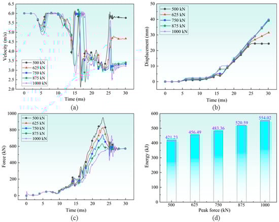
Figure 13.
Five sets of collision responses with different IPCFs: (a) velocity–time diagram; (b) displacement–time diagram; (c) force–time diagram; (d) energy absorption diagram.
Figure 14 shows the deformation and stress cloud diagrams of the GFRP head cover under different IPCFs. It can be found that after the collision, the lower half of the moving end of the five groups of GFRP head covers all underwent a certain degree of torsional deformation, and the upper half was pressed out with tooth marks by the anti-climbing teeth, but no significant damage or deformation occurred. As the IPCF increased, damaged pores gradually appeared in the GFRP head cover at the moving end, and the stress gradually increased. The stress of the GFRP head cover at the stationary end gradually decreased with the increase in IPCF, but the difference was not significant.
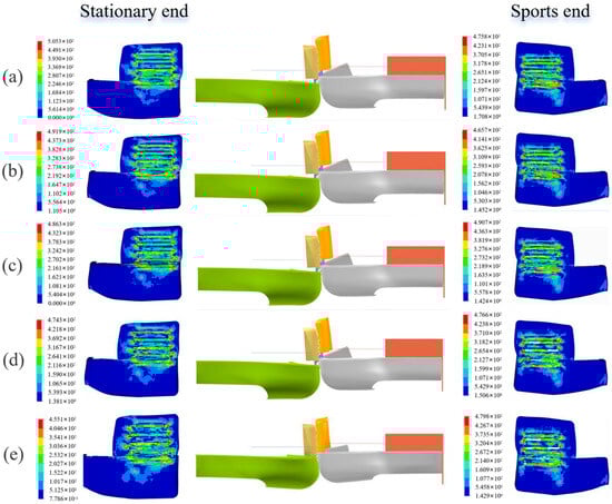
Figure 14.
Deformation and stress cloud map after collision with different IPCFs: (a) 500 kN; (b) 625 kN; (c) 750 kN; (d) 875 kN; (e) 1000 kN.
4.3. Influence of Platform Force on the Collision Behavior of GFRP Head Cover
This section investigates the mechanical behavior changes in the GFRP head cover under different AEA platform forces. The platform forces in the force–displacement curve, within the displacement range of 19.7 mm to 543.7 mm, were set to 400 kN, 475 kN, 550 kN, 625 kN, and 700 kN, respectively, as depicted in Figure 15.
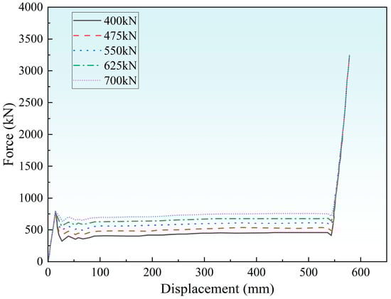
Figure 15.
Force–displacement curves for five different platform forces.
The mechanical curves obtained under different platform forces are shown in Figure 16. From Figure 16a, it can be observed that the effect of the platform force on velocity is concentrated after 25 ms, and as the platform force increases, the velocity gradually decreases. From Figure 16b, it can be seen that as the platform force increases, the displacement shows a gradually increasing trend, but the increase gradually decreases. From the curve in Figure 16c, it can be seen that for different platform force values, the GFRP head cover exhibits a stable contact force, and as the platform force increases, its stable force value shows a linear increasing trend. It can be clearly seen from the curve in Figure 16d that as the platform force increases, the energy absorption after collision becomes higher and the energy absorption effect becomes better.
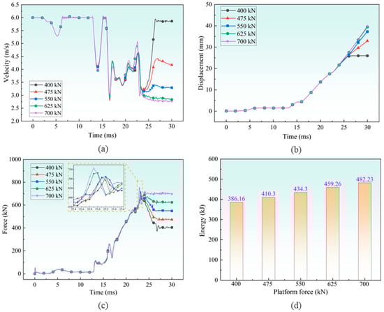
Figure 16.
Five sets of collision responses with different platform forces: (a) velocity–time diagram; (b) displacement–time diagram; (c) force–time diagram; (d) energy absorption diagram.
Figure 17 presents the deformation and stress cloud maps of GFRP headgear under different platform forces. It can be clearly seen from the figure that due to the concentration of energy at the connection between the upper and lower parts of the head cover, the upper and lower parts of each group of head covers have failed and separated during the collision process, and the lower half of the head cover at the moving end has undergone greater bending and twisting deformation compared to the lower half of the head cover at the stationary end. In addition, combining Figure 16c and Figure 17, it can be observed that the location of peak force will move forward with the increase in platform force value. This is because the larger the platform force, the earlier the GFRP head cover ruptures, and the AEA comes into contact earlier, resulting in an increase in contact force.
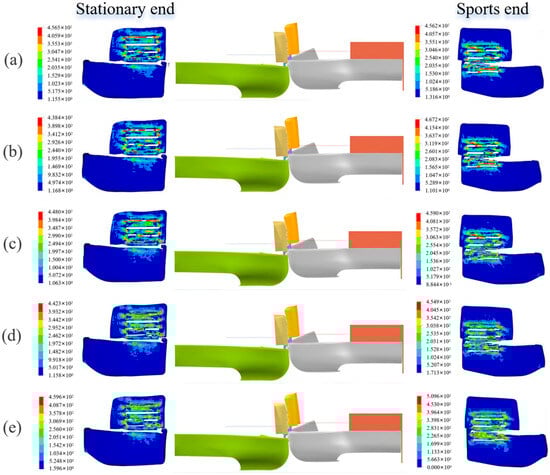
Figure 17.
Deformation and stress cloud map after collision with different platform forces: (a) 400 kN; (b) 475 kN; (c) 550 kN; (d) 625 kN; (e) 700 kN.
4.4. Influence of Compaction Force on the Collision Behavior of GFRP Head Cover
The present study investigated the collision responses of the GFRP head cover under varying compaction forces of the CAEA. Five FE models were developed, each with a distinct CAEA compaction force, ranging from 2000 kN to 4000 kN in 500 kN increments, as depicted in Figure 18.
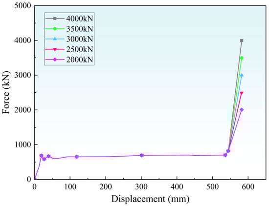
Figure 18.
Force–displacement curves for five different compaction forces.
Figure 19 represents the mechanical curves obtained under different compaction forces. It can be clearly seen from the figure that the energy absorption of the GFRP head cover is relatively close at compaction forces of 2000 kN and 2500 kN, and the energy absorption at compaction forces of 3000 kN, 3500 kN, and 4000 kN are also relatively close, and they are all higher than the working conditions at compaction forces of 2000 kN and 2500 kN. Similarly to energy absorption, the velocity–time, displacement–time, and force–time curves also exhibit similar situations. This indicates that there is a critical value of compaction force between 2500 kN and 3000 kN, which enables various mechanical properties to transition from one trend to another. This critical value seems to mark the transition of the hood’s impact behavior. It is worth noting that the evolution trends of velocity, displacement, and force remain consistent under different compaction forces, indicating that the compaction force has no significant effect on the deformation of the GFRP hood before compression.
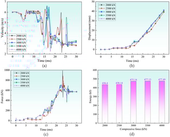
Figure 19.
Five sets of collision responses with different compaction forces: (a) velocity–time diagram; (b) displacement–time diagram; (c) force–time diagram; (d) energy absorption diagram.
From Figure 20, it can be seen that the damage performance of the GFRP head cover after the collision is similar to the trend of energy absorption. The working conditions with compaction forces of 2000 kN and 2500 kN produced larger damage pores on the GFRP head cover, while the damage pores of the other three groups were similar.
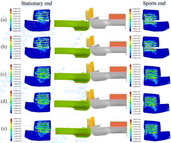
Figure 20.
Deformation and stress cloud map after collision with different compaction forces: (a) 2000 kN; (b) 2500 kN; (c) 3000 kN; (d) 3500 kN; (e) 4000 kN.
4.5. Influence of Eccentric Height Difference on Collision Behavior of GFRP Head Cover
The installation position of the CAEA on the train also takes into account the vertical dynamic displacement between the anti-creep teeth of the two colliding trains, that is, eccentric collision. The eccentric height difference which caused by the eccentric collision will directly influence the contact area of two sides anti-climbing teeth, and then influence the force distributed to the GFRP head cover. It is thus required to consider the eccentric height difference in the CAEA as one of the investigation factors. In the following basic contents, five simulated models with various eccentric height difference between AEA were established and the deployment of each displacement was such that anti-climbing teeth on both sides could just mesh, as shown in Figure 21. The eccentric height differences in the anti-climbing teeth are set to 40 mm, 120 mm, 200 mm, and 280 mm, respectively.
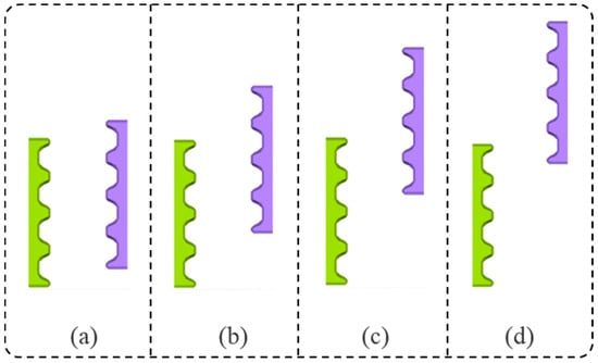
Figure 21.
Schematic diagrams of different eccentric height differences: (a) 40 mm; (b) 120 mm; (c) 200 mm; (d) 280 mm.
Figure 22 indicates the mechanical curves obtained under different eccentric height differences. From the figure, it can be seen that due to the influence of eccentric height difference on the contact area, the deceleration generated in the initial stage of collision decreases with the increase in eccentric height difference. At the end of the collision, the minimum velocity is the 280 mm eccentric height difference. This is because the collision energy under the 280 mm eccentric height difference condition is dissipated in the bending of the GFRP head cover, resulting in the minimum velocity after stabilization. The displacement remains basically consistent under several different eccentric height difference conditions. The force increases first and then decreases with the increase in eccentric height difference, and finally stabilizes at around 550 kN. As the eccentric height difference increases, the energy absorbed by the GFRP head cover shows a decreasing trend. The energy absorption of the working condition with an eccentric height difference of 280 mm is the smallest, at 385.64 kJ, because the bending deformation of the GFRP head cover weakens the cutting energy absorption.
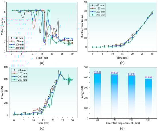
Figure 22.
Four sets of collision responses with different eccentric height differences: (a) velocity-time curve; (b) displacement-time curve; (c) force-time curve; (d) energy absorption diagram.
Based on the damage situation of different eccentric height differences presented in Figure 23 and Figure 24, it can be seen that for the working conditions with eccentric height differences of 40 mm and 120 mm, the deformation mode is similar, and the GFRP head cover does not undergo significant torsion, mainly absorbing energy through tearing of the GFRP head cover. In addition, the crushing modes of the working conditions with eccentric height differences of 40 mm and 120 mm are similar, with only positional deviation occurring. The working condition with an eccentric height difference of 200 mm showed a significant twisting phenomenon of GFRP head cover, and the damage mode became less obvious. For the working condition with an eccentric height difference of 280 mm, the head cover wrapped around the front end of the AEA almost did not deform. The deformation was mainly achieved by twisting the lower part of the anti-climbing energy absorber, and the damage to the stationary and moving ends was significantly reduced. In addition, separation phenomena were observed in the upper and lower parts of the GFRP head cover for all four operating conditions.
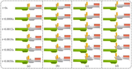
Figure 23.
Collision sequence diagram with different eccentric height differences: (a) 40 mm; (b)120 mm (c) 200 mm; (d) 280 mm.
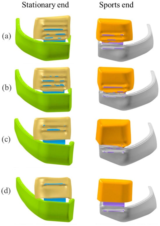
Figure 24.
Deformation of the GFRP head cover after collision: (a) 40 mm; (b)120 mm; (c) 200 mm; (d) 280 mm.
5. Conclusions
This paper first obtained various mechanical curves of CAEA through impact testing. Secondly, a collision simulation model of GFRP head cover was established. Then, the reliability of the established FE collision simulation model was verified through experiments. Finally, using the validated model, 5 different IPCFs, 5 different platform forces, 5 different compaction forces, and 4 different eccentric height differences were designed based on the mechanical curve and installation characteristics of AEA to study their effects on the collision behavior of GFRP head cover. The specific conclusion is as follows:
(1) With the increase in IPCF, the energy absorption of GFRP head cover gradually increases and shows a linear increasing trend. And as the peak force increases, damaged pores appear in the GFRP head cover at the moving end, and the stress at the moving end gradually increases.
(2) The higher the platform force, the earlier the GFRP head cover ruptures, and the energy absorbing and anti-climbing structure comes into contact earlier, resulting in an increase in contact force. In addition, the higher the platform force, the smaller the difference between the peak contact force and the stabilizing force, the smaller the acceleration, and the smoother the energy absorption process. As the platform force increases, the higher the energy absorption after collision, the better the energy absorption effect.
(3) The collision behavior of the GFRP head cover showed little change at compaction forces of 2000 kN and 2500 kN. Compaction forces between 3000 and 4000 kN also showed little change. However, there was a critical value between 2500 kN and 3000 kN, at which the collision behavior of the GFRP head cover (collision velocity, displacement, force, and deformation mode) underwent a radical change.
(4) As the eccentric height difference in the anti-climbing teeth increases from 40 mm to 280 mm, the damage form of the GFRP head cover gradually changes from tearing deformation to torsional deformation. The collision energy absorption decreases from 440.41 kJ to 385.64 kJ, a decrease of 12.44%.
Author Contributions
Conceptualization, X.L. and Y.G.; methodology, Y.H.; software, Y.G.; validation, D.W., Y.G. and P.X.; formal analysis, D.W.; investigation, Y.H.; re-sources, P.X.; data curation, Y.G.; writing—original draft preparation, X.L.; writing—review and editing, P.X.; visu-alization, Y.H.; supervision, D.W.; project administration, X.L.; funding acquisition, D.W. All authors have read and agreed to the published version of the manuscript.
Funding
The research was funded by the Hunan Provincial Department of Education Scientific Research Outstanding Youth Project (No. 24B1026) and Hunan Provincial Natural Science Foundation (No. 2023JJ60216). The financial supports are gratefully acknowledged.
Data Availability Statement
No new data were created or analyzed in this study. Data sharing is not applicable to this article.
Acknowledgments
The authors are grateful to Shuguang Yao at CSU for insightful discussion.
Conflicts of Interest
The authors declare no conflicts of interest. Author Dongtao Wang was employed by the company CRRC Zhuzhou Institute Co., Ltd.
References
- Gao, G.; Guan, W.; Li, J.; Dong, H.; Zou, X.; Chen, W. Experimental investigation of an active–passive integration energy absorber for railway vehicles. Thin-Walled Struct. 2017, 117, 89–97. [Google Scholar] [CrossRef]
- Dąbrowski, F.; Grzejszczyk, Z.; Rzymkowski, C.; Wiśniewski, P. Frontal Impact Energy Absorbers for Passenger Cars. Sensors 2024, 24, 6563. [Google Scholar] [CrossRef]
- Wei, W.; Zhang, F.; Xing, Y.; Wang, H.; Liu, R. Research on Mechanical Properties of Origami Aluminum Honeycomb for Automobile Energy Absorbing Box. Materials 2022, 16, 141. [Google Scholar] [CrossRef]
- Guan, W.; Gao, G. Crashworthiness analysis of shrink circular tube energy absorbers with anti-climbers under multiple loading cases. Mech. Adv. Mater. Struct. 2022, 30, 1453–1469. [Google Scholar] [CrossRef]
- Li, Y.; Zhang, H.; Xie, J.; Xiao, S.; Zhu, T.; Zhou, G.; Xu, L. Energy Absorption Characteristics and Parameter Optimization of Anti-Climb Energy-Absorbing Devices for Subway Vehicles under Impact Loads. Appl. Sci. 2024, 14, 5203. [Google Scholar] [CrossRef]
- Jeon, K.-W.; Shin, K.-B.; Kim, J.-S. A study on evaluation of fatigue strength of a GFRP composite bogie frame for urban subway vehicles. Adv. Compos. Mater. 2013, 22, 213–225. [Google Scholar] [CrossRef]
- Chaudhari, A.B.; Gohil, P.P.; Chaudhary, V. Experimental investigations on high speed drilling of unidirectional GFRP composites. Int. J. Interact. Des. Manuf. 2024, 19, 4177–4191. [Google Scholar] [CrossRef]
- Sommer, D.E.; Berkowitz, K.; Werner, B.T.; Long, K.N.; Skulborstad, A.J. Numerical modeling and experimental validation of low velocity impact of woven GFRP/CFRP composites. J. Compos. Mater. 2024, 59, 283–303. [Google Scholar] [CrossRef]
- Milho, J.F.; Ambrósio, J.A.C.; Pereira, M.F.O.S. A multibody methodology for the design of anti-climber devices for train crashworthiness simulation. Int. J. Crashworthiness 2002, 7, 7–20. [Google Scholar] [CrossRef]
- Li, B.; Lu, Z.; Yan, K.; Lu, S.; Kong, L.; Xu, P. Experimental study of a honeycomb energy-absorbing device for high-speed trains. Proc. Inst. Mech. Eng. Part F J. Rail Rapid Transit 2019, 234, 1170–1183. [Google Scholar] [CrossRef]
- Demirci, E.; Yıldız, A.R. An investigation of the crash performance of magnesium, aluminum and advanced high strength steels and different cross-sections for vehicle thin-walled energy absorbers. Mater. Test. 2018, 60, 661–668. [Google Scholar] [CrossRef]
- Li, Z.; Yang, H.; Hu, X.; Wei, J.; Han, Z. Experimental study on the crush behavior and energy-absorption ability of circular magnesium thin-walled tubes and the comparison with aluminum tubes. Eng. Struct. 2018, 164, 1–13. [Google Scholar] [CrossRef]
- Wang, Y.; Wang, S.; Hou, L.; Peng, Y. Analysis and Optimization of an Expanding Energy Absorber with Variable Thickness Distribution Tube under Axial Dynamic Loading. Int. J. Automot. Technol. 2022, 23, 1579–1592. [Google Scholar] [CrossRef]
- Zhan, X.; Yu, Y.; Feng, T. Study on energy absorption characteristics of expansion tube with light magnesium alloy. Mech. Based Des. Struct. Mach. 2022, 52, 425–446. [Google Scholar] [CrossRef]
- Gao, G.; Wang, S. Crashworthiness of passenger rail vehicles: A review. Int. J. Crashworthiness 2019, 24, 664–676. [Google Scholar] [CrossRef]
- Gao, G.; Zhuo, T.; Guan, W. Recent research development of energy-absorption structure and application for railway vehicles. J. Cent. South Univ. 2020, 27, 1012–1038. [Google Scholar] [CrossRef]
- Guo, W.; Yang, C.; Xu, P.; Yang, L.; Wen, Y.; Jin, X. Crashworthiness optimization for cutting energy-absorbing structures based on the multiobjective G-CBW method. Alex. Eng. J. 2023, 72, 363–383. [Google Scholar] [CrossRef]
- Hu, Z.; Guo, L.; Zhang, Y. Design and Numerical Simulation of a Ball Cutting Type Energy Absorber Device. J. Phys. Conf. Ser. 2021, 1802, 042076. [Google Scholar] [CrossRef]
- Luo, H.; Qi, Z.; Zhang, Y.; Liang, M.; Lin, Y. Design of device for testing the energy of explosion shock waves based on a lever-type cutting energy-absorbing structure. Meas. Sci. Technol. 2023, 35, 035103. [Google Scholar] [CrossRef]
- Peng, Y.; Zhou, J.; Hou, L.; Wang, K.; Chen, C.; Zhang, H. A hybrid MCDM-based optimization method for cutting-type energy-absorbing structures of subway vehicles. Struct. Multidiscip. Optim. 2022, 65, 228. [Google Scholar] [CrossRef]
- Shuhao, L.; Qian, Z.; Xudong, Z.; Rongqiang, L.; Rong, Z. Experimental and numerical study on the low-velocity impact behavior of metal-cutting energy absorbers. Alex. Eng. J. 2025, 122, 130–151. [Google Scholar] [CrossRef]
- Guan, W.; Gao, G.; Li, J.; Yu, Y. Crushing analysis and multi-objective optimization of a cutting aluminium tube absorber for railway vehicles under quasi-static loading. Thin-Walled Struct. 2018, 123, 395–408. [Google Scholar] [CrossRef]
- Wang, J.; Lu, Z.; Zhong, M.; Wang, T.; Sun, C.; Li, H. Coupled thermal–structural analysis and multi-objective optimization of a cutting-type energy-absorbing structure for subway vehicles. Thin-Walled Struct. 2019, 141, 360–373. [Google Scholar] [CrossRef]
- Peng, Y.; Wang, S.; Yao, S.; Xu, P. Crashworthiness analysis and optimization of a cutting-style energy absorbing structure for subway vehicles. Thin-Walled Struct. 2017, 120, 225–235. [Google Scholar] [CrossRef]
- Luo, H.; Yan, Y.; Zhang, T. Gradually failure simulation and energy absorption characteristics of GFRP composite tubes subjected to axial dynamic impact. Polym. Compos. 2018, 40, 1545–1555. [Google Scholar] [CrossRef]
- Zniker, H.; Ouaki, B.; Bouzakraoui, S.; EbnTouhami, M.; Mezouara, H. Energy absorption and damage characterization of GFRP laminated and PVC-foam sandwich composites under repeated impacts with reduced energies and quasi-static indentation. Case Stud. Constr. Mater. 2022, 16, e00844. [Google Scholar] [CrossRef]
- Mack, J.P.; Mirza, F.; Banik, A.; Khan, M.H.; Tan, K.T. Hybridization of face sheet in sandwich composites to mitigate low temperature and low velocity impact damage. Compos. Struct. 2024, 338, 118101. [Google Scholar] [CrossRef]
- Gupta, A.K.; Velmurugan, R.; Joshi, M.; Gupta, N.K. Studies on shape memory alloy-embedded GFRP composites for improved post-impact damage strength. Int. J. Crashworthiness 2018, 24, 363–379. [Google Scholar] [CrossRef]
- Su, S. Numerical Study on the Impact Resistance of a Composite Engine Head cover. Mech. Compos. Mater. 2023, 59, 869–884. [Google Scholar] [CrossRef]
- Kim, D.-H.; Jung, K.-H.; Kim, D.-J.; Park, S.-H.; Kim, D.-H.; Lim, J.; Nam, B.-G.; Kim, H.-S. Improving pedestrian safety via the optimization of composite head cover structures for automobiles based on the equivalent static load method. Compos. Struct. 2017, 176, 780–789. [Google Scholar] [CrossRef]
- Zhang, J.; Wang, X.; Geng, Y.; Chea, C.P.; Gao, D.; Wang, N.; Guan, C.; Wang, J.; Yue, F. The analysis of crashworthiness and energy dissipation mechanism of novel rotational guiding anti-collision device using fiber reinforced composites. Ocean Eng. 2025, 317, 120030. [Google Scholar] [CrossRef]
- EN 15227: 2020; Railway Applications—Crashworthiness Requirements for Railway Vehicle. iTeh, Inc.: Newark, DE, USA, 2011.
- Lin, Y.L.; Qin, J.G.; Chen, R.; Zhao, P.D.; Lu, F.Y. A technique for measuring dynamic friction coefficient under impact loading. Rev. Sci. Instrum. 2014, 85, 094501. [Google Scholar] [CrossRef] [PubMed]
- Yang, C.; Gao, Y.; Guo, W.; Yang, Y.; Xu, P.; Alqahtani, M.S. High-velocity impact behaviour of curved GFRP composites for rail vehicles: Experimental and numerical study. Polym. Test. 2022, 116, 107774. [Google Scholar] [CrossRef]


Disclaimer/Publisher’s Note: The statements, opinions and data contained in all publications are solely those of the individual author(s) and contributor(s) and not of MDPI and/or the editor(s). MDPI and/or the editor(s) disclaim responsibility for any injury to people or property resulting from any ideas, methods, instructions or products referred to in the content. |
© 2025 by the authors. Licensee MDPI, Basel, Switzerland. This article is an open access article distributed under the terms and conditions of the Creative Commons Attribution (CC BY) license (https://creativecommons.org/licenses/by/4.0/).