Abstract
There is limited research on robotic systems designed for Endoscopic Retrograde Cholangiopancreatography (ERCP) procedures using a side-view duodenoscope. The unique structure of the duodenoscope presents challenges to safely and precisely control the distal end pose. Control methods applied can reduce potential medical risks. We have redesigned the control section of the duodenoscope to facilitate its manipulation by a robotic system. An orthogonal compensator is employed to rectify the motion planes to standard planes. A hysteresis compensator based on the Prandtl-Ishlinskii model enables precise control of the distal pose of the duodenoscope. Furthermore, we utilize a contact force prediction model to prevent excessive contact force at the distal end. The performance of the modified duodenoscope is comparable to that of the standard duodenoscope. Following orthogonal compensation, the deviation angles of the motion planes is reduced by 32% to 98%. Post-hysteresis compensation, the root mean square error (RMSE) of the output angle of the distal end is decreased from 8.347° to 4.826°. The accuracy of distal end contact force prediction was approximately ±25% under conditions of high contact force. In conclusion, the modification and control strategy we proposed can achieve relatively safe and precise control of bending section, laying the foundation for the subsequent roboticization of duodenoscope systems for ERCP procedures.
1. Introduction
Endoscopic retrograde cholangiopancreatography (ERCP) has been widely used for the treatment of obstructive jaundice, as well as diseases of the biliary or pancreatic duct systems. However, current ERCP procedures still pose challenges in terms of ergonomic burden. Studies have indicated that physicians experience varying degrees of musculoskeletal injuries [1]. The introduction of robotic technology holds promise in alleviating the physical strain on physicians.
Most ERCP procedures utilize side-viewing duodenoscopes as shown in Figure 1. There is limited research on duodenoscope surgical robotics [2], with most studies focusing on gastroscopes or colonoscopes. There are two main approaches to achieve endoscope robotization. One approach involves compatibility with standard endoscopes [3,4,5,6,7]. These systems mount gears or similar transmission structures onto the knobs of standard endoscopes, allowing manipulation of the endoscope’s distal end. This approach usually requires multiple steps to confirm the gears and clamping device are properly installed [3,4]. Another approach to achieve robotization involves modifying existing endoscopes, such as the NeoGuide [5], K-Flex [6], and i2Snake [7] platforms. However, these platforms sacrifice volume to meet various surgical types, resulting in endoscope diameters exceeding 16 mm, whereas standard endoscopes have diameters less than 12 mm, which cause more discomfort to the patient.
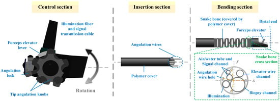
Figure 1.
Duodenoscope schematic. The snake bone in the bending section contains multiple cables and channels running internally. The angulation wire holes are not evenly distributed at the four corners.
The commonly adopted driving mechanism for an endoscope is the Tendon-Sheath-Mechanism (TSM) [8]. However, the TSM structure has certain limitations. During motion, the dead zone effect appears due to one side of the tendon being slack during direction change. Additionally, there is a backlash effect due to frictional forces reversing during direction change, which limits the precision of the controlled end effector position, as depicted in Figure 2. In surgical robot control, precise knowledge of the robot’s distal end pose is often required for accurate surgical control and for safety reasons. Therefore, many control methods have been proposed to alleviate the hysteresis of TSM [9,10,11,12,13]. These methods can be classified into online and offline compensation approaches. Online methods typically use sensors or camera images to estimate the end effector pose. However, the sensors used (such as FBG sensors and electromagnetic sensors) often have issues with sterilization, size constraints, and limited lifespan. Camera images are limited by image quality and may not be robust. As for offline compensation methods, they can be primarily divided into three categories: physics-based methods, learning-based methods, and hysteresis mathematical model-based methods. Physics-based models directly model the motion of the snake bone [14,15], but these models often make assumptions that deviate from actual conditions, affecting modeling accuracy. Learning-based methods are data-driven [11,12], requiring large amounts of data, and it’s challenging to assess the stability and robustness of the model. Hysteresis mathematical model-based methods typically include Bouc-Wen models, Duhem models, Preisach models, Prandtl-Ishlinskii models, etc. These models directly model the hysteresis effect. Among these, only the Prandtl-Ishlinskii model can provide an accurate inverse kinematic model [16].
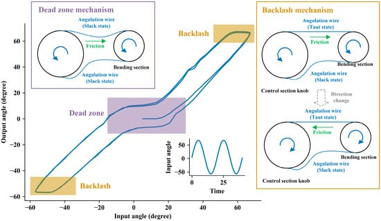
Figure 2.
The structure of TSM and a hysteresis diagram. Dead zones and backlash lead to inconsistencies between input and output.
It is typically assumed that the two degrees of freedom bending of the snake bone are independent. However, this assumption may not be correct for duodenoscopes. Due to the additional components at the distal end compared to other endoscopes, the angulation wire holes on the snake bone are not evenly distributed around the circular ring (as shown in Figure 1). This results in the bending of the snake bone not being entirely orthogonal in the U/D (Up and Down) and L/R (Left and Right) directions; thus, their movements are not mutually independent. But for the commonly used robotic surgery systems, the manipulation platform on the physician side typically uses a standard orthogonal coordinate system as the reference for U/D and L/R directions. Therefore, an additional control method is required to provide orthogonal compensation to ensure consistency between the U/D and L/R movements of the duodenoscope and the manipulation platform. Endoscopes with snake bone structure are often categorized under tendon-actuated discrete-jointed designs [17], and using continuum robotic theory to analyze their kinematic models is highly instructive [18]. Cosserat rod theory, for example, has been utilized in endoscope kinematic modeling. But these studies focus solely on either the insertion section [19] or the bending section [20]. Besides, these methods that are based on quantities measured in the control section (e.g., tendon length, tension) have their precision affected by factors such as the compliance of the duodenoscope and friction [18]. Additionally, differential models in continuum robot theory, which have infinite degrees of freedom, require numerical integration or the linear combination of basis functions for approximate solutions, resulting in high computational overhead [21].
Safety is also a crucial aspect of robotic control. Perforation events caused by excessive movement of the duodenoscope during ERCP procedures pose serious risks to patients’ lives [22,23]. The side-viewing duodenoscope’s distal end is not entirely in the sight of the camera, making it difficult to estimate the degree of contact with tissues. Furthermore, using robotic-driven endoscope movements deprives doctors of tactile feedback regarding the resistance encountered by the endoscope, increasing the risk of tissue perforation during surgery. Most solutions utilizing additional sensors to detect forces directly are not ideal. Therefore, it is necessary to predict and set a threshold for the output torque of the duodenoscope’s bending section to reduce the risk of perforation.
Based on the aspects mentioned above, the duodenoscope design and control methods we propose for ERCP procedures encompass several innovative aspects:
- We have designed a new control section structure for side-viewing duodenoscopes used in ERCP procedures. It’s easy to drive and its response is comparable to standard duodenoscopes.
- We have proposed a type of orthogonal and hysteresis compensation controller based on the Prandtl-Ishlinskii model to compensate for the coupling problem of U/D and L/R direction movements and the nonlinear hysteresis effect of bending.
- We utilize torque sensors of bending drive motors to calibrate the internal resistance of the duodenoscope and achieve contact force prediction for the distal end, thereby setting the contact force threshold of the distal end to prevent excessive force during movement.
2. Materials and Methods
2.1. Structure Design
Drive units of our endoscopic robotic system can be divided into multiple parts based on the various degrees of freedom (See Figure 3a). Among these, the bending drive unit could operate the duodenoscope control section, which controlled the distal end pose. The bending drive unit was connected to the modified duodenoscope via a spline structure (see Figure 3b). During the duodenoscope installation process, the bending drive unit controlled the engagement and disengagement of the splines using a spline clutch structure (see Figure 3a). When the spline structure was disengaged, its rotational degree of freedom was locked (see Figure 3c); thereby, locking the rotational freedom of the sprocket and maintaining the curvature of the bending section. When the splined structure was engaged and subjected to axial force, the rotational degree of freedom was unlocked, allowing the sprocket to rotate with the splined structure to control the distal end movement. This locking function acted like the angulation lock on the standard duodenoscope. In case of an emergency during surgery that would necessitate replacing the bending drive unit—for example, with a manual control knob (see Figure 3d)—the locking function could maintain the curvature of the bending section, restricting its movement to prevent accidents.
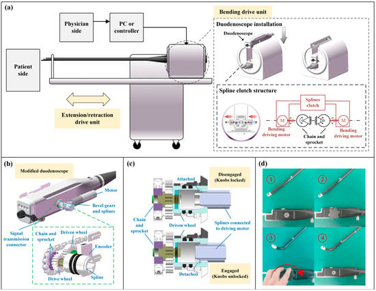
Figure 3.
Structural design schematics. (a) Robotic system schematics. (b) The splines and the sprocket can be driven by the motor’s bevel gear, thereby bending the distal end. (c) When the splines are disengaged, a spring pushes the rotation shaft to attach to a fixed component, locking the rotation shaft; once re-engaged, the rotation shaft will be detached and unlocked. (d) According to the figure sequence from ①–④, the manual control knob can be used to control bending, and the distal end pose remains after the knob is removed.
When driving the sprocket, the drive wheel attached to the splined structure would rotate the driven wheel containing magnetic poles. A magnetic encoder would record the rotation angle. Thus, the angle sensor could determine the absolute position of the control wheel. Additionally, there was a memory chip to record limit data, which could be written into the chip after calibrations. The readings from the angle sensor and the limit data stored in the chip could be transmitted to the driving unit and control system via the signal transmission connector. This setup eliminates the need for recalibration to the zero position after each installation of the modified duodenoscope.
2.2. Orthogonal Compensation
Typically, the shape of the bending section was described using the constant curvature model or the Denavit-Hartenberg parameter method [15]. Some research also utilizes differential models based on rod theory to explain the kinematics and dynamics of continuum robots. However, in our experimental findings, we observed that compared to the position of the distal end, the specific shape of the bending section was less intuitive for physicians. Solving differential models to estimate shape imposed significantly greater computational costs on the control system. Therefore, we opted for a simpler approach by directly modeling the posture of the distal end. To compensate for the non-orthogonality of the bending motion at the distal end of the duodenoscope, we propose the following hypotheses:
- When the bending section is bent due to the tension of a single wire, the distal end direction aligns with the direction of the angulation wire hole (shown in Figure 4a). This implies that the direction of the distal end will always remain within the same plane in this situation.
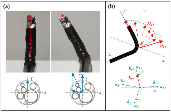 Figure 4. Schematic diagram of the orthogonal compensation method for snake bone. (a) The bending direction and angle of the distal end of the snake bone can be decomposed into two combined actions bending along the directions of the wire holes. (b) The snake bone bends within a single plane during single-wire pulling. Thus, four-directional bending corresponds to four motion planes.
 - When the snake bone bends due to the tension of multiple wires, the bending direction of the distal end of the snake bone is the resultant vector of the individual wire tensions.
Based on this assumption, the motion of the bending section’s two degrees of freedom could be decomposed into movements within four planes: , , and , corresponding to the U/D and L/R motion planes. When the distal end moved within a particular motion plane, the direction of the distal end was denoted as , forming a vector set . The least squares method could be used to estimate the motion plane. Singular value decomposition could be applied to the vector matrix:
Here, is the singular value matrix, and the column vector of the matrix corresponding to the smallest singular value represents the direction of the minimum variance of the data, which is the normal vector of the motion plane. For the four movement directions U/D and L/R, the normal vectors , , and can be calculated respectively. This allows the determination of the angles between the motion planes and the standard planes (see Figure 4b):
Here, and are the normal vectors of the standard and planes, respectively. The angles between each motion plane and the standard planes can be determined using (1) and (2). These angles represent the distribution angles of the wire hole positions in the snake bone. Assuming the target angle for the distal end’s bending (i.e., the output angle after orthogonal compensation) is , then orthogonally compensated input angles should be:
The parameters are determined by the quadrant of the target position in the standard plane:
Here, , , , represent the slopes of the projections of the respective motion planes onto the plane, while represents the slope of the projection of the desired position onto the standard plane. The orthogonally compensated input angles can be calculated using (3) and (4).
2.3. Hysteresis Compensation
Due to the presence of dead zone and backlash, further improvement in the precision of distal end position control required compensation for the nonlinear effects of the bending section. Therefore, a modified Prandtl-Ishlinskii (PI) model was employed to compensate for these nonlinear effects. The PI model described the hysteresis using a weighted sum of a series of piecewise linear envelope functions (referred to as Play operators), as illustrated in the Figure 5a. The th Play operator can be expressed as:
Here, represents the output of the th Play operator, is the system input, denotes the time sequence, and is the threshold of the operator, which is a parameter to be determined. The function is the envelope function used to describe the shape of the operator. The envelope function defined here based on the actual hysteresis curve in the form of the following piecewise function [10]:
Here, , , , , and are parameters to be determined. The final output of PI model is the weighted sum of the outputs of each Play operator:
Here, is the weight of each Play operator, which is a parameter to be determined; is the number of Play operators, and in this case, we choose to effectively characterize the model. To reduce the number of parameters to be identified, the thresholds and weights are defined as follows:
In this way, the parameters to be determined are reduced to , , and .

Figure 5.
Schematic diagram of the PI model and control process. (a) PI model schematic. (b) PI controller based on inverse PI model.
Based on the obtained forward kinematic model, the inverse PI model (see Figure 5b) can be formulated as follows:
where is the inverse function of :
and represent the threshold and weight parameters, respectively, in the inverse model:
After determining the model parameters, feedforward compensation can be performed using (9)–(11).
2.4. Contact Force Control
Previous research has indicated that in the endoscopes with TSM structures, the contact force generated torque at the distal end and the torque applied to the knobs in the control section have a relationship [14,24]:
is the proportional coefficient, and represents the internal resistance, which is the additional torque generated due to frictional forces acting on the angulation wires within the endoscope. This additional torque was influenced by both the direction and magnitude of the frictional forces. When the bending section was not in hysteresis, the direction of the frictional force remained unchanged. If the insertion section was maintained constant pose, the magnitude of the frictional force also remained constant. During this phase of motion, the torque applied to the knob gradually increased, which was the phase most prone to safety hazards. Therefore, we focused on measuring the torque during this phase of motion. According to (12), when an external contact moment is generated, the following relationship exists:
Here, represents the increment in the knob torque at a given angle. Therefore, by determining the coefficient , the magnitude of the contact moment can be quantified.
The contact force controller used the predicted torque to compare with the preset torque safety threshold. This comparison determined whether to stop the bending section from continuing its motion. The output of the contact force controller can be described as:
Here, represents the torque safety threshold. The whole control flowchart is shown in Figure 6a.
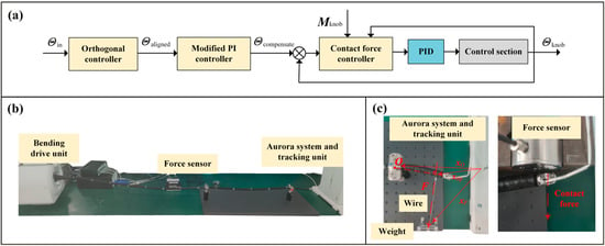
Figure 6.
Schematics of the controller and the experimental setup. (a) Diagram of control flowchart. (b) Experiment setup. (c) Illustration of contact force calibration (left) and testing of contact force safety threshold (right).
3. Results
3.1. Basic Performance
We measured the knob angle accuracy of motor-driven knobs in U/D and L/R directions, as illustrated in Figure 7a. using an input sine wave signal with a frequency of 0.05 Hz and taking the actual knob angle as the output. There were no specific studies on the response frequency of the knobs in the operating section. Considering the input frequency required for precise control by doctors during practical use, and the response capabilities of the system’s sensors, we determined that a frequency of 0.05 Hz was appropriate [10,12,25,26]. We observed maximum absolute errors (MAE) of 1.13° and 1.35° in the U/D and L/R directions, respectively. The RMSE was 0.43° for the U/D direction and 0.47° for the L/R direction.
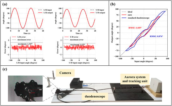
Figure 7.
Basic bending performance. (a) The input angles and the actual angles of the knob were measured during U/D and L/R movements, with the maximum errors being 1.127° and 1.347°, respectively. (b) Comparison of the hysteresis between the modified control section and the standard duodenoscope. The RMSE values were 6.685° and 9.012°, respectively. (c) Schematic of the hysteresis measurement for the standard duodenoscope.
Additionally, to compare the basic performance of the bending section, a standard duodenoscope (UHD-ED300V, Aohua Endoscope, Shanghai, China) was also tested. The knob angle was read out using a camera (shown in Figure 7c). The measured RMSE for the input-output response of the standard duodenoscope was 9.0°, whereas our device achieved an RMSE of 6.7° (see Figure 7b). It shows that the redesigned control section does not significantly increase the RMSE. However, it is also evident that the standard duodenoscope has a larger range of motion compared to our device.
3.2. Orthogonal and Hysteresis Compensation
Without orthogonal compensation, the distal end motion trajectory in the plane for U/D and L/R directions is shown in Figure 8. The deviation angles of the movement plane are calculated to be , , and . By applying the orthogonal compensator, the deviation angles were measured to be , , and . Compared to the pre-compensation values, the deviation angles decreased by 32% to 98%.
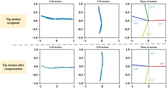
Figure 8.
Comparison before and after orthogonal compensation. The blue scatter plots represent the projection of the distal end vector during L/R and U/D movements on standard plane.
To identify the parameters of the PI model in the hysteresis compensator, a sinusoidal signal with damped attenuation is used as the input:
Here, , . The distal end output angle obtained is shown in Figure 9a. PI model parameter identification process is carried out using MATLAB R2023a, optimizing the following expression using the Levenberg-Marquardt method:
The final identified parameter results are shown in Table 1. The iteration step size was set to 10−7, and the parameters converged after 36 iterations. According to the covariance matrix, the parameter estimation variances were all less than 0.5%. The predicted model output is depicted in Figure 9a, with an RMSE of 1.25° for the U/D direction and 1.73° for the L/R direction.
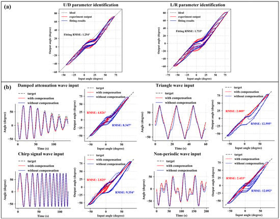
Figure 9.
Hysteresis compensation results. (a) Model parameter identification and fitting results for the U/D and L/R directions. (b) Input-output curves and hysteresis diagrams for the L/R direction under different input signals.

Table 1.
PI model parameters identification.
We used a damped attenuation wave, triangular wave, chirp signal, and non-periodic signal as L/R direction inputs to evaluate the effectiveness of the hysteresis compensation. The results are shown in Figure 9b. The RMSE values before compensation were 8.347°, 12.60°, 9.354°, and 12.09° for the respective input signals. After compensation, the RMSE values became 4.826°, 2.009°, 2.825°, and 2.433°, respectively. It can be observed that the compensation effect is significant.
Considering that in offline methods, procedural changes and instruments replacement may alter hysteresis characteristics and thus affect compensation performance [9], we also evaluated the impact of inserting common ERCP surgical instruments into the working channel. We measured the input-output RMSE using a 0.05 Hz sinusoidal signal as input with different instruments. The specific results are shown in Table 2, with all RMSE values within 3.0°, indicating that the insertion of common ERCP surgical instruments did not significantly increase the model’s error.

Table 2.
The impact on hysteresis compensation accuracy with different instruments (sinusoidal input).
3.3. Contact Force Prediction
During the contact force prediction model calibration, multiple weights were used to simulate different external contact forces. The distal end was driven in a reciprocating motion while measuring the relationship between the knob torque and the knob angle (results shown in Figure 10a). We focus on the active bending section, which is indicated by the gray dashed area. When (i.e., the mass of the weights) is 0 N, which means no contact force applied, the internal resistance can be determined according to (12) and (13):
As increases, the torque required by the knob at the same angle also increases significantly.
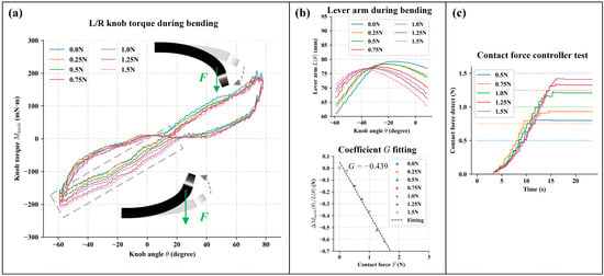
Figure 10.
The calibration and experimental results of the contact force prediction. (a) The torque of the driving motor under different contact forces. The gray area indicates the region of interest, specifically when the driving torque gradually increases with the external force generated by the load acting in opposite direction to the bending. (b) The upper figure illustrates the lever arm change during bending with different load added. The lower image shows the fitting results of coefficient . (c) The actual contact forces at the distal end under different contact force safety thresholds. The dashed line represents the preset safety threshold, while the solid represents the measured contact force.
However, due to the fixed position of the weight and the changing position of the distal end, the lever arm of the external contact force, denoted as , varied during the measurement process (shown in Figure 10b). By combining these measurements with formula (12) and (13), we obtain:
The torque transmission coefficient was calculated to be −0.439. Thus, the final expression for the contact force model is:
During the contact force prediction test, the safety thresholds were set at 0.5 N, 0.75 N, 1.0 N, 1.25 N, and 1.5 N, with . The bending drive unit will stop further bending when the model’s predicted value approached the safety threshold. The actual contact force data measured by the pressure sensor is shown in Figure 10c. It can be observed that the model is able to stop increasing the driving force when the distal end bending encounters resistance, based on different safety thresholds. When the safety threshold is low, the model’s prediction accuracy is reduced. When the safety threshold is set higher, the model’s predicted values deviate less, with an error within 25% between the set threshold and actual output contact force.
4. Discussion
During the basic performance experiment, our proposed duodenoscope structure has a knob angle maximum error of less than 1.5° and a lower RMSE in the hysteresis experiment compared to a standard duodenoscope. However, our proposed structure’s distal end motion range is smaller than that of a standard duodenoscope. Subsequently, adjustments to its range of motion will be made based on clinical needs.
Our proposed compensator reduces the deviation angle of the motion plane by 32% to 98% compared to pre-compensation, facilitating the mapping between the control platform space and the distal end motion space. After compensation, the original hysteresis characteristics are mitigated and the RMSE of the distal end output angle decreased from 8.347° to 4.826°. Further experiments showed that the presence of surgical instruments does not significantly affect the performance of the hysteresis compensator. The proposed software compensation solution is not only applicable to our designed robotic system but also suitable for other robotic systems using standard duodenoscopes. Additionally, in future system designs, we can consider using a single motor to drive a single cable end to further mitigate the dead zone effect caused by cable slacking. However, software compensation will still be necessary to overcome the effects of friction. It is noteworthy that all parameters were calibrated with the duodenoscope in a straight position, without accounting for the impact of bending in the insertion section. Studies have suggested using machine learning methods to compensate for this impact [12], which could be explored in future research.
Using the contact force prediction model, the controller can respond to different safety thresholds and stop further excessive torque applied at the distal end. The accuracy at different thresholds is within ±25% when the safety threshold is set greater than 0.75 N. However, the knob torque is indirectly measured by a torque sensor mounted on the motor base to save space, which introduces significant errors in torque measurement (as shown in Figure 10a) and affects the accuracy of contact force prediction. This issue can potentially be improved by optimizing the bending drive unit design. With more accurate torque measurement, further research could explore the interaction between the distal end pose and the applied force, enabling more precise force-position hybrid control. Additionally, while our compensation strategies and contact force models suffice for correcting distal end positions and controlling contact forces, future work should focus on accurately modeling the bending section and insertion section using continuum robot models. This direction aims to unify kinematic and mechanical models, laying the groundwork for achieving more refined automated control within the system.
5. Conclusions
The proposed structure and driving method for the duodenoscope operation section used in ERCP robotic surgery is simple and efficient. The duodenoscope features an angulation lock function that automatically maintains the distal end pose. In emergencies, a backup knob can be used for manual operation. Our proposed orthogonal and hysteresis compensation schemes require minimal computational overhead and significantly improve experimental behavior, reducing actual errors by more than half. Moreover, these software methods are not limited to this duodenoscope system alone but can also be applied to compensate for standard duodenoscopes. Additionally, the proposed contact force model for force prediction demonstrates acceptable estimates of overall behavior.
In summary, our design of the duodenoscope and control methods enables safe and precise control of the distal end, laying the foundation for our subsequent research on ERCP robotic surgery systems.
Author Contributions
Conceptualization, Y.C. and R.Y.; methodology, Y.C.; software, Y.C.; validation, Y.C., B.L., and C.Y.; formal analysis, Y.C.; investigation, Y.C. and R.Y.; resources, T.X. and B.L.; data curation, Y.C.; writing—original draft preparation, Y.C.; writing—review and editing, R.Y. and T.X.; visualization, Y.C.; supervision, T.X.; project administration, T.X.; funding acquisition, T.X. All authors have read and agreed to the published version of the manuscript.
Funding
This research was partially supported by the National Natural Science Foundation of China (82027807).
Data Availability Statement
The raw data supporting the conclusions of this article will be made available by the authors upon request.
Acknowledgments
We appreciate the technical support provided by Beijing Shuangyiqi Electronics Co., Ltd.
Conflicts of Interest
Authors B.L. and C.Y. were employed by Shanghai Aohua Photoelectricity Endoscope Co., Ltd. The remaining authors declare that the research was conducted in the absence of any commercial or financial relationships that could be construed as a potential conflict of interest.
References
- Harvin, G. Review of Musculoskeletal Injuries and Prevention in the Endoscopy Practitioner. J. Clin. Gastroenterol. 2014, 48, 590–594. [Google Scholar] [CrossRef] [PubMed]
- North, O.J.; Ristic, M.; Wadsworth, C.A.; Young, I.R.; Taylor-Robinson, S.D. Design and Evaluation of Endoscope Remote Actuator for MRI-Guided Endoscopic Retrograde Cholangio-Pancreatography (ERCP). In Proceedings of the 2012 4th IEEE RAS & EMBS International Conference on Biomedical Robotics and Biomechatronics (BioRob), Rome, Italy, 24–27 June 2012; pp. 787–792. [Google Scholar]
- Ruiter, J.; Rozeboom, E.; van der Voort, M.; Bonnema, M.; Broeders, I. Design and Evaluation of Robotic Steering of a Flexible Endoscope. In Proceedings of the 2012 4th IEEE RAS & EMBS International Conference on Biomedical Robotics and Biomechatronics (BioRob), Rome, Italy, 24–27 June 2012; pp. 761–767. [Google Scholar]
- Lee, D.-H.; Cheon, B.; Kim, J.; Kwon, D.-S. easyEndo Robotic Endoscopy System: Development and Usability Test in a Randomized Controlled Trial with Novices and Physicians. Int. J. Med. Robot. Comput. Assist. Surg. 2021, 17, e2158. [Google Scholar] [CrossRef] [PubMed]
- Eickhoff, A.; Van Dam, J.; Jakobs, R.; Kudis, V.; Hartmann, D.; Damian, U.; Weickert, U.; Schilling, D.; Riemann, J.F. Computer-Assisted Colonoscopy (The NeoGuide Endoscopy System): Results of the First Human Clinical Trial (“PACE Study”). Am. J. Gastroenterol. 2007, 102, 261–266. [Google Scholar] [CrossRef] [PubMed]
- Hwang, M.; Kwon, D. K-FLEX: A Flexible Robotic Platform for Scar-free Endoscopic Surgery. Int. J. Med. Robot. 2020, 16, e2078. [Google Scholar] [CrossRef]
- Berthet-Rayne, P.; Gras, G.; Leibrandt, K.; Wisanuvej, P.; Schmitz, A.; Seneci, C.A.; Yang, G.-Z. The i2Snake Robotic Platform for Endoscopic Surgery. Ann. Biomed. Eng. 2018, 46, 1663–1675. [Google Scholar] [CrossRef] [PubMed]
- Le, H.M.; Do, T.N.; Phee, S.J. A Survey on Actuators-Driven Surgical Robots. Sens. Actuators A Phys. 2016, 247, 323–354. [Google Scholar] [CrossRef]
- Kim, J.; de Mathelin, M.; Ikuta, K.; Kwon, D.-S. Advancement of Flexible Robot Technologies for Endoluminal Surgeries. Proc. IEEE 2022, 110, 909–931. [Google Scholar] [CrossRef]
- Song, D.; Li, J.; Zhao, J.; Zhang, G.; Wang, S.; Shi, C. Development of a Modified Generalized Prandtl–Ishlinskii Modeling and Compensation Method for Complex Hysteresis Behaviors of the Flexible Ureteroscope. IEEE Trans. Med. Robot. Bionics 2023, 5, 903–915. [Google Scholar] [CrossRef]
- Baek, D.; Seo, J.-H.; Kim, J.; Kwon, D.-S. Hysteresis Compensator With Learning-Based Hybrid Joint Angle Estimation for Flexible Surgery Robots. IEEE Robot. Autom. Lett. 2020, 5, 6837–6844. [Google Scholar] [CrossRef]
- Lee, D.-G.; Baek, D.; Kim, H.; Kim, J.; Kwon, D.-S. Learning-Based Discrete Hysteresis Classifier Using Wire Tension and Compensator for Flexible Endoscopic Surgery Robots. Int. J. Precis. Eng. Manuf. 2023, 24, 83–94. [Google Scholar] [CrossRef]
- Cursi, F.; Bai, W.; Yeatman, E.M.; Kormushev, P. Model Learning With Backlash Compensation for a Tendon-Driven Surgical Robot. IEEE Robot. Autom. Lett. 2022, 7, 7958–7965. [Google Scholar] [CrossRef]
- Zhang, A.; Han, Z.; Wang, X.; Briggs, R.; Xie, T. Mixed Control Scheme for Accurate Control of Robotic Flexible Endoscope. Int. J. Adv. Robot. Syst. 2017, 14, 1729881417702506. [Google Scholar] [CrossRef]
- Zhou, Y.; Jiang, G.; Zhang, C.; Wang, Z.; Zhang, Z.; Liu, H. Modeling of a Joint-Type Flexible Endoscope Based on Elastic Deformation and Internal Friction. Adv. Robot. 2019, 33, 985–995. [Google Scholar] [CrossRef]
- Li, Z.; Shan, J.; Gabbert, U. A Direct Inverse Model for Hysteresis Compensation. IEEE Trans. Ind. Electron. 2021, 68, 4173–4181. [Google Scholar] [CrossRef]
- Dupont, P.E.; Simaan, N.; Choset, H.; Rucker, C. Continuum Robots for Medical Interventions. Proc. IEEE 2022, 110, 847–870. [Google Scholar] [CrossRef] [PubMed]
- Russo, M.; Sadati, S.M.H.; Dong, X.; Mohammad, A.; Walker, I.D.; Bergeles, C.; Xu, K.; Axinte, D.A. Continuum Robots: An Overview. Adv. Intell. Syst. 2023, 5, 2200367. [Google Scholar] [CrossRef]
- Ryu, H.-T.; Kang, L.; Yi, B.-J. Application of Cosserat Rod Theory to Configuration Estimation of Coionoscope. In Proceedings of the 2018 15th International Conference on Ubiquitous Robots (UR), Honolulu, HI, USA, 26–30 June 2018; pp. 11–13. [Google Scholar]
- Isbister, A.; Bailey, N.Y.; Georgilas, I. An Integrated Kinematic Modeling and Experimental Approach for an Active Endoscope. Front. Robot. AI 2021, 8, 667205. [Google Scholar] [CrossRef]
- Burgner-Kahrs, J.; Rucker, D.C.; Choset, H. Continuum Robots for Medical Applications: A Survey. IEEE Trans. Robot. 2015, 31, 1261–1280. [Google Scholar] [CrossRef]
- Schneider, J.; Duckworth-Mothes, B.; Schweizer, U.; Königsrainer, A.; Fisch, J.; Wichmann, D. Exerting Forces and Wall Load during Duodenoscopy for ERCP: An Experimental Measurement in an Artificial Model. Bioengineering 2023, 10, 523. [Google Scholar] [CrossRef]
- Takano, S.; Fukasawa, M.; Shindo, H.; Takahashi, E.; Hirose, S.; Fukasawa, Y.; Kawakami, S.; Hayakawa, H.; Yokomichi, H.; Kadokura, M.; et al. Risk Factors for Perforation during Endoscopic Retrograde Cholangiopancreatography in Post-Reconstruction Intestinal Tract. World J. Clin. Cases 2019, 7, 10–18. [Google Scholar] [CrossRef]
- Xie, Y.; Hou, X.; Liu, H.; Housden, J.; Rhode, K.; Hou, Z.-G.; Wang, S. Contact Force Prediction for a Robotic Transesophageal Ultrasound Probe via Operating Torque Sensing. In Proceedings of the Simplifying Medical Ultrasound; Aylward, S., Noble, J.A., Hu, Y., Lee, S.-L., Baum, Z., Min, Z., Eds.; Springer International Publishing: Cham, Switzerland, 2022; pp. 152–161. [Google Scholar]
- Lee, D.-H.; Kim, Y.-H.; Collins, J.; Kapoor, A.; Kwon, D.-S.; Mansi, T. Non-Linear Hysteresis Compensation of a Tendon-Sheath-Driven Robotic Manipulator Using Motor Current. IEEE Robot. Autom. Lett. 2021, 6, 1224–1231. [Google Scholar] [CrossRef]
- Legrand, J.; Javaux, A.; Ourak, M.; Wenmakers, D.; Vercauteren, T.; Deprest, J.; Ourselin, S.; Denis, K.; Vander Poorten, E. Handheld Active Add-On Control Unit for a Cable-Driven Flexible Endoscope. Front. Robot. AI 2019, 6, 87. [Google Scholar] [CrossRef] [PubMed]
Disclaimer/Publisher’s Note: The statements, opinions and data contained in all publications are solely those of the individual author(s) and contributor(s) and not of MDPI and/or the editor(s). MDPI and/or the editor(s) disclaim responsibility for any injury to people or property resulting from any ideas, methods, instructions or products referred to in the content. |
© 2024 by the authors. Licensee MDPI, Basel, Switzerland. This article is an open access article distributed under the terms and conditions of the Creative Commons Attribution (CC BY) license (https://creativecommons.org/licenses/by/4.0/).