Abstract
With improvements in lubrication and material strength, the power transmitted by plastic gears has increased significantly. To develop high-performance transmission systems, it is necessary to gain deep insights into the dynamic characteristics of plastic gears. However, because plastics are viscoelastic materials, they do not obey Hooke’s law, which is the basis of traditional gear dynamic models. In this study, a refined dynamic model for an epoxy gear pair considering material viscoelasticity and extended tooth contact is established, and the differences in the dynamic responses between an epoxy and a steel gear pair are compared with respect to the dynamic meshing force and dynamic transmission error. The results show that: (1) the plastic gear can restrain the meshing impact, it has a generally lower dynamic meshing force than steel gear pair; (2) the position accuracy is the weak point of plastic gears, and this is significantly affected by the rotation speed; (3) the way to indirectly evaluate the dynamic meshing force by measuring the dynamic transmission error, which is often used for metal gears and is less effective for plastic gears.
1. Introduction
Plastic gears, which offer the advantages of self-lubrication, light weight, and mass production by injection molding, are extensively used in various low-load-transmission applications in home appliances, instrumentation devices, office equipment, and medical devices. Lately, designers have expanded the application scenarios for plastic gears that accommodate greater loads further by using novel additives and substituting dry contact with oil-lubricated contact [1,2]. Hasl et al. [3] from the Gear Research Center at the Technical University of Munich tested the load-carrying capacity of injection-molded polyacetal gears under oil-lubricated conditions. They found that the power transmitted by these gears could be raised to as high as 30 kW, meeting the power requirements of compact city vehicles. As the transmitted power increased, the vibration and noise generated by the plastic gears rose accordingly, resulting in enormous attention from scholars [4]. The investigation of plastic gear dynamics has contributed significantly to revealing their functional behavior and led to improvements in the characteristics of plastic gears in the power transmission field.
As transmission errors are a significant source of unwanted vibration and noise in gear drives [5], many scholars have studied transmission errors involving plastic gears. For example, Tsai et al. [6] and Karimpour et al. [7] simulated the static transmission error (STE) of plastic gears using the finite element method. They pointed out that extended tooth contact, owing to low tooth stiffness in plastic gears, could be observed, which resulted in notable differences in the STE between plastic and metal gears. Similarly, Meuleman et al. [8] modelled the plastic gear teeth using beam elements to investigate the influences of material types, contact ratios, and pressure angles of the drive- and driven-gears on the plastic gear pairs’ STE. They subsequently proposed design principles to reduce these STE fluctuations. Nonetheless, employing the STE as an indicator of system excitation can only help to accurately predict the dynamics of nearly pure torsional gear pairs [5]. The actual system excitation cannot be denoted by the pre-calculated STE when tooth separation and back-side contact occur in gear pairs. Consequently, scholars developed a dynamic model for plastic gears based on their instantaneous mesh state. Atanasiu et al. [9] calculated the mesh stiffness per unit of contact length using the potential deformation energy method and established a torsional dynamic model of steel/plastic helical gear pairs using the time-varying contact length during engagement. Then, the dynamic mesh force (DMF) and dynamic transmission error (DTE) of the steel/plastic gear pair during its operation were analyzed. Lin et al. [10] established a torsional dynamic model for plastic gears which considers the temperature effects on plastic material, then the distributions and variations of bending and surface contact stresses around the fillet and contacting points are investigated. Subsequently, they proceeded to investigate the interaction between the dynamic contact load and the tooth profile wear of engaged plastic gear pairs by coupling the tooth wear equation in the dynamic model for plastic gears [11]. Duan et al. [12] established a torsional dynamic model for the planetary gear set, and comparatively investigated the patterns of dynamic load when the sun, planet, and ring gears are replaced with plastic gears, respectively. Notably, in the aforementioned studies, the plastics have been treated as elastomers [6,7,8,9,10,11,12] and the dynamic properties of the plastic gears have been approximated by modifying the mesh stiffness and mass density using the traditional dynamic model for metal gears. In contrast, viscoelastic plastics can undergo significant creep and relaxation, and their constitutive models are entirely different from those of metallic materials [13]. Guingand et al. [14,15,16] from the Institut National des Sciences Appliquées established a load-sharing model that considered the viscoelastic properties of the plastics and investigated the mechanical behavior of plastic cylindrical gears made of polymeric material through numerical and experimental studies. However, the load sharing model was quasi-static and did not consider the corner contact caused by the significant plastic gear tooth deformations.
In summary, the dynamic modeling and analysis of plastic gears await further investigation. This study proposes a refined dynamic model for plastic gears considering material viscoelasticity and extended tooth contact, and reveals the differences in dynamic responses between the epoxy gear pair and steel gear pair. The research results can provide theoretical support for the design of high-performance plastic gear transmission systems.
2. Modeling Approach
2.1. Viscoelasticity Description
The linear viscoelastic properties of plastics can be deduced from relaxation tests. When subjected to constant strain, plastics produce a gradually decreasing stress. The temporal evolution of the reaction stress provides the material’s relaxation modulus , a time varying ratio of stress over strain. This modulus can be expressed by rheological models that introduce the so-called retardation times, roughly the time scale of the material’s response. Usually, a single retardation time is insufficient to describe the viscoelasticity of plastic, and the relaxation modulus can be expressed as:
where is the instantaneous modulus, is the statistical weight, is retardation time, and they are all material constants.
2.2. Formulation of Plastic Tooth Force
2.2.1. Mechanical Model of the Plastic Gear Tooth
To establish the plastic gear dynamic model, it is necessary to define the force–deformation relation of the plastic tooth. In the case of metal gears, the tooth stiffness is introduced as the ratio of tooth force over tooth deformation. The tooth stiffness can be calculated using an analytical method in which the gear tooth is considered as a nonuniform cantilever beam and the tooth stiffness consists of five parts:
where , , , , and are the shear stiffness, bending stiffness, axial compressive stiffness, Hertzian contact stiffness, and fillet-foundation stiffness, respectively. The other symbols in Equation (2) have been discussed thoroughly in reference [17]. Because the integral values in Equation (2) are determined by the tooth geometry and are independent of the material’s properties, it is possible to rewrite the relation between tooth stiffness and material modulus with the geometric influence coefficient as follows:
In the case of the plastic gear, a relaxation stiffness can be introduced through the relaxation modulus. In this method, the relaxation stiffness is defined as the time-dependent force output corresponding to a constant deformation input that can be calculated by combining expressions (1) and (2) to.
where is the instantaneous tooth stiffness, and and have the same values as in Equation (1). Equation (4) represents the viscoelastic properties of plastic gear tooth deformation in the form of a Prony series. The exponential Prony series is particularly popular as it enables the use of a recursive algorithm for a fast and easy solution of the convolution integral constitutive law. However, to couple the relaxation tooth stiffness model with the gear dynamic model, the viscoelastic properties of the plastic tooth should be converted from the Prony series form to the differential form as in the following Equations (5)–(7), whose topological structure is shown in Figure 1 [13].
where is the tooth deflection, is a derivative of , is the tooth force, and , , and can be calculated from , , and , respectively, using the following expressions [13]:
where is the same as in Equation (4) and and are the same as in Equation (1).
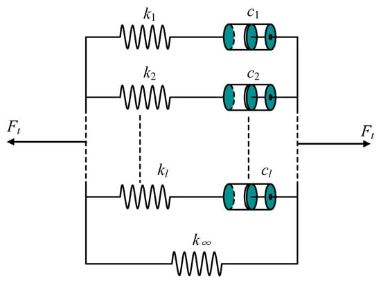
Figure 1.
Mechanical model of plastic gear tooth.
2.2.2. Tooth Deflection Considering the Extended Tooth Contact Effect
As plastic gears have a relatively low modulus, the tooth deflections can be large compared to those experienced by metal gears. Further, the flexibility of non-metallic gears allows for gear tooth contact outside the theoretical line of action. Figure 2 shows the mesh analysis model of a spur gear pair without tooth modification, where 1 is the driving gear, 2 is the driven gear, and is the base radius of gear j. The generalized displacement of the gear pair can be expressed as:
where (j = 1, 2) is the translational displacement of gear j relative to its initial position; is the angular displacement of gear j relative to taken as the initial position and is positive in the rotational direction of gears, i.e., values are more than zero.
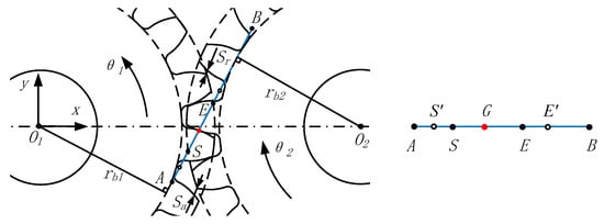
Figure 2.
Meshing analysis of spur gear.
As shown in Figure 2, is the theoretical region of engagement without consideration of tooth deformations, and is the actual region of engagement with consideration of tooth deformations. As and are load-related points, using as the mesh analysis region will cause much inconvenience. Therefore, with a fixed length is selected as the mesh analysis region based on the principle of ensuring in this study. The following is a brief description of the method employed in this study. Let point precede point and ; let point follow point and ; where is the base pitch, is the minimum integer of value not less than , and is the contact ratio. includes three subregions: the determination region of early approach , the theoretical region of engagement , and the determination region of retarded recess . is the intersection point of the driving gear tooth profile (or its extension) on , and is a periodic function of the angular displacement expressed as:
where is the remainder function and the range of is .
The computational equation for total deformation of the tooth pair along the line of action in the three subregions of is discussed in two cases without considering the tooth back-side contact.
- (1)
- When G lies on the SE:
- (2)
- When G lies outside the SE, the total deformation of the gear teeth along the line of action is determined by subtracting the primary clearance from the theoretical deformation due to the presence of the primary clearance.
According to the geometric analysis, the first-order derivative of is given by:
where is the Heaviside step function; when , then , otherwise .
2.3. Plastic Gear Pair Dynamic Model Considering Material Viscoelasticity and Extended Tooth Contact
In Section 2.2, the computational method for the meshing force of a single pair of gear teeth at different regions of the line of action was derived (Equations (5)–(7) and (13)–(16)). Here, we derive the computational method for the meshing force when multiple pairs of gear teeth are engaged sequentially. Although the plastic gear tooth deformation requires a certain amount of time to be restored after the load is removed, the time is shorter than ten times the loading time [19]. Therefore, when the tooth numbers of the driving and driven gears are more than 10, the gear tooth deformations can be considered as zero prior to the next engagement, regardless of the gear tooth deformations at the present engagement. As is the spacing between adjacent intersection point on and the range of is , there are, in total, intersection points on . Table 1 shows that the contact ratio of the study case (i.e., spur gear pair) is 1.69, thus . This means that there are three intersection points on that are sequentially denoted by () (Figure 3). At time , the spacing between point and point is expressed as:

Table 1.
Basic parameters of spur gear pair.
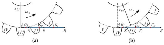
Figure 3.
Gear mesh analysis, t1 < t2: (a) t1 (b) t2.
When the angular displacement of the driving gear increases, the value of () periodically varies from small to large value in the interval , representing the left-to-right cyclic motion of on .
Based on the above analysis of the engagement process, the continuous excitation of the tooth pair on the line of action during the continuous gear drive can be determined by substituting Equation (17) into Equations (13)–(16). Using the basic dynamic modeling approach of gears [20], a six-degree-of-freedom model of a pair of spur gear pairs is established as follows:
where is the generalized system mass matrix, () is the mass of gear , is the moment of inertia of gear j, and is the diagonal matrix with taken as the diagonal elements; and are the damping and stiffness matrices of the bearing system, respectively, and are the bearing damping of the gear in the and directions, respectively, and and are the corresponding bearing stiffnesses, respectively; is the generalized displacement of the gear pair and its six degrees of freedom are shown in Equation (11); is the system load vector, is structure vector depending on gear geometry; is the sum of the mesh forces of all tooth pairs on ; is the ith meshing force component of the kth tooth pair. Different from the algebraic form meshing force formula of the metal gear, the meshing force component of the plastic gear is in the form of differential equation. The function in Equation (20) essentially includes Equations (5)–(7) and (13)–(17).
3. Simulation Results and Discussion
3.1. Model Settings and Validation
Taking a certain type of pre-developed four-seat electric sightseeing vehicle as an example, it is driven by a two-stage gear reducer with a total ratio of 6.56. To reduce the cost, a plastic gear is proposed to be used in the high-speed stage. It is known that the total mass of the vehicle is 890 kg, the power of the drive motor is 4 kW, the input torque of high-speed stage is 19.1 N·m, the input speed of high-speed stage is 2000 r/min, and the gear parameters are shown in Table 1. In order to reveal the influences of material viscoelasticity on the dynamic behavior of the gears, plastic and metal gear pairs with the same basic parameters are selected for comparative study in this paper. The obtained conclusions can give guidance to the selection of dynamic modeling methods for plastic gears. In this study, the plastic gear is made of epoxy with a density of 1180 kg/m3, and more viscoelastic parameters are shown in Table 2. The metal gear is made of carburizing and quenching heat-treatment carbon steels, which have a density of 7850 kg/m3, a Young’s modulus of 209 GPa, and a Poisson’s ratio of 0.3.
Table 2.
Prony series parameters for epoxy [21].
The three-dimensional finite element model of the spur gear is established using Abaqus (Figure 4a) based on the hexahedral element C3D8R. The geometric parameters of the gear pair are shown in Table 1. The single tooth meshing state is taken for analysis, and the unloaded gear teeth are omitted to reduce the number of elements (there are 29,120 elements and 34,912 nodes in total). Subsequently, a constant load of 20 N·m is applied to the finite element model, and the gear materials are set as carbon steels and epoxy, respectively. The tooth deformations along the line of action are obtained as shown in Figure 4b,c. The results show that the tooth deformation of the steel gear pair does not change with time (Figure 4b), while that of the epoxy gear pair increases with time (Figure 4c). As a validation, the calculation results of the proposed theoretical model and the finite element model are compared and agree well with each other (Figure 4c). Table 3 shows the employed stiffness and damping parameters in the mechanical model during the case calculations.
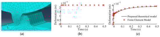
Figure 4.
Tooth deformation analysis of steel and epoxy gear: (a) finite element model; (b) tooth deformation of steel gear pair; (c) tooth deformation of epoxy gear pair.
Table 3.
Basic parameters of mechanical model (Figure 1) for epoxy gear.
3.2. Frequency-Dependent Tooth Force
As shown in Figure 5a, a pulse deformation with period of 2 and duty cycle of 50% is applied to the mesh force model of the gear teeth (Equation (6)). Figure 5b,c show the curves of the output gear tooth forces at different deformation frequencies. The gear tooth force is markedly attenuated (i.e., relaxation is obvious) at a low deformation frequency in the deformation holding process (Figure 5b), while the relaxation is not obvious at a high deformation frequency during the deformation holding process (Figure 5c). This suggests that the tooth force of the epoxy gear approximates to that of the steel gear when deformation is excited at a high frequency.
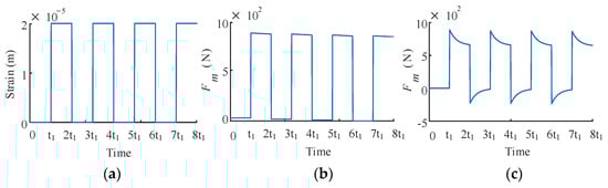
Figure 5.
Frequency-dependent tooth force: (a) gear tooth deformation; (b) response of the tooth force when t1 = 3τ1; (c) response of the tooth force when t1 = 0.05τ1.
3.3. Dynamic Load Factor
Although the speed range of the prototype motor is 0–2000 r/min, the rated motor speeds of the same type of vehicles in the market are different. In addition, the motor parameters may be reselected in the subsequent development. Therefore, as basic theoretical research, this study expands the speed range to 0–5000 r/min during the analysis. The speed of 5000 r/min is selected as the upper limit because such vehicles rarely use high-speed motors due to cost reasons. Figure 6 shows the dynamic load factors of the epoxy and steel gear pairs in the range of 0–5000 r/min. The dynamic load factor is defined as follows [22]:
where is the maximum DMF and is the maximum static mesh force. Figure 6 shows that the of the epoxy gear pair is lower than that of the steel gear pair at comparatively lower speeds (e.g., less than 900 r/min). Additionally, the curve of the epoxy gear pair climbs slowly and shows no obvious peak–trough characteristics at a low speed, whereas the curve of the steel gear pair ascends quickly with the rotational speed and then fluctuates to form multiple obvious peak–trough structures. This is attributed to the fact that the viscoelasticity of plastics helps to inhibit the DMF of the gears, yet the inhibitory effect decreases with increasing rotational speed (see Section 3.2). Therefore, epoxy and steel gear pairs show similar curve shapes of and multiple peak–trough structures at comparatively higher rotational speeds (e.g., more than 1000 r/min), yet the peak of the steel gear pair is greater than that of the epoxy gear pair.
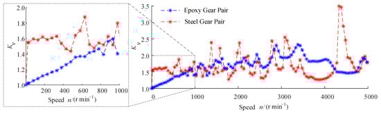
Figure 6.
Comparison of Kv between epoxy gear pair and steel gear pair.
After obtaining the maximum , the DMFs of the epoxy and steel gear pairs are taken for further analysis. Figure 7a,b show the simulated DMFs of the epoxy gear pair at 3380 r/min in the time and frequency domains, respectively. In the time domain, the epoxy gear pair is impacted by approach and recess actions, the DMF fluctuates periodically, and tooth separation does not occur. In the frequency domain, the major components of DMF are the mesh frequency (1300 Hz) and its multiple frequencies, and the maximum amplitude occurs at the 6-fold mesh frequency. Figure 7c,d show the simulated DMFs of the steel gear pair at 4330 r/min in the time and frequency domains, respectively. In the time domain, the minimum DMF of the steel gear pair is zero, thereby suggesting that instantaneous tooth separation occurs during gear drive and the drive quality deteriorates. In the frequency domain, the primary components of DMF are mesh frequency (1659.8 Hz) and its multiple frequencies, and the maximum amplitude occurs at the 2-fold mesh frequency. A comparison between Figure 7b,d suggests that the DMF of the steel gear pair shows more sideband components near the mesh frequency and its multiple frequencies, whereas the DMF of the epoxy gear pair shows fewer sideband components.
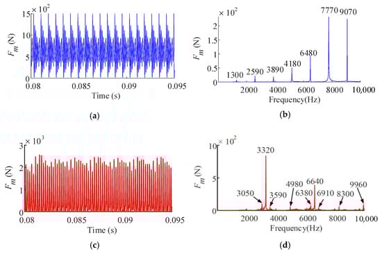
Figure 7.
Comparison of dynamic mesh force: (a) time domain of epoxy gear pair, 3380 r/min; (b) frequency domain of epoxy gear pair; (c) time domain of steel gear pair, 4330 r/min; (d) frequency domain of steel gear pair.
3.4. Dynamic Transmission Error Factor
Because the meshing stiffnesses of the epoxy gear and the steel gear are quite different, it is inconvenient to directly compare their dynamic transmission errors. To facilitate the analysis of the variation of characteristics of dynamic transmission error with rotational speed, the dynamic transmission error factor is defined by reference to the definition of the as follows:
where is the maximum DTE and is the maximum static transmission error. As shown in Figure 8a, the curve of the epoxy gear pair decreases rapidly and then flattens out in the range of 1–250 r/min. Figure 8b shows the DTEs of the epoxy gear pair at different rotational speeds, and it can be seen that there is an obvious creep phenomenon at low speeds. With the increase of speed, the creep deformation decreases gradually, i.e., the peak value of DTE decreases gradually. Furthermore, when the rotational speed exceeds a certain value, the peak value of DTE decreases very slowly.
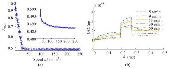
Figure 8.
Dynamic response of epoxy gear pair: (a) Kv; (b) DTEs.
As shown in Figure 9, when the rotational speed continues to rise, the curve of the epoxy gear pair generally shows a marginally decreasing trend and multiple peak–trough structures. Specifically, the overall decreasing trend occurs as a result of the shortened creep time of the epoxy gear tooth, and the nonlinear dynamic behavior of the gear pair gives rise to the peak–trough structures. Additionally, the curve of the epoxy and steel gear pairs are noticeably different—namely, the former is less than 1 while the latter is greater than 1. This signifies that the DTE of the epoxy gear pair is lower than its STE when the creep behavior and mesh excitation are considered simultaneously, whereas the DTE of the steel gear pair is greater than its STE because of the absence of creep.
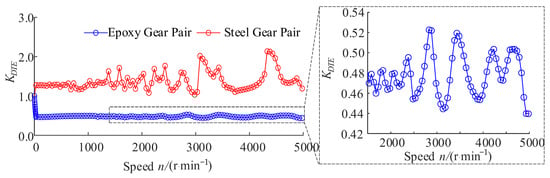
Figure 9.
Comparison of KDTE between the epoxy gear pair and the steel gear pair.
3.5. Relations between Kv and KDTE
As shown in Figure 10, the variation trends in the and of the steel gear pair are basically identical, indicating a good linear correlation. This phenomenon is consistent with the findings reached by Hotait [23] through experimental tests. In contrast, the of the epoxy gear pair shows poor linear correlation with its (Figure 11a). For instance, at nearly 4300 r/min, the curve of the epoxy gear pair peaks, thereby demonstrating that the DMF is a local maximum value; a trough appears on the curve, thereby indicating that the DTE is a local minimum value. Additionally, as highlighted by the red rectangle in Figure 11a, the in this region shows an upward trend, while the shows a downward trend. To reveal the causes of this phenomenon, further inspections were done at 3980 r/min and 4280 r/min. As shown in Figure 11b, with the increase of rotational speed, the peak value of the DTE of the plastic gear pair increases, which will cause the increase of the meshing force component in Equation (7). However, as shown in Figure 11c, with the increase of rotational speed, the absolute value of the derivative of DTE decreases, which will cause the decrease of meshing force component () in Equation (7). Finally, although the dynamic transmission error increases, the dynamic meshing force decreases.
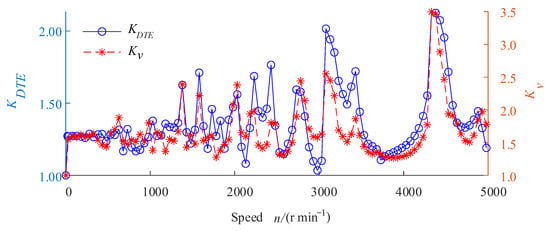
Figure 10.
Relations between Kv and KDTE for the steel gear pair.
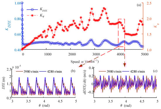
Figure 11.
Relations between Kv and KDTE for epoxy gear pair: (a) comparison Kv of KDTE; (b) DTEs; (c) derivative of DTEs.
4. Conclusions
Because plastic gears have the advantages of self-lubrication, light weight, and high production efficiency, they are widely used to transmit power as a replacement for metal gears. However, when loaded, plastics have different deformation rules than metals, which can affect the gear dynamics. In this study, the dynamic characteristics of epoxy and steel gear pairs with the same basic parameters are systematically compared under the same working conditions. The main conclusions are described below.
- 1.
- The dynamic load factor () of the epoxy gear pair is smaller than that of the steel gear pair at low rotational speeds. With increased rotational speeds, both gear pairs’ curves show some peaks and valleys. However, the rotational speeds corresponding to the peak values of the different gear pairs’ curves are different, and the maximum of the epoxy gear pair is smaller than that of the steel gear pair. This means that the plastic gear can restrain the meshing impact, and it has a generally lower dynamic meshing force than the steel gear pair.
- 2.
- The dynamic transmission error factor () of the epoxy gear pair is less than one, while the of the steel gear pair is greater than one. Specifically, the of the epoxy gear pair decreases rapidly with the increase of the rotational speed at low speeds. In contrast, it decreases slowly with weak peak–valley characteristics at high speeds. However, the of the steel gear pair shows obvious peak–valley characteristics in the whole speed range. This means that the position accuracy is the weak point of plastic gears, and this feature is significantly affected by the speed, especially when the operating speed is low.
- 3.
- The of the epoxy gear pair has poor correlation with its , whereas the of the steel gear pair has good correlation with its . This means that the way to indirectly evaluate the dynamic meshing force by measuring the dynamic transmission error, which is often used for metal gears, is less effective for plastic gears.
Author Contributions
Conceptualization, H.J. and X.X.; methodology, H.J. and J.Z.; software, J.Z.; validation, J.Z. and H.J.; formal analysis, J.Z. and H.J.; investigation, J.Z. and H.J.; resources, J.Z.; writing—original draft preparation, J.Z.; writing—review and editing, H.J. and X.X.; supervision, H.J.; project administration, H.J. All authors have read and agreed to the published version of the manuscript.
Funding
This research was funded by Chongqing Key Laboratory for Public Transportation Equipment Design and System Integration Open Fund (CKLPTEDSI-KFKT-202109), Foundation of National Natural Science of China (51975078), the Chongqing Science Fund for Distinguished Young Scholars (cstc2021jcyj-jqX0010), the Foundation of the Chongqing Basic Research and Frontier Exploration Project (cstc2022ycjh-bgzxm0130).
Acknowledgments
The authors would like thank Ningbo Hawk Electrical Appliance Co., Ltd. for their support via the postdoctoral program.
Conflicts of Interest
The authors declare no conflict of interest.
Nomenclature
| α | pressure angle |
| δk | sum of normal deformation of tooth pair k |
| ε | material strain |
| εα | theoretical profile contact ratio (without tooth modification) |
| δ | material stress |
| τi | retardation time for viscoelastic material |
| ∆1, ∆2 | deformation component of standard linear solid model |
| b | tooth width |
| ci | damping component of viscoelastic gear tooth model |
| cjx, cjy | bearing damping of the gear j in the x and y directions |
| gi | statistical weight of viscoelastic material’s Prony series |
| ki | stiffness component of viscoelastic gear tooth model |
| k∞ | stiffness component of viscoelastic gear tooth model |
| kjx, kjy | bearing stiffnesses of the gear j in the x and y directions |
| m | gear module |
| mj | mass of gear j |
| pb | base circle pitch |
| rb | base circle radius |
| t | time |
| Cg | geometric influence coefficient connecting gear tooth stiffness K and material elastic modulus E |
| E | material elastic modulus |
| Fm | total meshing force of gear pair (one or more tooth pairs) |
| Ft | meshing force for single tooth pair |
| Jj | moment of inertia of gear j |
| K | linear displacement stiffness of gear teeth along the line of action |
| K0 | instantaneous tooth stiffness |
| Ka | tooth axial compressive stiffness |
| Kb | tooth bending stiffness |
| Kf | fillet-foundation stiffness of tooth |
| Kh | Hertzian contact stiffness of tooth |
| Ks | tooth shear stiffness |
| Kv | dynamic load factor |
| KDTE | dynamic transmission error factor |
| Sa | primary clearances of the tooth pair in the region of the early approach |
| Sr | primary clearances of the tooth pair in the region of the retarded recess |
| Zj | tooth number of gear j |
References
- Afifi, E.M.; Elshalakny, A.B.; Osman, T.A.; Kamel, B.M.; Zian, H. Investigation of gear performance of MLNGPs as an additive on polyamide 6 spur gear. Fuller. Nano-Tubes Carbon Nanostruct. 2018, 26, 351–359. [Google Scholar] [CrossRef]
- Yu, G.; Liu, H.; Mao, K.; Zhu, C.; Lu, Z. Examination on the wear process of polyformaldehyde gears under dry and lubricated conditions. Friction 2021, 9, 538–550. [Google Scholar] [CrossRef]
- Hasl, C.; Illenberger, C.; Oster, P.; Tobie, T.; Stahl, K. Potential of oil-lubricated cylindrical plastic gears. J. Adv. Mech. Des. Syst. Manuf. 2018, 12, 17–26. [Google Scholar] [CrossRef]
- Hoskins, T.; Dearn, K.; Kukureka, S.N.; Walton, D. Acoustic noise from polymer gears—A tribological investigation. Mater. Des. 2011, 32, 3509–3515. [Google Scholar] [CrossRef]
- Velex, P.; Ajmi, M. On the modelling of excitations in geared systems by transmission errors. J. Sound Vib. 2006, 290, 882–909. [Google Scholar] [CrossRef]
- Tsai, M.H.; Tsai, Y.C. A method for calculating static transmission errors of plastic spur gears using FEM evaluation. Finite Elem. Anal. Des. 1997, 27, 345–357. [Google Scholar] [CrossRef]
- Karimpour, M.; Dearn, K.D.; Walton, D. A kinematic analysis of meshing polymer gear teeth. Proc. Inst. Mech. Eng. Part L J. Mater. Des. Appl. 2010, 224, 101–115. [Google Scholar] [CrossRef]
- Meuleman, P.K.; Walton, D.; Dearn, K.D.; Weale, D.J.; Driessen, I. Minimization of transmission errors in highly loaded plastic gear trains. Arch. Proc. Inst. Mech. Eng. Part C J. Mech. Eng. Sci. 2007, 221, 1117–1129. [Google Scholar] [CrossRef]
- Atanasiu, V.; Doroftei, I.; Iacob, M.R.; Leohchi, D. Nonlinear Dynamics of Steel/Plastic Gears of Servomechanism Structures. Mater. Plast. 2011, 48, 98–103. [Google Scholar]
- Lin, A.D.; Kuang, J.H. The Bending and Surface Contact Stress Variations in a Mating Plastic Gear Pair. In Proceedings of the ASME International Design Engineering Technical Conferences and Computers and Information in Engineering Conference, Las Vegas, NV, USA, 4–7 September 2007; pp. 263–271. [Google Scholar]
- Lin, A.D.; Kuang, J.H. Dynamic interaction between contact loads and tooth wear of engaged plastic gear pairs. Int. J. Mech. Sci. 2008, 50, 205–213. [Google Scholar] [CrossRef]
- Duan, F.; Hu, Q.; Xie, C. Vibration characteristics of steel/plastic gear combined planetary transmission. J. Mech. Eng. 2010, 46, 62–67. [Google Scholar] [CrossRef]
- Brinson, H.F.; Brinson, L.C. Polymer Engineering Science and Viscoelasticity: An Introduction, 2nd ed.; Springer: New York, NY, USA, 2015. [Google Scholar]
- Letzelter, E.; de Vaujany, J.P.; Chazeau, L.; Guingand, M. Quasi-static load sharing model in the case of Nylon 6/6 cylindrical gears. Mater. Des. 2009, 30, 4360–4368. [Google Scholar] [CrossRef]
- Cathelin, J.; Letzelter, E.; Guingand, M. Experimental and Numerical Study of a Loaded Cylindrical PA66 Gear. J. Mech. Des. 2013, 135, 041007. [Google Scholar] [CrossRef]
- Cathelin, J.; Guingand, M.; Vaujany, J.-P. Experimental and numerical study of a loaded cylindrical glass fibre reinforced PA6 gear. In Proceedings of the 2014 International Gear Conference, Lyon, France, 26–28 August 2014; pp. 138–147. [Google Scholar]
- Chen, Z.; Shao, Y. Dynamic simulation of spur gear with tooth root crack propagating along tooth width and crack depth. Eng. Fail. Anal. 2011, 18, 2149–2164. [Google Scholar] [CrossRef]
- Lin, H.; Wang, J.; Oswald, F.B.; Coy, J. Effect of extended tooth contact on the modeling of spur gear transmissions. Gear Technol. 1994, 11, 18–25. [Google Scholar]
- Vuoristo, T.; Kuokkala, V.-T. Creep, recovery and high strain rate response of soft roll cover materials. Mater. Des. 2002, 34, 493–504. [Google Scholar] [CrossRef]
- Qin, D.; Jia, H. Hybrid dynamic modeling of shearer’s drum driving system and the influence of housing topological optimization on the dynamic characteristics of gears. J. Adv. Mech. Des. Syst. Manuf. 2018, 12, 17–00457. [Google Scholar] [CrossRef]
- Liu, Z.; Oswald, J.; Belytschko, T. XFEM modeling of ultrasonic wave propagation in polymer matrix particulate/fibrous composites. Wave Motion 2013, 50, 389–401. [Google Scholar] [CrossRef]
- Bruyère, J.; Gu, X.; Velex, P. On the analytical definition of profile modifications minimising transmission error variations in narrow-faced spur and helical gears. Mech. Mach. Theory 2015, 92, 257–272. [Google Scholar] [CrossRef]
- Hotait, M.A.; Kahraman, A. Experiments on the relationship between the dynamic transmission error and the dynamic stress factor of spur gear pairs. Manuf. Technol. Mach. Tool 2013, 70, 116–128. [Google Scholar] [CrossRef]


Disclaimer/Publisher’s Note: The statements, opinions and data contained in all publications are solely those of the individual author(s) and contributor(s) and not of MDPI and/or the editor(s). MDPI and/or the editor(s) disclaim responsibility for any injury to people or property resulting from any ideas, methods, instructions or products referred to in the content. |
© 2023 by the authors. Licensee MDPI, Basel, Switzerland. This article is an open access article distributed under the terms and conditions of the Creative Commons Attribution (CC BY) license (https://creativecommons.org/licenses/by/4.0/).