Abstract
Since the clearance between the guide rail and the roller reduces the efficiency of the 2D pump, this paper proposes a novel 2D piston pump with stacked taper roller sets to eliminate the effect of the clearance. The structure of the 2D pump is introduced, and the mathematical model of the torque and the mechanical efficiency of the bilateral force on the guide rail are established and analyzed. The model takes into account the change in the oil viscosity, the spatial angle and the oil churning loss. A test rig was built to test the mechanical efficiency under different operating conditions. The unilateral and bilateral force models of the guide rail were compared, which proved that the bilateral force model of the guide rail can predict the mechanical efficiency more accurately than the unilateral force model. In the case of high load pressure, there was a clearance between the test results and the model calculation results. It is speculated that the main reason for this is that the greater oil pressure causes the size of the contact area between the two taper rollers and between the taper roller and the guide rail to become larger. The resulting rolling friction coefficient becomes larger, which affects the mechanical efficiency.
1. Introduction
The hydraulic pump is the core component of the hydraulic system, which converts mechanical energy into hydraulic energy. Axial piston pumps are widely used in hydraulic systems because of their compact structure and high pressure [1,2,3]. However, the inherent overturning movement [4,5] of the axial piston pump and the three major sliding friction pairs [6,7,8] cause leakage and other problems during operation [9,10].
Hydraulic pumps are developing towards high speed, miniaturization and energy saving [11,12]. Therefore, Ruan’s team proposed a novel piston pump with a design based on the “two-dimensional” concept [13,14,15], which has a single piston [16,17,18] and double rotor type [19,20,21]. The 2D piston pump with a balanced force uses the rolling friction of the roller–guide-rail mechanism instead of the sliding friction of the swash plate-slippers mechanism. During high-speed movement, the components in the 2D piston pump are balanced. In addition, the two guide rail sets are used to move in opposite directions in the axial direction to balance the inertial force on the cylinder block, in order to reduce its vibration and make it easier to achieve high speed. The two guide rails drive the piston and the piston ring to move in opposite directions, which indirectly increases the oil discharge stroke without increasing the volume of the pump, thereby further increasing the power-density of the pump. The specific structure is shown in Figure 1a.

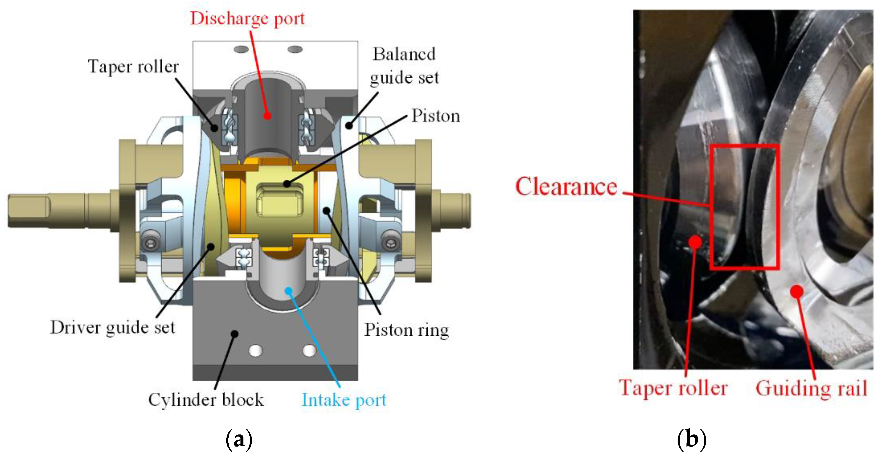
Figure 1.
2D piston pump with a balanced force. (a) Structure diagram; (b) clearance between the guiding rail and the taper rollers.
In the experiment, it was found that the 2D piston pump with a balanced force generated strong vibration when it rotated at high speed, which affected its efficiency. This was mainly caused by the clearance between the guide rail group and the taper roll caused by machining and assembly errors [22], as shown in Figure 1b.
In order to eliminate the assembly clearance between the guide rail and the taper roller, and to reduce the problem of vibration and small flow, the author proposes a taper roller overlap type 2D piston pump [23]. Figure 2 shows the structure of the 2D piston pump with a stacked taper roller set.
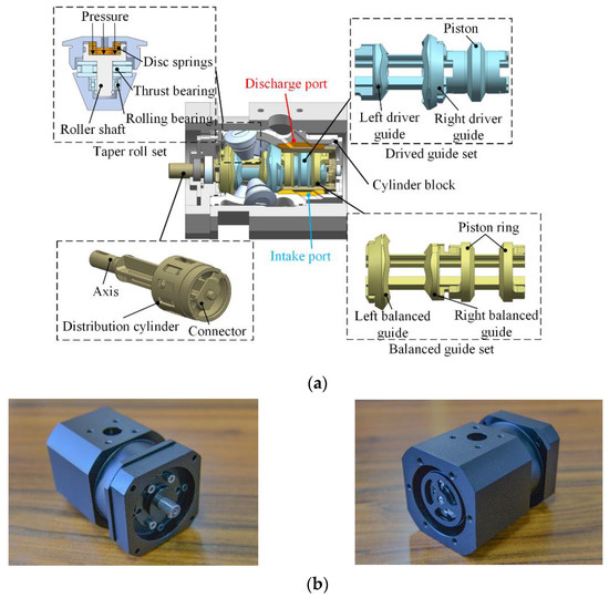
Figure 2.
2D piston pump with a stacked taper roller set. (a) Structure diagram; (b) picture.
The structure of the 2D piston pump with a stacked taper roller set, from left to right, consists of a driver guide set, a taper roller group, a balanced guide set and a distribution cylinder. The driver guide set includes a left driver guide, a right driver guide and a piston. The balanced guide set includes a left balanced guide, a right balanced guide and a piston ring. The guide surfaces are made into a constant acceleration and constant deceleration. When the two guide sets rotate, due to the constraints of the roller-guide mechanism, the two guide sets perform equal acceleration and deceleration in the axial direction. There are ten distribution grooves on the distribution cylinder, and five oil intake windows and five oil discharge windows are staggered on the cylinder block. During the flow distribution process, the distribution groove communicates alternately with the 10 oil-intake and discharge ports on the casing to achieve continuous oil intake and discharge.
When the top of the taper roller is pressurized by oil, the taper roller set closely adheres to the surfaces of the guide rail, eliminating the clearance between them that may be caused by machining or assembly errors, and ensuring that the strokes of the two guide sets always meet the working requirements. The phases of the two guide rail groups are staggered by 36°. When the two guide rail groups move toward the middle position, the distribution grooves communicates with the oil intake and discharge ports, the low-pressure chamber sucks oil and the high-pressure chamber discharges oil, in order to realize the flow-distribution function.
Through the test, it was found that the left and right taper rollers were in close contact with the guide rails relying on the oil pressure, and both left and right guide rails were stressed. There was a large deviation between the unilateral force model of the guide rail and the actual results, so it was necessary to further optimize the mechanical model of the 2D piston pump with a stacked taper roller set. In this paper, the mechanical efficiency model was re-modeled and compared with the unilateral force model of the guide rail. The model took into account the churning loss of the two guides in the oil [24] and the oil resistance during axial movement. Finally, the theoretical calculation and analysis results are compared with the experimental results herein, and the reasons for the differences in the results are explained.
2. Mathematical Model
2.1. Spatial Angle Relationship
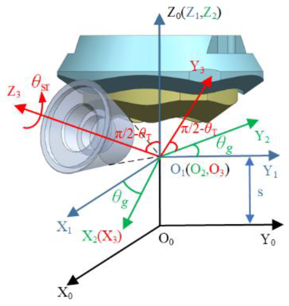
The spatial angle formed by the contact force between the taper roller and the guide rail and the axial and circumferential directions of the 2D pump is very important for the calculation of the mechanical equation, so it is necessary to firstly establish the spatial angle relationship of the roller-guide-rail mechanism [25]. Since the taper roller is affected by the guide rail in the actual working process, its posture will change slightly. In order to establish the space angle transformation more conveniently, it is assumed that the taper roller and the guide rail group always rotate around a central axis of rotation without changing. After coordinate homogeneous transformation, the motion coordinate system O3-X3Y3Z3 is transformed to the global coordinate system O0-X0Y0Z0. The coordinate system is shown in Figure 3.

Figure 3.
Coordinates system.
In the motion coordinate system O3-X3Y3Z3, point O3 coincides with the vertex of the taper roller and falls on the Z0 axis, the Z0 axis is collinear with the rotation axis of the guide rail, and the Z3 axis is collinear with the rotation axis of the taper roller. The coordinates O1-X1Y1Z1 are obtained by translating s along the Z0 axis from the coordinates O0-X0Y0Z0, the coordinates O2-X2Y2Z2 are obtained by rotating the coordinates O1-X1Y1Z1 around the Z1 axis by θg degrees, and the coordinates O3-X3Y3Z3 are obtained by rotating the coordinates O2-X2Y2Z2 around the X2 axis by π/2-θT degrees.
According to the above coordinate homogeneous transformation, the expression of the surface of the taper roller in the O0-X0Y0Z0 is as follows:
where θg is the rotation angle of the guide rail, θsr and θT are the rotation angle and inclination angle of the taper roller, h is the design stroke of two guide sets, L is the distance from the surface of the taper roller to the X3O3Y3 plane, and s is the axial displacement of two guide set.
Since the guide-rail surface is composed of 5 cycles of equal acceleration and deceleration curved surface circular array, only one cycle of the surface needs to be analyzed. The motion law of the axial displacement s of the guide rail can be expressed by Equation (2)
Equation (3) represents the relationship between the surface of the taper roller and the guide rail. Equation (1) can be expressed as a function f(θsr,θg,L) according to the envelope theory of the single parameter surface family. When f(θsr,θg,L) satisfies the constraint equation of Equation (3), the variable θsr can be eliminated to obtain the parametric guide rail surface, namely f(θg,L).
f1(θsr,θg,L) = ∂f(θsr,θg,L)/∂θsr and f2(θsr,θg,L) = ∂f(θsr,θg,L)/∂L is the tangent vector at the contact point of the taper roller. nn = (f1 × f2)/∣f1·f2∣ is the normal vector at the contact point of the taper roller, which is used to indicate the direction of the positive pressure. The vector nn′ is the projection of the normal vector on the bottom surface.
Suppose the circumferential unit vector of the guide rail at the contact point is ec, the Y3 axial unit vector is transformed into the unit vector in the global coordinate system as j3, and the Z0 axial unit vector is k0. Using the above-mentioned angle solution method and combining the constraint condition Equation (3), the following relationship between the spatial angle and the guide rail rotation angle θg and the distance L can be obtained.
The angle between the positive pressure on the inner guide rail and the movement direction, namely the pressure angle αn, and the angle αne between the positive pressure on the inner guide rail and the circumferential vector at the contact point are, respectively.
The angle αf between the friction force on the inner guide rail and the movement direction, and the angle αfe between the friction force on the inner guide rail and the circumferential vector at the contact point are, respectively.
The angle θN between the component of positive pressure of the driver guide set and the Y3 axial vector is.
2.2. Mechanical Efficiency
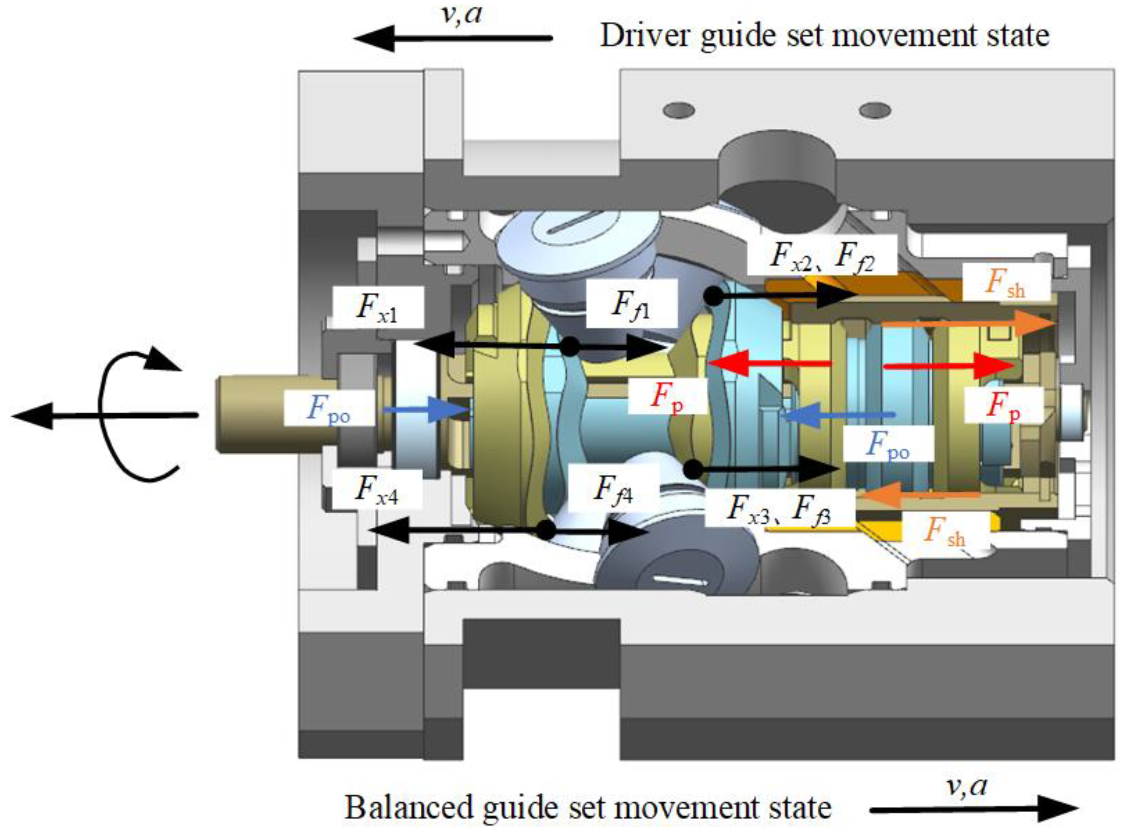
The driver rail group on the far right and the balanced rail group on the far left should be set to their initial positions. In the rotation process from 0° to 18°, the left driver rail and piston accelerate to the left, and the right balanced rail and piston ring accelerate to the right. Figure 4 shows the force of the 2D pump.

Figure 4.
Schematic diagram of the force of two guide sets from 0° to 18°.
The mechanical balance equations of the two guide rail groups are as follows:
where m and a are the mass and acceleration of the guide set, Fx1, Ff1, Fx4 and Ff4 are the axial support and friction forces of the left taper roller to the left two guide rail, Fx2, Ff2, Fx3 and Ff3 are the axial support and friction force of the right taper roller to the right two guide rail, Fp is the hydraulic force on the piston and piston ring, Fpo is the oil resistance on the axial motion of the guide rail, and Fsh is the oil shear force on the piston and piston ring, which is expressed by the following equation:
where Fs1 and Fs4 are the positive pressures of the left taper roller on the left driver guide and the left balanced guide, Fs2 and Fs3 are the positive pressures of the right taper roller on the right driver guide and the right balanced guide, μf is the friction coefficient between the guide rail and the taper roller, μ is the oil dynamic viscosity, p is the load pressure, D1 and L1 are the diameter and the width of the piston and the piston ring, δ is the clearance between the piston, the piston ring and the distribution cylinder, v is the axial movement speed of the two guide sets, ρ is the oil density, S1 and S2 are the oil-blocking area during axial movement of the driver guide rails on both sides, R1 and R2 are the radius of the driver guide rails on both sides, d is the diameter of the piston rod, lg is the length of the guide rail, and n is the rotation speed of the two guide sets. δ1 represents the distances from the edge of the driver guide to the balanced guide. δ2 represents the distances from the edge of the driver guide to the cylinder block. αn′ and αf′ represent the pressure angle of the left and right outer guide rails and the angle between the friction force and the movement direction. Their radius is different from the inner guide rail, so it is different from αn and αf.
Equation (23) expresses the axial movement speed v of the two guide rail sets.
As shown in Figure 5, FN1 and FN2 are the oil pressure on the top of the left and right taper rollers, Fa and Fb are the forces between the taper rollers, and Fa = Fb. The force balance equations of the left and right taper rollers on the y-axis and z-axis was established as shown in the following equation:
where b is the angle of the projection of the contact line onto the bottom surface of the tapered roller, β is the half taper angle, D2 and D3 are the effective pressing surface diameters of the left and right taper rollers, and θN′ is the angle between the component of positive pressure of the balanced guide set and the Y3 axial unit vector. Because of the π/2 phase difference between the two guides group, it is different from θN.
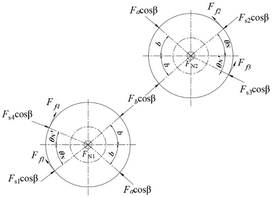
Figure 5.
The force diagram of the taper rollers on the left and right sides.
Combining Equations (9), (10) and (24)–(27), the expressions of Fs1, Fs2, Fs3, and Fs4 can be obtained.
In the course of 18° to 36°, the two guide sets keep the original direction of movement and perform the deceleration movement. Because the bilateral force model does not have problems related to the direction of the pressure, the rotation speed and the load in the unilateral force model, the force of the two guide rails is similar to that of the equal acceleration phase, as shown in Figure 6.
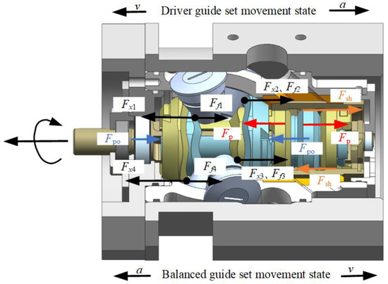
Figure 6.
Schematic diagram of the force of two guide sets from 18° to 36°.
The mechanical balance equations of the two guide sets are shown in Equations (28) and (29).
The force of the taper roller remains unchanged. Therefore, the torque Ti received by the two guide sets during the rotation from 0° to 36° is as shown in Equation (30).
The 2D piston pump is subject to the oil churning loss torque Tc of the guide rails in the oil and the oil shear torque Ts in the clearance between the cylinder block and distribution cylinder when functioning. Tc fits the curve formula through simulation and experiment [21], which is expressed as Equations (31) and (32).
where D4 is the outer diameter of the distribution cylinder, L2 and δ3 is the contact width and the clearance between the distribution cylinder and the cylinder block.
Combining the above calculations, Equation (33) expresses the torque T required by the 2D pump when the two guide sets turn from 0° to 36°.
The mechanical efficiency ηm can be calculated by Equation (34):
where VD is the 2D pump displacement, and is the average value of the torque received by the two guide sets.
3. Simulation Results
According to the mathematical models listed above, the influence of rotation speed and load on torque were analyzed and compared. The relevant setting parameters are shown in Table 1.

Table 1.
Simulation parameter.
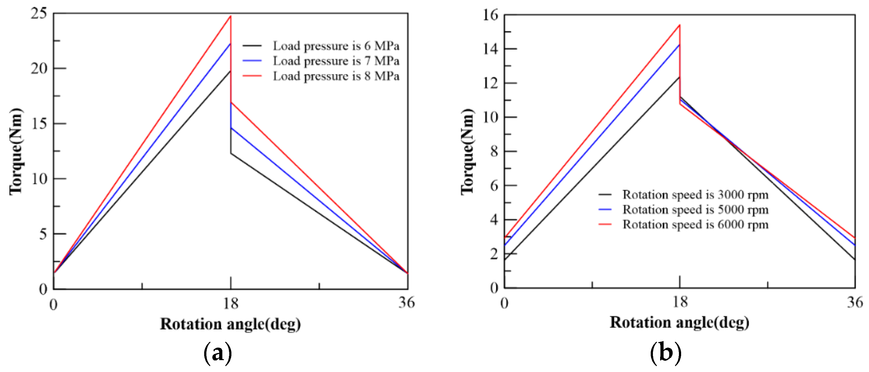
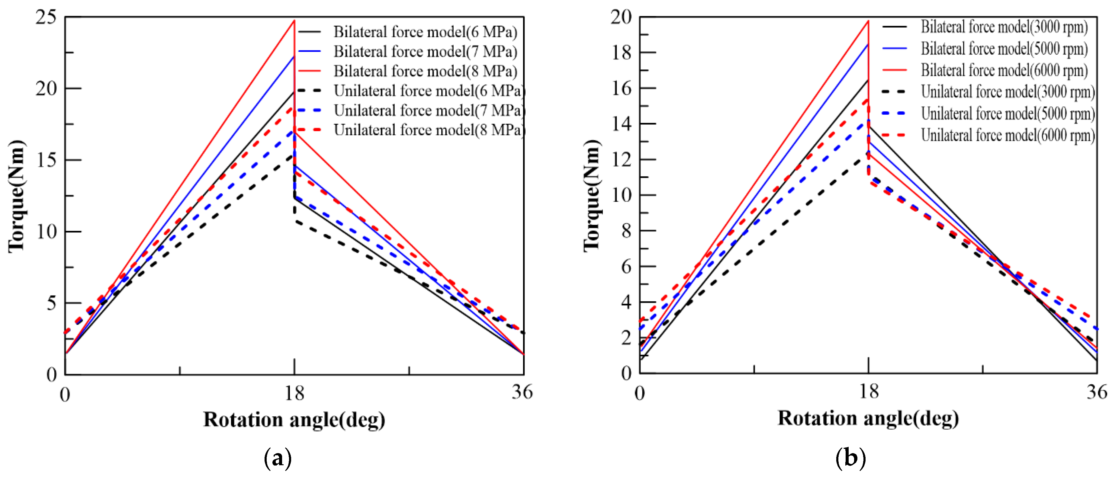
The variation of torque with rotation angle is shown in Figure 7. It can be seen from the curve in the figure that the peak torque increases with the increase in the rotational speed and load. When the guide rail set is rotated to 18°, the torque will suddenly change. The reason for the sudden change in torque is that the acceleration direction switches when the guide sets move to the middle position, and the support force of the taper roller to the guide rail on both sides of the two guide sets changes suddenly. It can be seen from Figure 7a that the torque increases with the increase in the load pressure, mainly due to the increased oil pressure on the piston and the piston ring. Figure 7b shows that the torque increases with the rotation speed, which is mainly due to the increase in the axial acceleration of the transmission part and the increase in the oil shear force.
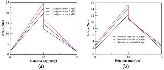
Figure 7.
Torque curve. (a) The speed is 6000 rpm; (b) The load pressure is 6 MPa.
The calculation results of the bilateral force model of the guide rail with the unilateral force model of the guide rail were compared, as shown in Figure 8. It can be seen from the figure that the average and peak values of the torque of the bilateral force model of the guide rail are larger than the unilateral force model. The specific reason is that the two guide sets of the bilateral force model have a supporting force opposite to the rotation speed, so the required rotation torque is increased. When the 0° and 36° guide rails are at the highest and lowest points of the stroke, the torque of the bilateral force model is smaller than that of the unilateral force model. This is because the calculation angle in the bilateral force model of the guide rail uses a space angle to calculate, which is more accurate than the angle conversion of the unilateral force model.
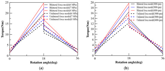
Figure 8.
Comparison of the calculation results of the bilateral and unilateral force model of the guide rail. (a) The speed is 6000 rpm; (b) Load pressure is 6 MPa.
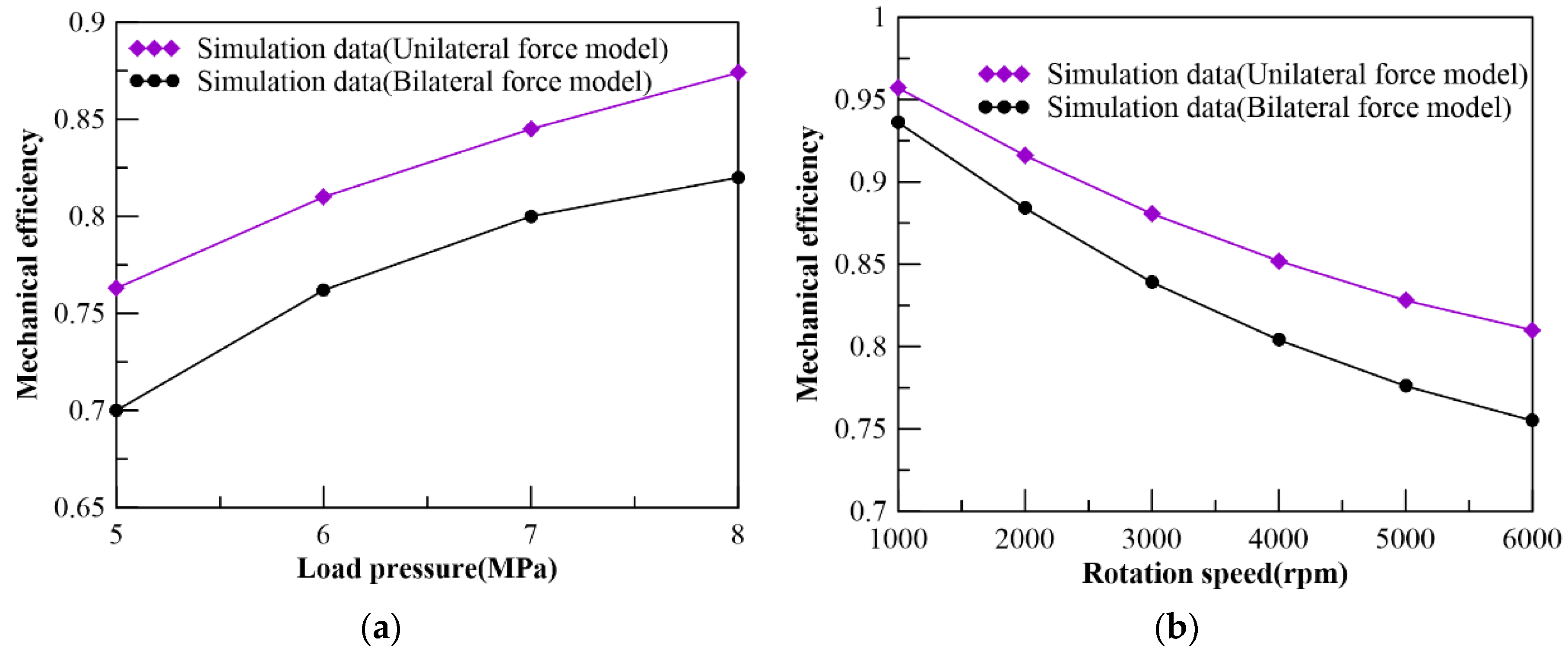
Figure 9 shows the mechanical efficiency under different operating conditions. The torque rise speed is less than the load pressure rise speed during the load pressure increases, so that the mechanical efficiency increases. The rotational torque increases during the load pressure increases, thereby reducing the mechanical efficiency. It can be seen from the mechanical efficiency curves of the two models that the torque calculated by the bilateral force model of the guide rail is greater than that of the unilateral force model, and the final mechanical efficiency is significantly lower than that of the unilateral force model.
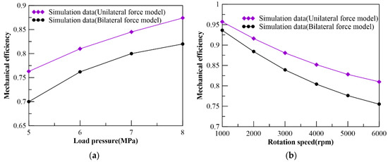
Figure 9.
Mechanical efficiency change curve. (a) The speed is 6000 rpm; (b) Load pressure is 6 MPa.
4. Experimental Research
A test rig was built to conduct experimental research on the prototype. The main parameters of the prototype are shown in Table 2:
Table 2.
2D pump prototype parameters.
Figure 10 is the principal diagram of the test rig, which includes a supply pump station, a spindle three-phase motor, a torque sensor, a pressure sensor, a flowmeter, and an adjustable pressure valve. The adjustable pressure valve simulates the load pressure, and the torque and the pressure sensor measured data are collected by the NI data acquisition card and display on the compute. The flowmeter is displayed by the matching digital display meter. The flowmeter used in the experiment has a range of 0.05–80 L/min and an accuracy of 0.3%; the torque range of the torque sensor is 0–20 Nm, the speed range is 0–18,000 rpm, and the accuracy is ± 0.1%; the range of the pressure sensor is 0 to 10 MPa with 0.3% accuracy.
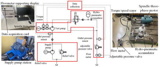
Figure 10.
Schematic diagram of test rig.
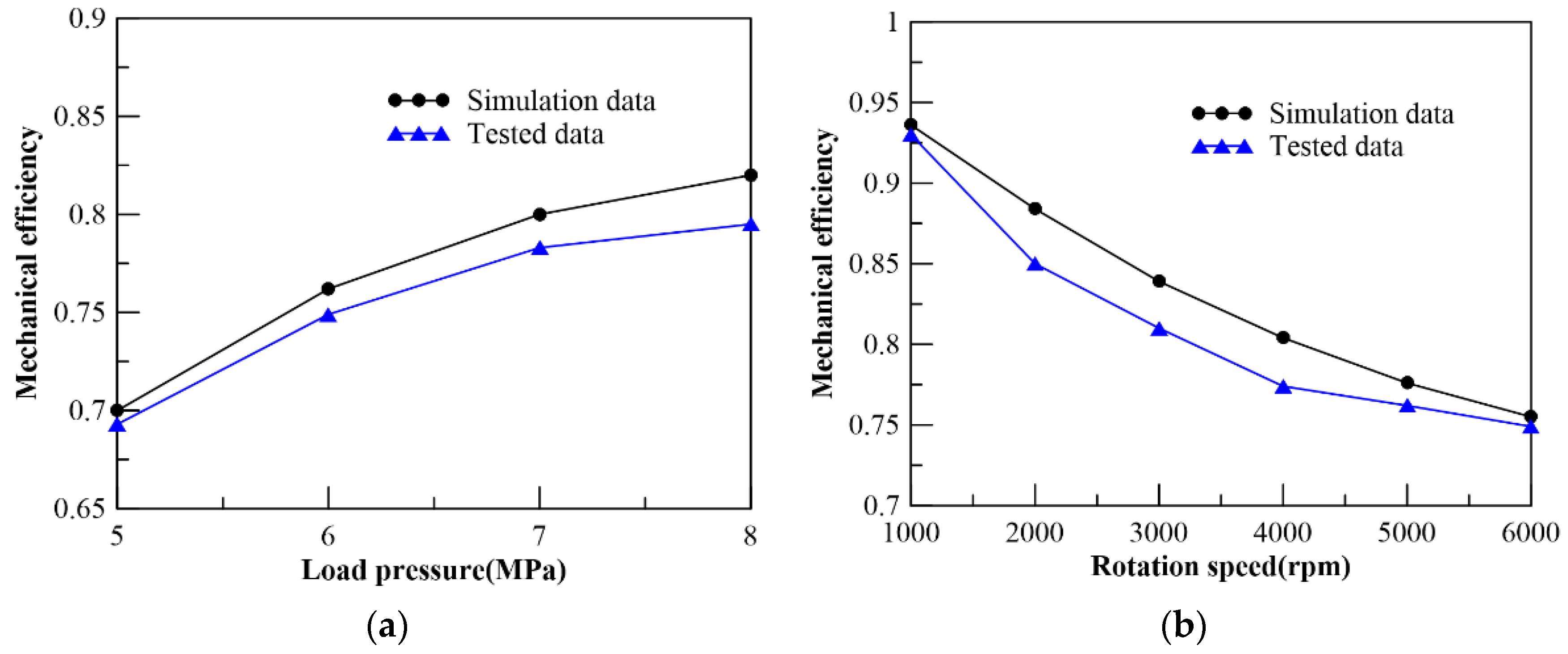
Before the test, adjust the relief valve to an appropriate pressure to ensure that the oil circuit system can quickly build up pressure when the 2D piston pump is started, so that the taper roller set can be compressed, and then adjust the motor frequency converter to change the motor speed, and then read it from the computer Torque data. Take 1000 rpm as a step and increase the speed. The experimental mechanical efficiency curve under different working conditions is shown in Figure 11.
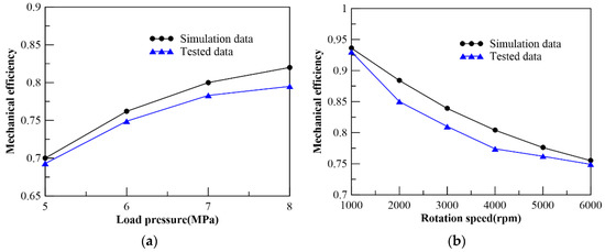
Figure 11.
Test results of mechanical efficiency. (a) Speed is 6000 rpm; (b) Load pressure is 6 MPa.
It can be seen from Figure 11 that the mechanical efficiency calculation result of the bilateral force model is lower than that of the unilateral force model and is closer to the test curve. When the speed and load pressure are both low, the experimental mechanical efficiency is basically consistent with the simulation results. However, the difference between the experiment and simulation results gradually increases as the load increases gradually. This difference also appears when comparing the unilateral force model with the experimental results. The possible reason is that the stacked taper roller sets are pressed against each other by oil pressure. When the load gradually increase, the supporting force between the two taper rollers and between the taper rollers and the guide rail also begins to increase, resulting in an increase in the rolling friction coefficient [26], so affecting the mechanical efficiency.
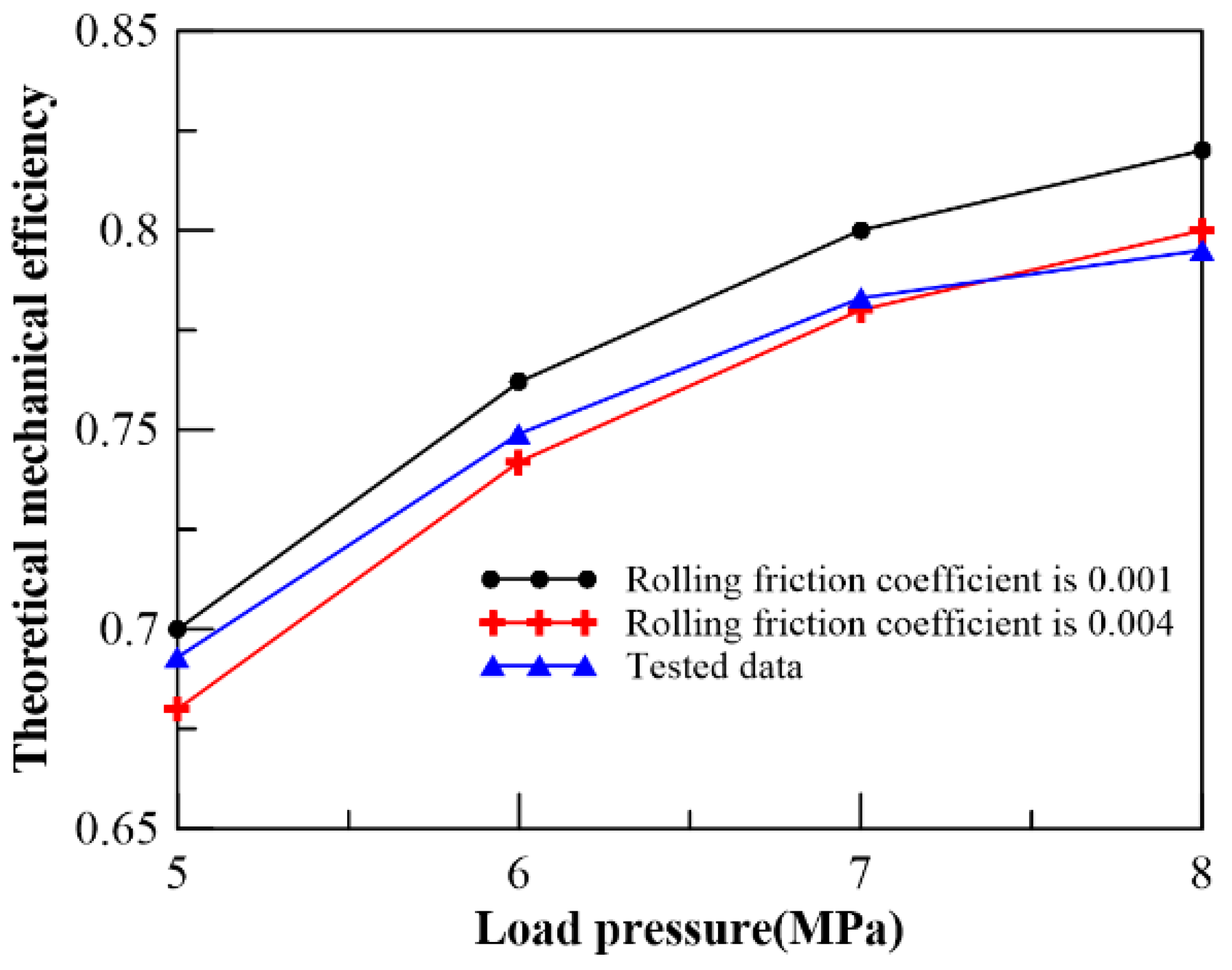
Figure 12 is a graph of mechanical efficiency and rolling friction coefficient at 6000 rpm. When the load pressure is 5 MPa and 8 MPa, the rolling friction coefficient is about 0.001 and 0.004, respectively. In the actual working conditions of the roller–guide-rail mechanism, the linear contact may become point contact and the coexistence of rolling and sliding friction due to the deflection of the taper roller. Therefore, the determination of the relationship between the actual rolling friction coefficient and the load pressure needs to be further studied.

Figure 12.
Curve graph of mechanical efficiency and rolling friction coefficient at 6000 rpm.
5. Conclusions
Based on the reassessment of the transmission part of the stacked taper roller set, this paper optimizes the mechanical efficiency mathematical model, and compares it with the unilateral force model of the guide rail. Finally, the experimental results were compared with the simulation results of the bilateral force model, and the differences in the results were explained. The conclusions can be summarized as follows:
- (1)
- The mechanical efficiency of the bilateral force model of the 2D piston pump with a stacked taper roller set is lower than that of the unilateral force model. The specific reason is that the guide sets are subjected to the opposite support force to the direction of rotation when rotating, which causes the torque of the bilateral force model of the guide rail to be greater than that of the unilateral force model. Therefore, the mechanical efficiency model established based on the bilateral force of the guide rail is closer to the test results than the unilateral force model.
- (2)
- In the case of the 2D piston pump with a stacked taper roller set at high speed, the transmission loss of the roller–guide-rail mechanism and the oil shear loss are large, so the mechanical efficiency gradually decreases as the speed increases. When the load gradually increases, since the speed of the increasing torque is less than the speed of increasing load pressure, so the mechanical efficiency increases with the increase in the load pressure. When the load pressure is high, the test results of the mechanical efficiency are quite different from the numerical simulation results. The possible reasons are that the higher oil pressure increases the supporting force between two taper rollers and between the taper rollers and the guide rail, which increases the size of the contact area, resulting in an increase in the rolling friction coefficient, which affects the mechanical efficiency.
In the future, the bilateral force model of guide rails with variable pressing forces on both sides of the taper rollers established in this paper can provide a theoretical basis for the design of the 2D piston pump under different pressing forces, with further analysis of the influence of the different sizes of the pressing force of the taper rollers on both sides of its mechanical efficiency.
Author Contributions
Methodology, H.W.; conceptualization, J.R.; formal analysis, H.W.; investigation, H.W.; resources, J.R.; software, H.W. and C.R.; validation, C.T.; data curation, H.W.; writing—original draft preparation, H.W.; writing—review and editing, J.R. and C.D.; supervision, S.L.; project administration, J.R.; funding acquisition, S.L. and J.R. All authors have read and agreed to the published version of the manuscript.
Funding
This research work was supported by the National Key Research and Development Program (Grant No. 2019YFB2005202) and Zhejiang Provincial Natural Science Foundation (Grant No. LY21E050013).
Institutional Review Board Statement
Not applicable.
Informed Consent Statement
Not applicable.
Data Availability Statement
Not applicable.
Conflicts of Interest
The authors declare no conflict of interest.
Nomenclature
| 2D | Two-dimensional |
| ec | The circumferential unit vector of the guide rail at the contact point |
| j3 | The Y3 axial unit vector is transformed into the unit vector in the global coordinate system |
| k0 | The Z0 axial unit vector |
| nn | The normal vector at the contact point of the taper roller |
| nn’ | The projection of the normal vector on the bottom surface |
| θg | The rotation angle of the guide rail |
| θsr | The rotation angle of the taper roller |
| θT | The inclination angle of the taper roller |
| h | The design stroke of two guide sets |
| L | The distance from the outer surface of the taper roller to the plane |
| s | The axial displacement of two guide set |
| αn | The positive pressure on the inner guide rail and the movement direction |
| αne | The angle between the positive pressure on the inner guide rail and the circumferential unit vector at the contact point |
| αf | The angle between the friction force on the inner guide rail and the movement direction |
| αfe | The angle between the friction force on the inner guide rail and the circumferential unit vector at the contact point |
| αn′ | The pressure angle of the left and right outer guide rails |
| αf′ | The angle between the friction force and the movement direction |
| θN | The angle between the positive pressure component of the driver guide set and the Y3 axial unit vector |
| θN′ | The angle between the positive pressure component of the balanced guide set and the Y3 axial unit vector |
| m | The mass of the two guide sets |
| a | The acceleration of the two guide sets |
| Fx1 | The axial support of the left taper roller to the left driver guide |
| Ff1 | The axial friction forces of the left taper roller to the left driver guide |
| Fx4 | The axial support of the left taper roller to the left balanced guide |
| Ff4 | The axial friction forces of the left taper roller to the left balanced guide |
| Fx2 | The axial support of the right taper roller to the right driver guide |
| Ff2 | The axial friction force of the right taper roller to the right driver guide |
| Fx3 | The axial support of the right taper roller to the right balanced guide |
| Ff3 | The axial friction force of the right taper roller to the right balanced guide |
| Fp | The oil pressure of the high pressure chamber oil on the piston and the piston ring |
| Fsh | The oil shear force between the piston and the distribution cylinder |
| Fpo | The oil resistance on the axial movement of the guide rail |
| Fs1 | The positive pressures of the left taper roller set on the left driver guide |
| Fs4 | The positive pressures of the left taper roller set on the left balanced guide |
| Fs2 | The positive pressures of the right taper roller set on the right driver guide |
| Fs3 | The positive pressures of the right taper roller set on the right balanced guide |
| μf | The friction coefficient between the guide rail and the taper roller |
| μ | The dynamic viscosity of the oil |
| D1 | The diameter of the piston and the piston ring |
| d | The diameter of the piston rod |
| L1 | The width of the piston and the piston ring |
| δ | The clearance between the piston, the piston ring and the distribution cylinder |
| v | The axial movement speed of the two guide sets |
| ρ | The oil density |
| p | The load pressure |
| S1 | The oil blocking area during axial movement of the left driver guide rails |
| S2 | The oil blocking area during axial movement of the right driver guide rails |
| R1 | The radius of the left driver guide rails |
| R2 | The radius of the right driver guide rails |
| lg | The length of the guide rail |
| n | The rotation speed |
| δ1 | The distances from the edge of the left driver guide to the left balanced guide |
| δ2 | The distances from the right driver guide to the cylinder block |
| FN1 | The oil pressure on the top of the left taper rollers |
| FN2 | The oil pressure on the top of the right taper rollers |
| Fa, Fb | The forces between the taper rollers |
| β | The half taper angle of the taper roller |
| b | The angle of the projection of the contact line onto the bottom surface of the tapered roller |
| D2 | The effective pressing surface diameters of the left taper rollers |
| D3 | The effective pressing surface diameters of the right taper rollers |
| Ti | The torque received by the driver guide set and the balanced guide set |
| Tc | The oil churning loss torque |
| Ts | The oil shear torque |
| D4 | The outer diameter of the distribution cylinder |
| L2 | The contact width between the distribution cylinder and the cylinder block |
| δ3 | The clearance between the distribution cylinder and the cylinder block |
| T | Torque input by the motor |
| ηm | The mechanical efficiency |
| VD | The 2D pump displacement |
| The average value of the torque received by the two guide sets |
References
- Bensaad, D.; Soualhi, A.; Guillet, F. A new leaky piston identification method in an axial piston pump based on the extended Kalman filter. Measurement 2019, 148, 106921. [Google Scholar] [CrossRef]
- He, W.; Huang, J.H.; Hao, H.M.; Quan, L.; Ji, S.X.; Zhao, B. Design and Analysis of a Swashplate Control System for an Asymmetric Axial Piston Pump. J. Dyn. Syst. Meas. Control-Trans. ASME 2020, 142, 021005. [Google Scholar] [CrossRef]
- Zhao, J.A.; Fu, Y.L.; Ma, J.M.; Fu, J.; Chao, Q.; Wang, Y. Review of cylinder block/valve plate interface in axial piston pumps: Theoretical models, experimental investigations, and optimal design. Chin. J. Aeronaut. 2021, 34, 111–134. [Google Scholar] [CrossRef]
- Xu, B.; Zhang, J.H.; Yang, H.Y. Investigation on structural optimization of anti-overturning slipper of axial piston pump. Sci. China-Technol. Sci. 2012, 55, 3010–3018. [Google Scholar] [CrossRef]
- Jiang, J.H.; Wang, Z.B.; Li, G.Q. The Impact of Slipper Microstructure on Slipper-Swashplate Lubrication Interface in Axial Piston Pump. IEEE Access 2020, 8, 222865–222875. [Google Scholar] [CrossRef]
- Tang, H.S.; Ren, Y.; Xiang, J.W. Power loss characteristics analysis of slipper pair in axial piston pump considering thermoelastohydrodynamic deformation. Lubr. Sci. 2019, 31, 381–403. [Google Scholar] [CrossRef]
- Zhang, J.H.; Lyu, F.; Xu, B.; Huang, W.D.; Wu, W.; Guo, Z.M.; Xu, H.G.; Huang, X.C. Simulation and experimental investigation on low wear rate surface contour of piston/cylinder pair in an axial piston pump. Tribol. Int. 2021, 162, 107127. [Google Scholar] [CrossRef]
- Guan, D.; Jing, L.; Han, X.; Wang, L.H.; Gong, J.J. Theoretical modeling and numerical simulation of dynamic contact characteristics of a spherical pump with variable friction coefficient. Proc. Inst. Mech. Eng. Part J J. Eng. Tribol. 2021, 236, 434–446. [Google Scholar] [CrossRef]
- Meng, X.X.; Ge, C.; Liang, H.X.; Lu, X.Q.; Ma, X. Lubrication characteristics of the slipper-swash-plate interface in a swash-plate-type axial piston pump. Proc. Inst. Mech. Eng. Part C J. Eng. Mech. Eng. Sci. 2021, 235, 639–651. [Google Scholar] [CrossRef]
- Sliwinski, P.; Patrosz, P. Methods of Determining Pressure Drop in Internal Channels of a Hydraulic Motor. Energies 2021, 14, 5669. [Google Scholar] [CrossRef]
- Kollek, W.; Osinski, P.; Stosiak, M.; Wilczynski, A.; Cichon, P. Problems relating to high-pressure gear micropumps. Arch. Civ. Mech. Eng. 2014, 14, 88–95. [Google Scholar] [CrossRef]
- Karpenko, M.; Bogdevičius, M. Review of energy-saving technologies in modern hydraulic drives. Moksl.–Liet. Ateitis/Sci. Future Lith. 2017, 9, 553–558. [Google Scholar] [CrossRef] [Green Version]
- Zheng, F.X.; Li, S.; Ding, C.; Zhao, J.T.; Ruan, J. Theoretical and experimental research on the cartridge two-dimensional (2D) electro-hydraulic servo valve. Adv. Mech. Eng. 2021, 13, 1687814021996532. [Google Scholar] [CrossRef]
- Meng, B.; Xu, H.; Ruan, J.; Li, S. Theoretical and experimental investigation on novel 2D maglev servo proportional valve. Chin. J. Aeronaut. 2021, 34, 416–431. [Google Scholar] [CrossRef]
- Ding, C.; Zhu, Y.H.; Liu, L.; Tong, C.W.; Ruan, J. Research on a Novel Flowmeter With Parallel Two-Dimensional Pistons as Its Metering Units. IEEE Access 2019, 7, 110912–110927. [Google Scholar] [CrossRef]
- Jin, D.C.; Ruan, J.; Li, S.; Meng, B.; Wang, L.F. Modelling and validation of a roller-cam rail mechanism used in a 2D piston pump. J. Zhejiang Univ. Sci. A 2019, 20, 201–217. [Google Scholar] [CrossRef]
- Shentu, S.N.; Ruan, J.; Qian, J.Y.; Meng, B.; Wang, L.F.; Guo, S.S. Study of flow ripple characteristics in an innovative two-dimensional fuel piston pump. J. Braz. Soc. Mech. Sci. Eng. 2019, 41, 1–15. [Google Scholar] [CrossRef]
- Xing, T.; Xu, Y.Z.; Ruan, J. Two-dimensional piston pump: Principle, design, and testing for aviation fuel pumps. Chin. J. Aeronaut. 2020, 33, 1349–1360. [Google Scholar] [CrossRef]
- Huang, Y.; Ruan, J.; Zhang, C.C.; Ding, C.; Li, S. Research on the Mechanical Efficiency of High-Speed 2D Piston Pumps. Processes 2020, 8, 853. [Google Scholar] [CrossRef]
- Huang, Y.; Ruan, J.; Chen, Y.; Ding, C.; Li, S. Research on the Volumetric Efficiency of 2D Piston Pumps with a Balanced Force. Energies 2020, 13, 4796. [Google Scholar] [CrossRef]
- Wang, H.; Li, S.; Ruan, J. Design and research of two-dimensional fuel pump of inertia force balanced. Acta Aeronaut. Astronaut. Sin. 2020, 4, 1–13. (In Chinese) [Google Scholar] [CrossRef]
- Huang, Y.; Ruan, J.; Ding, C.; Li, S. Effect of clearance on volumetric efficiency in 2D piston pumps. Adv. Mech. Eng. 2021, 13, 16878140211047727. [Google Scholar] [CrossRef]
- Wang, H.Y.; Ding, C.; Huang, Y.; Li, S.; Ruan, J. Design and research of 2D piston pumps with a stacked taper roller set. Proc. Inst. Mech. Eng. Part C J. Eng. Mech. Eng. Sci. 2021, 09544062211028271. [Google Scholar] [CrossRef]
- Huang, Y.; Ding, C.; Wang, H.Y.; Ruan, J. Numerical and experimental study on the churning losses of 2D high-speed piston pumps. Eng. Appl. Comput. Fluid Mech. 2020, 14, 764–777. [Google Scholar] [CrossRef]
- Zhu, K.; Ruan, C.T.; Wang, H.Y.; Li, S.; Ruan, J. Analysis of the Torque Loss of High-Speed Transmission Mechanism with a Stacked Roller Set. Machines 2021, 9, 140. [Google Scholar] [CrossRef]
- Zhang, Y.M.; Liu, Y.Z. Research on the rolling contact fatigue life of the bearing considering the friction effect. Proc. Inst. Mech. Eng. Part C J. Eng. Mech. Eng. Sci. 2021, 235, 2238–2264. [Google Scholar] [CrossRef]


Publisher’s Note: MDPI stays neutral with regard to jurisdictional claims in published maps and institutional affiliations. |
© 2022 by the authors. Licensee MDPI, Basel, Switzerland. This article is an open access article distributed under the terms and conditions of the Creative Commons Attribution (CC BY) license (https://creativecommons.org/licenses/by/4.0/).