
RPEOD: A Real-Time Pose Estimation and Object Detection System for Aerial Robot Target Tracking


Abstract
:1. Introduction
- The RPEOD system uses a sparse optical flow algorithm to track the Shi-Tomasi [10] corner, and the feature describing and matching are not required in this process. After CUDA acceleration, the whole state estimator can calculate in real time on the onboard computer carried by the MAV.
- The local bundle adjustment is restricted in a narrow sliding window, which dramatically reduces the number of variables in the back-end optimization process. Meanwhile, the computation complexity of the RPEOD system is bound by the additional marginalization scheme.
- We proposed YZNet, an extremely lightweight neural inference structure, and took it as the backbone in YOLOV5, which can prominently reduce the number of neural network weights and inference delay on the premise of maintaining object detection accuracy so that the deep neural network can run in real time on the low-power onboard computer.
2. Related Work
2.1. Robot Pose Estimation
2.2. Neural Inference Acceleration Technology
3. Aerial Robot Pose Estimator
3.1. Feature Extracting and Tracking
3.2. Inertial Measurements Preintegration
3.3. Tightly Coupled Aerial Robot Pose Estimation
4. Designing Efficient CNNs for Real-Time Object Detection
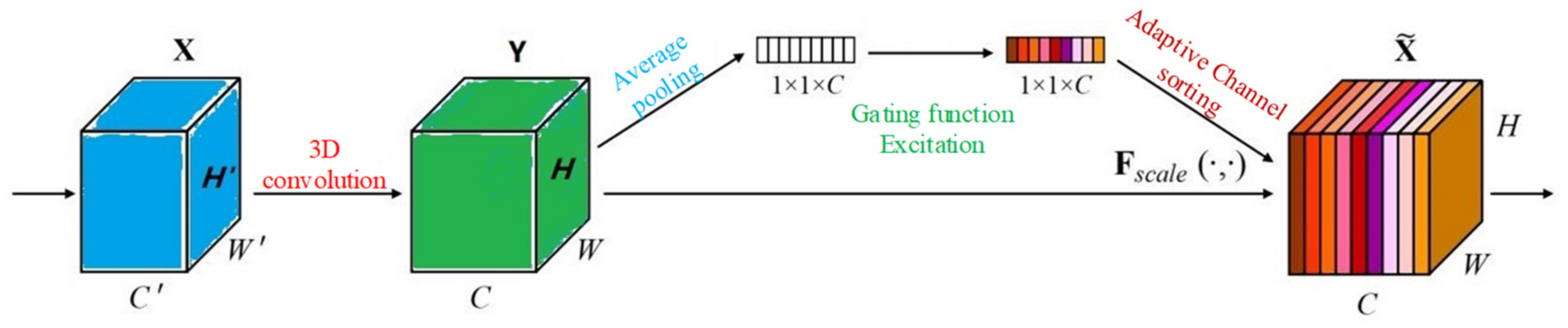
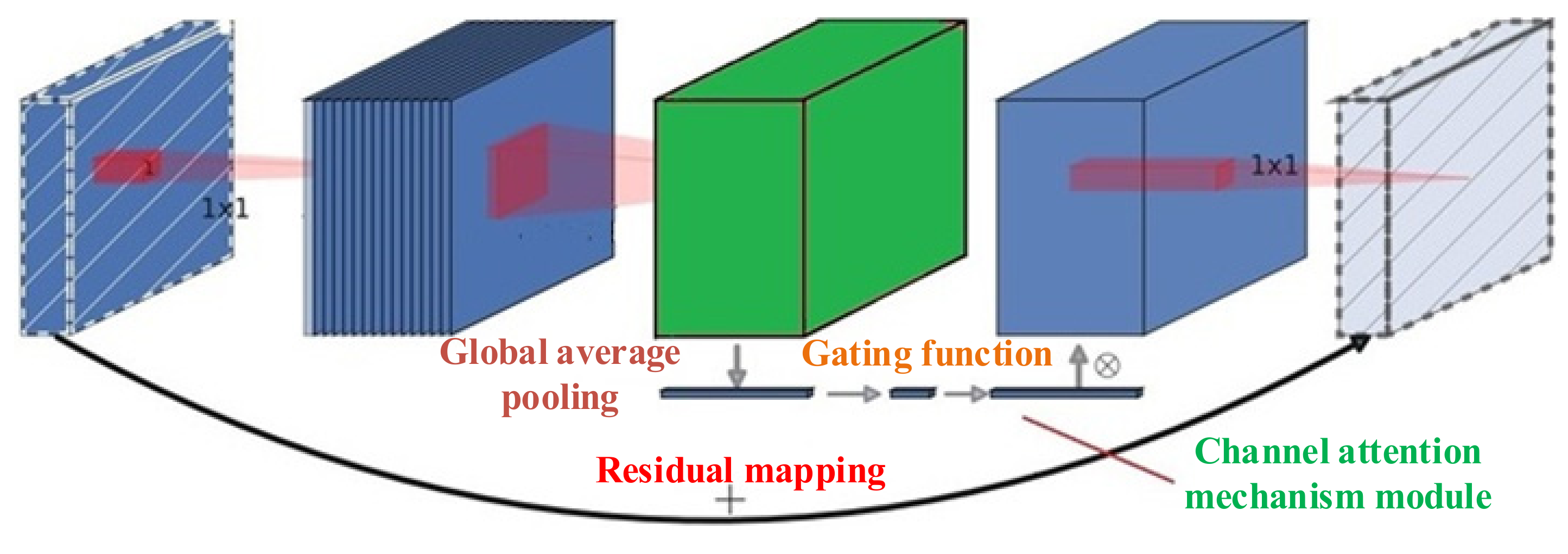
4.1. Channel Attention Module
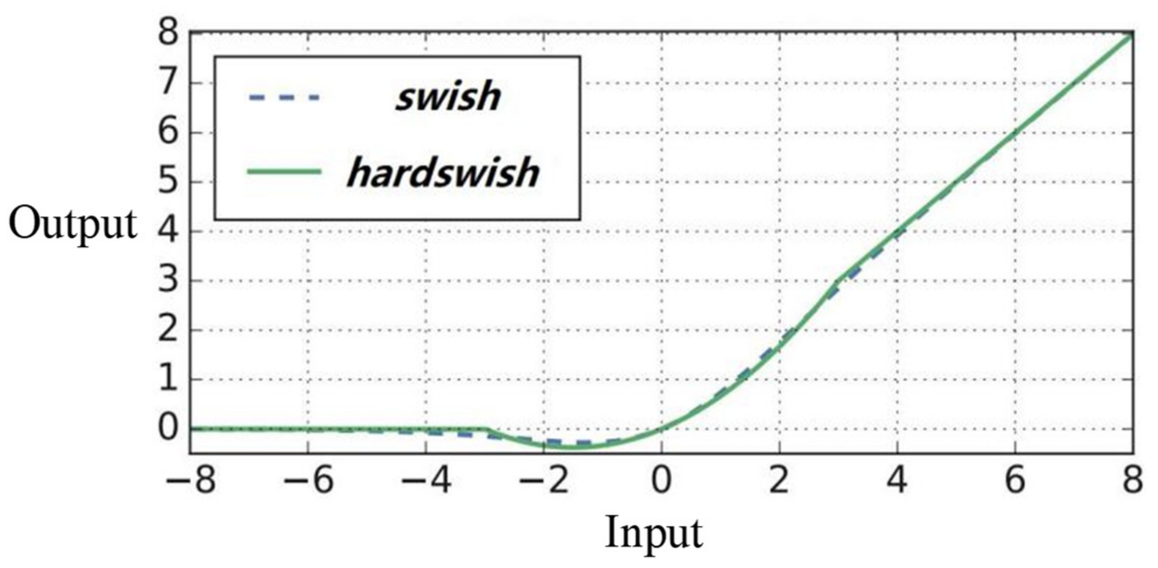
4.2. Nonlinear Activation Function
4.3. Normalization of the Network Activation
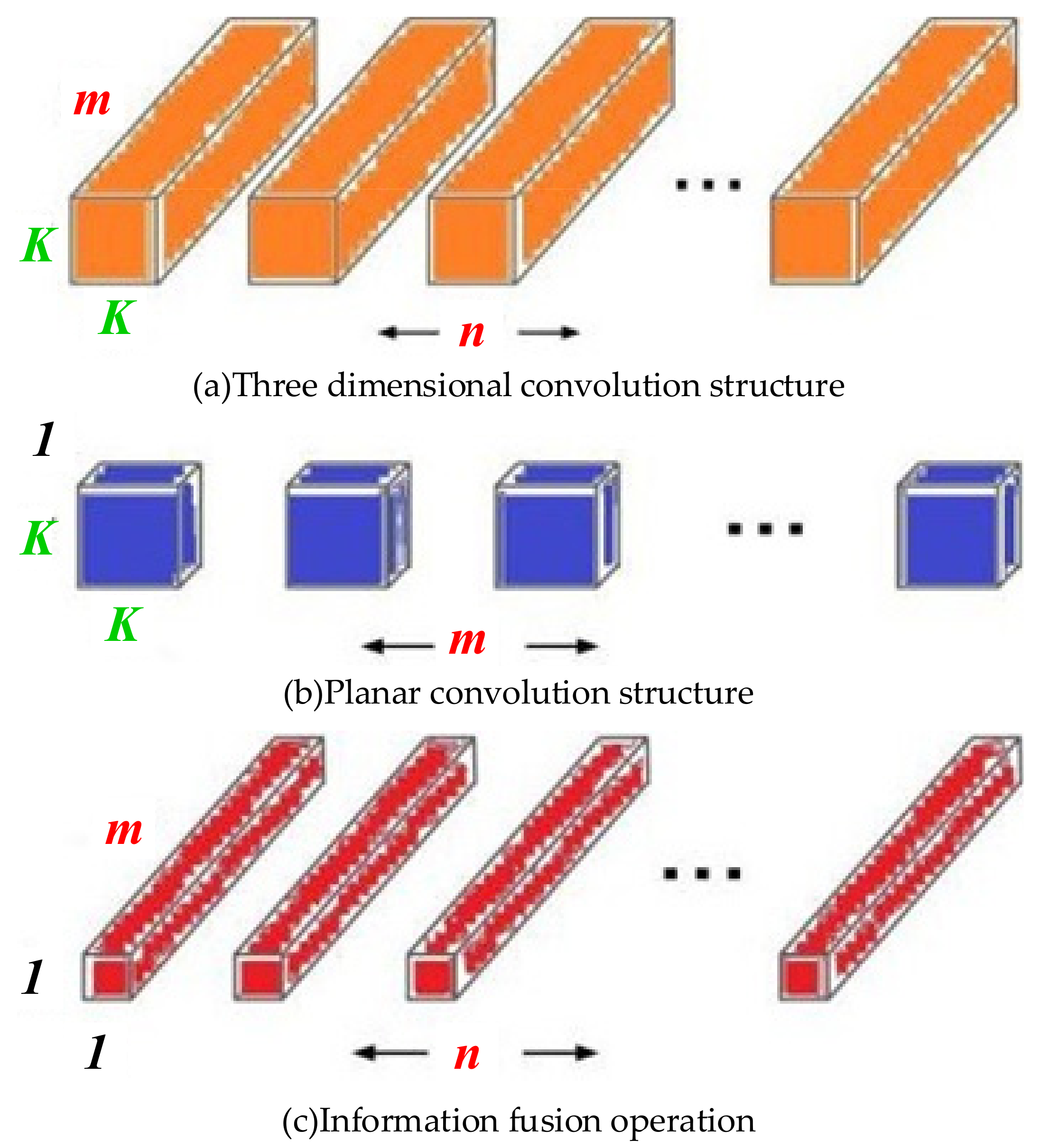
4.4. Efficient Blocks for Inference
4.5. Building Efficient CNNs
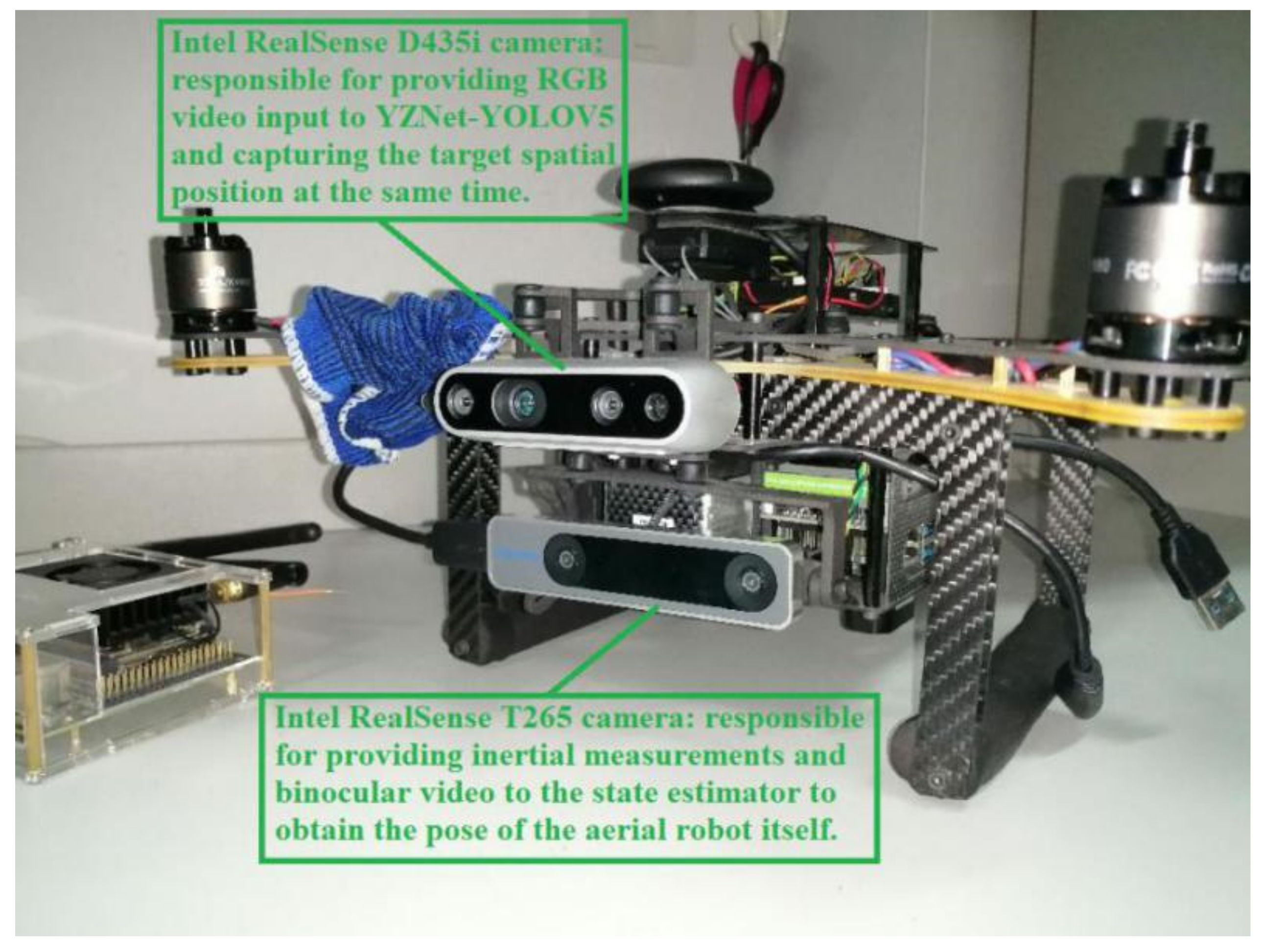
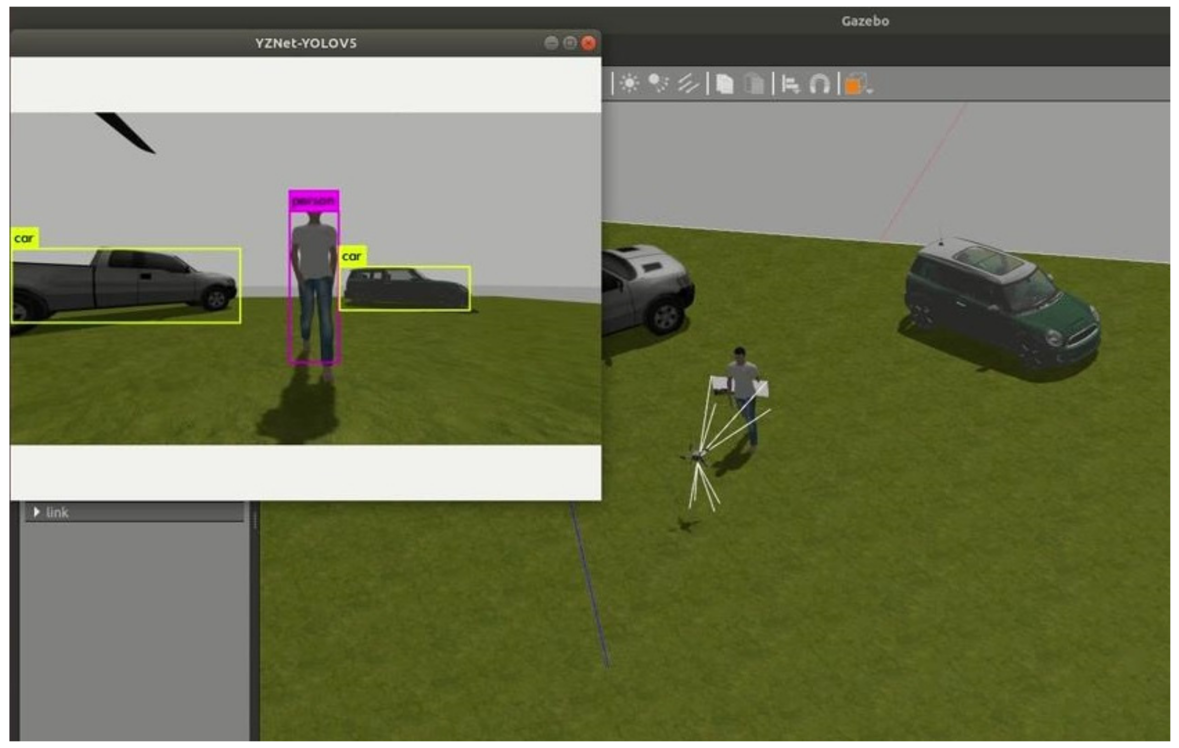
5. Implementation for Target-Tracking System
6. Experiments
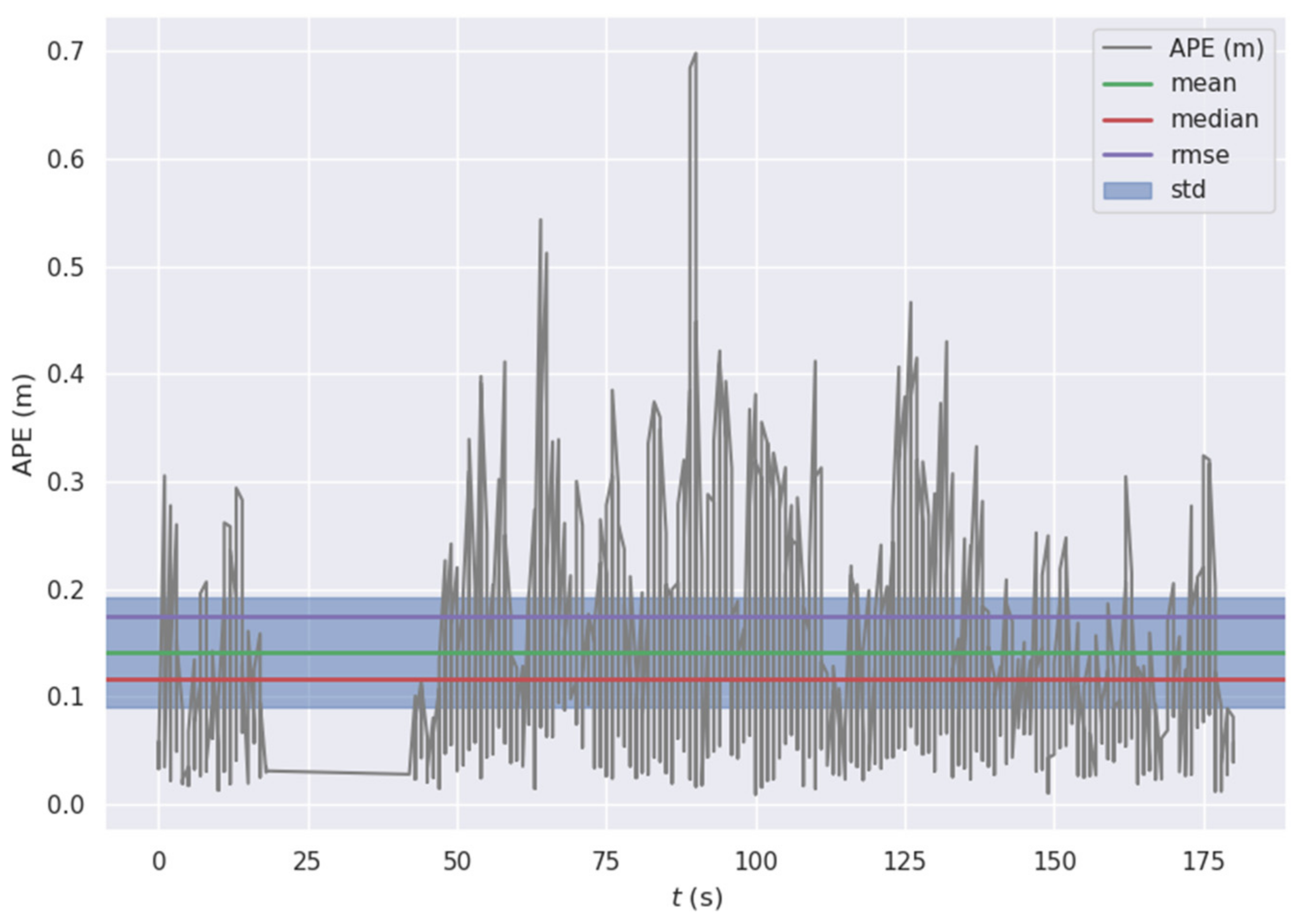
6.1. Pose Estimator
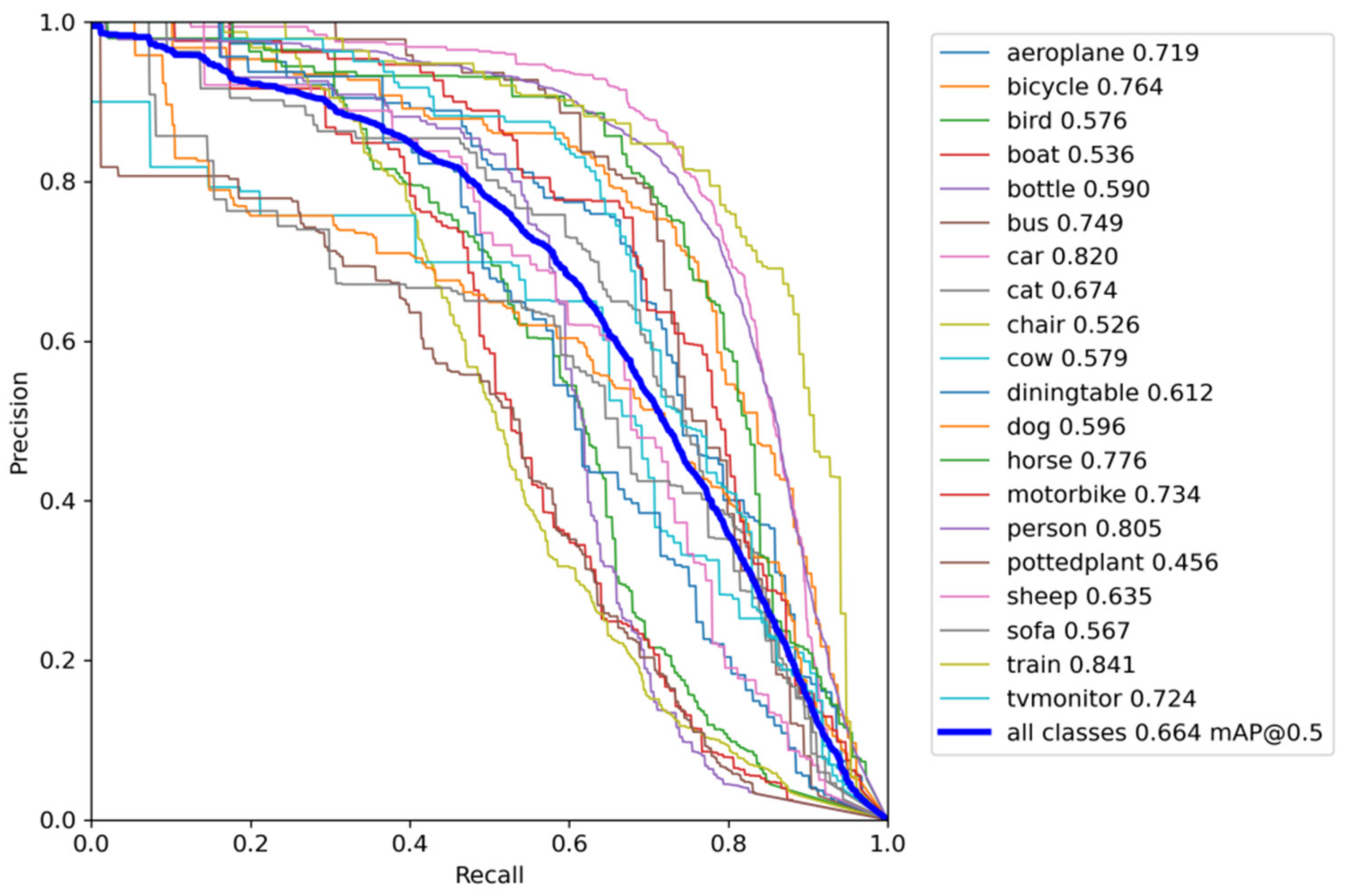
6.2. Object Detector
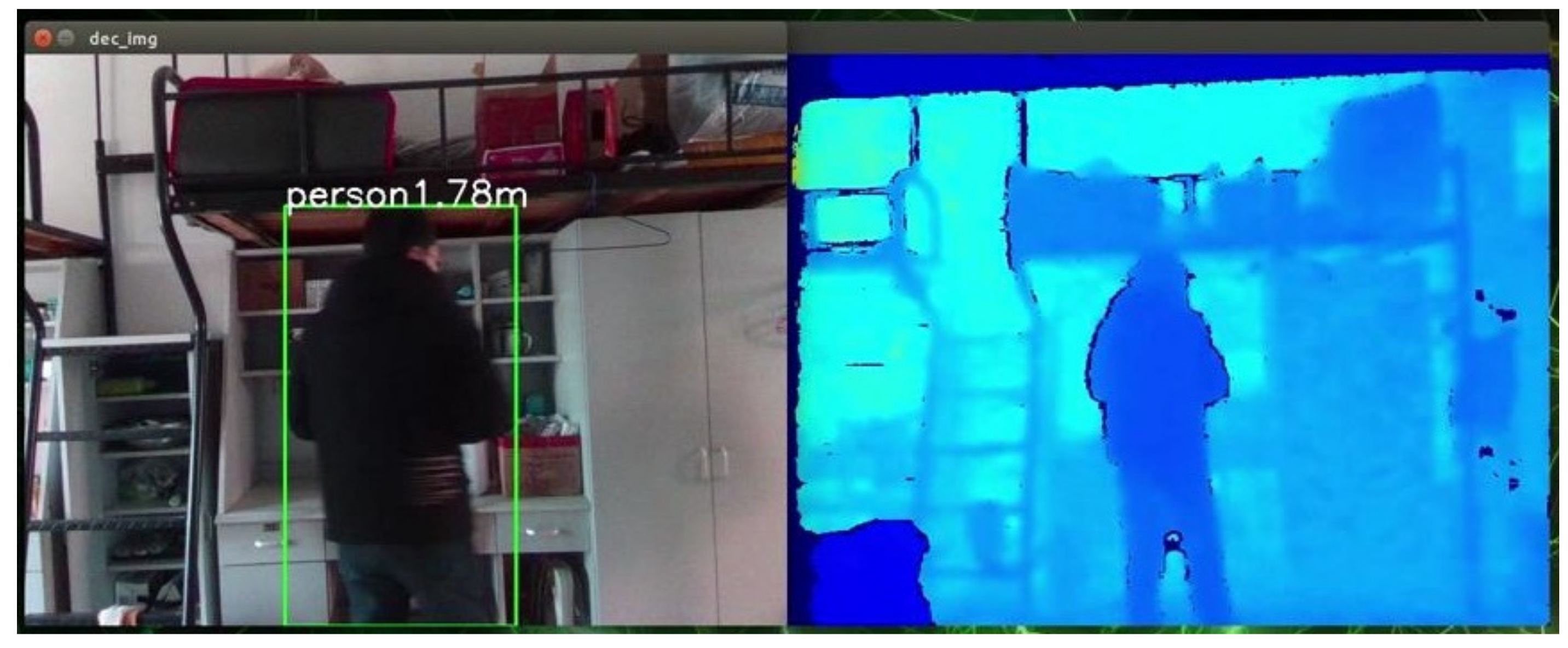
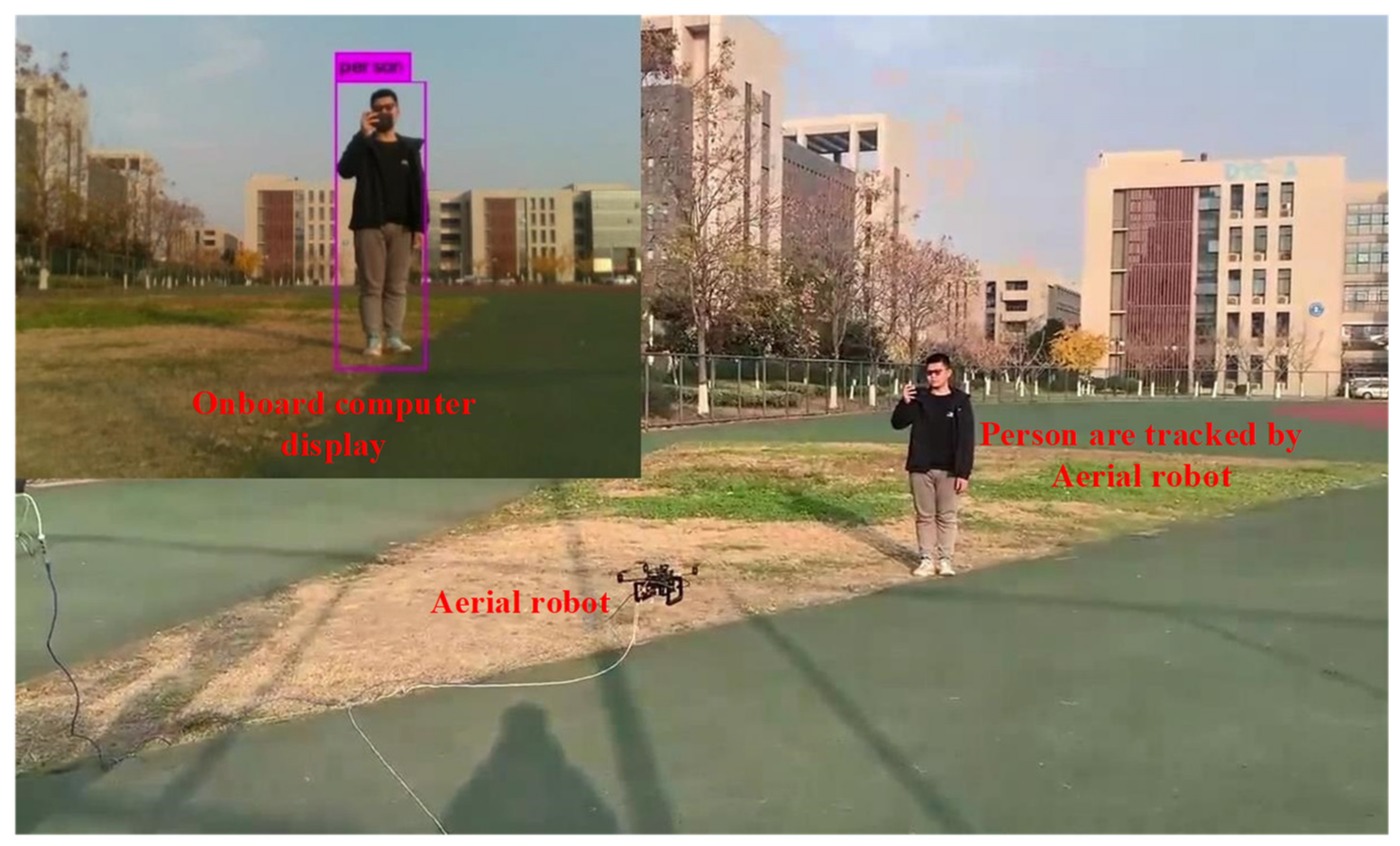
6.3. Real-World Target Tracking
7. Conclusions and Future Work
Author Contributions
Funding
Data Availability Statement
Acknowledgments
Conflicts of Interest
References
- Chen, J.; Li, S.; Liu, D.; Li, X. AiRobSim: Simulating a Multisensor Aerial Robot for Urban Search and Rescue Operation and Training. Sensors 2020, 20, 5223. [Google Scholar] [CrossRef] [PubMed]
- Al-Darraji, I.; Piromalis, D.; Kakei, A.A.; Khan, F.Q.; Stojmenovic, M.; Tsaramirsis, G.; Papageorgas, P.G. Adaptive Robust Controller Design-Based RBF Neural Network for Aerial Robot Arm Model. Electronics 2021, 10, 831. [Google Scholar] [CrossRef]
- Tabib, W.; Goel, K.; Yao, J.; Boirum, C.; Michael, N. Autonomous Cave Surveying with an Aerial Robot. IEEE Trans. Robot. 2021, 9, 1–17. [Google Scholar] [CrossRef]
- Chen, M.; Zhao, H.; Liu, P. Monocular 3D Object Detection Based on Uncertainty Prediction of Keypoints. Machines 2022, 10, 19. [Google Scholar] [CrossRef]
- Sun, P.; Zhang, R.; Jiang, Y.; Kong, T. Sparse R-CNN: End-to-End Object Detection with Learnable Proposals. In Proceedings of the The IEEE/CVF Conference on Computer Vision and Pattern Recognition (CVPR), Nashville, TN, USA, 20–25 June 2021; pp. 14454–14463. [Google Scholar]
- Sun, Z.; Cao, S.; Yang, Y.; Kitani, K. Rethinking Transformer-based Set Prediction for Object Detection. In Proceedings of the IEEE/CVF International Conference on Computer Vision (ICCV), Nashville, TN, USA, 20–25 June 2021; pp. 3611–3620. [Google Scholar]
- Wang, W.; Lai, Q.; Fu, H.; Shen, J.; Ling, H.; Yang, R. Salient Object Detection in the Deep Learning Era: An In-depth Survey. IEEE Trans. Pattern Anal. Mach. Intell. 2021, 1, 1–20. [Google Scholar] [CrossRef] [PubMed]
- Han, S.; Mao, H.; Dally, W. Deep compression: Compressing deep neural networks with pruning trained quantization and huffman coding. In Proceedings of the International Conference on Learning Representations, San Juan, Puerto Rico, 2–4 May 2016. [Google Scholar]
- Lucas, B.D.; Kanade, T. An iterative image registration technique with an application to stereo vision. In Proceedings of the 7th International Joint Conference on Artificial Intelligence, Vancouver, BC, Canada, 24–28 August 1981; pp. 24–28. [Google Scholar]
- Shi, J.; Tomasi. Good features to track. In Proceedings of the IEEE Conference on Computer Vision and Pattern Recognition (CVPR), Seattle, WA, USA, 21–23 June 1994. [Google Scholar]
- Leutenegger, S.; Lynen, S.; Bosse, M.; Siegwart, R.; Furgale, P. Keyframe-based visual–inertial odometry using nonlinear optimization. Int. J. Robot. Res. 2015, 34, 314–334. [Google Scholar] [CrossRef] [Green Version]
- Paul, M.K.; Roumeliotis, S.I. Alternating-Stereo VINS: Observability Analysis and Performance Evaluation. In Proceedings of the IEEE Conference on Computer Vision and Pattern Recognition (CVPR), Salt Lake City, UT, USA, 18–22 June 2018; pp. 4729–4737. [Google Scholar]
- Qin, T.; Li, P.; Shen, S. VINS-Mono: A robust and versatile monocular visual-inertial state estimator. IEEE Trans. Robot. 2018, 34, 1004–1020. [Google Scholar] [CrossRef] [Green Version]
- Rosinol, A.; Abate, M.; Chang, Y.; Carlone, L. Kimera: An Open-Source Library for Real-Time Metric-Semantic Localization and Mapping. In Proceedings of the IEEE International Conference on Robotics and Automation (ICRA), Paris, France, 31 May–31 August 2020; pp. 1689–1696. [Google Scholar] [CrossRef]
- Campos, C.; Elvira, R.; Rodríguez, J.J.G.; Montiel, J.M.M.; Tardós, J.D. ORB-SLAM3: An Accurate Open-Source Library for Visual, Visual–Inertial, and Multimap SLAM. IEEE Trans. Robot. 2021, 37, 1874–1890. [Google Scholar] [CrossRef]
- Forster, C.; Pizzoli, M.; Scaramuzza, D. SVO: Fast semi-direct monocular visual odometry. In Proceedings of the IEEE International Conference on Robotics and Automation (ICRA), Hong Kong, China, 31 May–7 June 2014. [Google Scholar] [CrossRef] [Green Version]
- Engel, J.; Schöps, T.; Cremers, D. LSD-SLAM: Large-Scale Direct Monocular SLAM. In Proceedings of the The European Conference on Computer Vision (ECCV), Zurich, Switzerland, 6–12 September 2014; pp. 834–849. [Google Scholar] [CrossRef] [Green Version]
- Klein, G.; Murray, D. Parallel Tracking and Mapping for Small AR Workspaces. In Proceedings of the IEEE and ACM International Symposium on Mixed and Augmented Reality, Nara, Japan, 13–16 November 2007; pp. 225–234. [Google Scholar] [CrossRef]
- Mur-Artal, R.; Montiel, J.M.M.; Tardós, J.D. ORB-SLAM: A Versatile and Accurate Monocular SLAM System. IEEE Trans. Robot. 2015, 31, 1147–1163. [Google Scholar] [CrossRef] [Green Version]
- Mur-Artal, R.; Tardós, J.D. ORB-SLAM2: An Open-Source SLAM System for Monocular, Stereo, and RGB-D Cameras. IEEE Trans. Robot. 2017, 33, 1255–1262. [Google Scholar] [CrossRef] [Green Version]
- Iandola, F.N.; Han, S.; Moskewicz, M.W. SqueezeNet: AlexNet-level accuracy with 50× fewer parameters and <0.5 MB model size. In Proceedings of the International Conference on Learning Representations (ICLR), Toulon, France, 24–26 April 2017. [Google Scholar]
- Howard, A.G.; Zhu, M.; Chen, B.; Kalenichenko, D.; Wang, W. MobileNets: Efficient Convolutional Neural Networks for Mobile Vision Applications. arXiv 2017, arXiv:1704.04861. [Google Scholar]
- Sandler, M.; Howard, A.; Zhu, M.; Zhmoginov, A.; Chen, L. MobileNetV2: Inverted Residuals and Linear Bottlenecks. In Proceedings of the IEEE Conference on Computer Vision and Pattern Recognition (CVPR), Salt Lake City, UT, USA, 18–22 June 2018; pp. 4510–4520. [Google Scholar]
- Howard, A.; Sandler, M.; Chu, G.; Chen, L.; Chen, B.; Tan, M. Searching for MobileNetV3. In Proceedings of the IEEE/CVF International Conference on Computer Vision (ICCV), Seoul, Korea, 27–28 October 2019; pp. 1314–1324. [Google Scholar]
- Zhang, X.; Zhou, X.; Lin, M.; Sun, J. ShuffleNet: An Extremely Efficient Convolutional Neural Network for Mobile Devices. In Proceedings of the IEEE Conference on Computer Vision and Pattern Recognition (CVPR), Salt Lake City, UT, USA, 18–22 June 2018; pp. 6848–6856. [Google Scholar]
- Ma, N.; Zhang, X.; Zheng, H.; Sun, J. ShuffleNet V2: Practical Guidelines for Efficient CNN Architecture Design. In Proceedings of the European Conference on Computer Vision (ECCV), Munich, Germany, 8–14 September 2018; pp. 116–131. [Google Scholar]
- Huang, G.; Liu, S.; Maaten, L.V. CondenseNet: An Efficient Densenet using Learned Group Convolutions. In Proceedings of the IEEE Conference on Computer Vision and Pattern Recognition (CVPR), Salt Lake City, UT, USA, 18–22 June 2018; pp. 2752–2761. [Google Scholar]
- Qin, T.; Li, P.; Shen, S. Relocalization, Global Optimization and Map Merging for Monocular Visual-Inertial SLAM. In Proceedings of the IEEE International Conference on Robotics and Automation (ICRA), Brisbane, Australia, 21–25 May 2018; pp. 1197–1204. [Google Scholar] [CrossRef] [Green Version]
- Qin, T.; Shen, S. Robust initialization of monocular visual-inertial estimation on aerial robots. In Proceedings of the IEEE/RSJ International Conference on Intelligent Robots and Systems (IROS), Vancouver, BC, Canada, 24–28 September 2017; pp. 4225–4232. [Google Scholar] [CrossRef]
- Lynen, S.; Achtelik, M.W.; Weiss, S.; Chli, M.; Siegwart, R.A. robust and modular multi-sensor fusion approach applied to MAV navigation. In Proceedings of the IEEE/RSJ International Conference on Intelligent Robots and Systems (IROS), Tokyo, Japan, 3–7 November 2013; pp. 3923–3929. [Google Scholar] [CrossRef] [Green Version]
- Redmon, J.; Divvala, S.; Girshick, R.; Farhadi, A. You Only Look Once: Unified, Real-Time Object Detection. In Proceedings of the IEEE Conference on Computer Vision and Pattern Recognition (CVPR), Las Vegas, NV, USA, 27–30 June 2016; pp. 779–788. [Google Scholar]
- Redmon, J.; Farhadi, A. YOLO9000: Better, Faster, Stronger. In Proceedings of the IEEE Conference on Computer Vision and Pattern Recognition (CVPR), Honolulu, HI, USA, 21–26 July 2017; pp. 7263–7271. [Google Scholar]
- Bochkovskiy, A.; Wang, C.; Liao, H.M. YOLOv4: Optimal Speed and Accuracy of Object Detection. arXiv 2020, arXiv:2004.10934. [Google Scholar]
- Itti, L.; Koch, C.; Niebur, E. A model of saliency-based visual attention for rapid scene analysis. IEEE Trans. Pattern Anal. Mach. Intell. 1998, 20, 1254–1259. [Google Scholar] [CrossRef] [Green Version]
- Hu, J.; Shen, L.; Albanie, S.; Sun, G.; Wu, E. Squeeze-and-Excitation Networks. IEEE Trans. Pattern Anal. Mach. Intell. 2020, 42, 2011–2023. [Google Scholar] [CrossRef] [PubMed] [Green Version]
- LeCun, Y.; Boser, B.; Denker, J.S.; Henderson, D.; Howard, R.E.; Hubbard, W.; Jackel, L.D. Backpropagation Applied to Handwritten Zip Code Recognition. Neural Comput. 1989, 1, 541–551. [Google Scholar] [CrossRef]
- Elfwing, S.; Uchibe, E.; Doya, K. Sigmoid-weighted linear units for neural network function approximation in reinforcement learning. Neural Netw. 2018, 107, 3–11. [Google Scholar] [CrossRef] [PubMed]
- Sergey, I.; Christian, S. Batch Normalization: Accelerating Deep Network Training by Reducing Internal Covariate Shift. In Proceedings of the 32nd International Conference on Machine Learning (PMLR), Lille, France, 7–9 July 2015; pp. 448–456. [Google Scholar]
- Singh, S.; Krishnan, S. Filter Response Normalization Layer: Eliminating Batch Dependence in the Training of Deep Neural Networks. In Proceedings of the IEEE/CVF Conference on Computer Vision and Pattern Recognition (CVPR), Seattle, WA, USA, 13–19 June 2020; pp. 11237–11246. [Google Scholar]
- Jégou, H.; Perronnin, F.; Douze, M. Aggregating Local Image Descriptors into Compact Codes. IEEE Trans. Pattern Anal. Mach. Intell. 2011, 34, 1704–1716. [Google Scholar] [CrossRef] [PubMed] [Green Version]
- Perronnin, F.; Dance, C.R. Fisher kernels on visual vocabularies for image categorization. In Proceedings of the IEEE Conference on Computer Vision and Pattern Recognition (CVPR), Minneapolis, MN, USA, 17–22 June 2007. [Google Scholar]
- Burri, M.; Nikolic, J.; Gohl, P.; Schneider, T.; Rehder, J. The EuRoC micro aerial vehicle datasets. Int. J. Robot. Res. 2016, 35, 1157–1163. [Google Scholar] [CrossRef]


| Input | Function Block | Kernel Size | Expansion | Output Channels |
|---|---|---|---|---|
| 224 × 224 × 3 | 3 × 3 convolution | 3 × 3 | - | 16 |
| 112 × 112 × 16 | Reflection residual module | 3 × 3 | 1 | 16 |
| 56 × 56 × 16 | Reflection residual module | 3 × 3 | 4.5 | 24 |
| 28 × 28 × 24 | Reflection residual module | 3 × 3 | 3.7 | 24 |
| 28 × 28 × 24 | Reflection residual module | 3 × 3 | 4 | 40 |
| 14 × 14 × 40 | Reflection residual module | 5 × 5 | 5 | 40 |
| 14 × 14 × 40 | Reflection residual module | 3 × 3 | 6 | 60 |
| 14 × 14 × 60 | Reflection residual module | 5 × 5 | 4 | 60 |
| 14 × 14 × 60 | Reflection residual module | 3 × 3 | 4 | 80 |
| 14 × 14 × 80 | Reflection residual module | 5 × 5 | 6 | 80 |
| 7 × 7 × 80 | Reflection residual module | 5 × 5 | 6 | 100 |
| 7 × 7 × 100 | Reflection residual module | 5 × 5 | 6 | 120 |
| 7 × 7 × 120 | 1 × 1 convolution | 1 × 1 | - | 600 |
| 7 × 7 × 600 | Average pooling | 7 × 7 | - | 600 |
| 1 × 1 × 600 | Full connection layer | - | - | 1200 |
| 1 × 1 × 1200 | Classifier | - | - | 20 |
| Sequence | OKVIS | Kimera-VIO | ORB-SLAM3 | RPEOD | ||||
|---|---|---|---|---|---|---|---|---|
| RMSE | Time | RMSE | Time | RMSE | Time | RMSE | Time | |
| MH01 | 0.16 | 113.8 | 0.15 | 75.6 | 0.07 | 126.4 | 0.16 | 48.6 |
| MH02 | 0.22 | 107.4 | 0.13 | 73.2 | 0.05 | 124.3 | 0.14 | 48.2 |
| MH03 | 0.24 | 105.6 | 0.18 | 73.4 | 0.15 | 121.7 | 0.13 | 46.8 |
| MH04 | 0.34 | 104.8 | 0.27 | 72.6 | 0.12 | 118.5 | 0.23 | 45.2 |
| MH05 | 0.47 | 105.2 | 0.41 | 72.8 | 0.21 | 119.7 | 0.38 | 45.2 |
| V101 | 0.09 | 110.6 | 0.12 | 75.2 | 0.07 | 120.6 | 0.14 | 48.4 |
| V102 | 0.20 | 107.2 | 0.13 | 74.4 | 0.03 | 113.4 | 0.05 | 43.6 |
| V103 | 0.24 | 106.4 | 0.07 | 74.6 | 0.05 | 116.5 | 0.13 | 44.8 |
| V201 | 0.13 | 108.4 | 0.09 | 75.2 | 0.09 | 122.7 | 0.07 | 47.2 |
| V202 | 0.16 | 105.2 | 0.14 | 73.8 | 0.03 | 119.5 | 0.09 | 46.8 |
| V203 | 0.29 | 105.6 | 0.23 | 74.6 | 0.06 | 122.3 | 0.20 | 47.2 |
| Average | 0.23 | 107.2 | 0.17 | 74.1 | 0.09 | 120.5 | 0.15 | 46.5 |
| Detectors | mAP (IoU = 0.5) | mAP (IoU = 0.5:0.95) | Backbone Parameters | Mean FPS (Jetson NX) |
|---|---|---|---|---|
| YOLOV5 | 76.1% | 52.8% | 20.8M | 8.1 |
| YOLOV5-tiny | 72.1% | 45.9% | 6.9M | 15.2 |
| YZNet-YOLOV5 | 76.9% | 55.6% | 28.5M | 7.3 |
| YZNet-YOLOV5-tiny | 66.4% | 38.6% | 1.7M | 23.8 |
Publisher’s Note: MDPI stays neutral with regard to jurisdictional claims in published maps and institutional affiliations. |
© 2022 by the authors. Licensee MDPI, Basel, Switzerland. This article is an open access article distributed under the terms and conditions of the Creative Commons Attribution (CC BY) license (https://creativecommons.org/licenses/by/4.0/).
Share and Cite
Zhang, C.; Yang, Z.; Liao, L.; You, Y.; Sui, Y.; Zhu, T. RPEOD: A Real-Time Pose Estimation and Object Detection System for Aerial Robot Target Tracking. Machines 2022, 10, 181. https://doi.org/10.3390/machines10030181
Zhang C, Yang Z, Liao L, You Y, Sui Y, Zhu T. RPEOD: A Real-Time Pose Estimation and Object Detection System for Aerial Robot Target Tracking. Machines. 2022; 10(3):181. https://doi.org/10.3390/machines10030181
Chicago/Turabian StyleZhang, Chi, Zhong Yang, Luwei Liao, Yulong You, Yaoyu Sui, and Tang Zhu. 2022. "RPEOD: A Real-Time Pose Estimation and Object Detection System for Aerial Robot Target Tracking" Machines 10, no. 3: 181. https://doi.org/10.3390/machines10030181
APA StyleZhang, C., Yang, Z., Liao, L., You, Y., Sui, Y., & Zhu, T. (2022). RPEOD: A Real-Time Pose Estimation and Object Detection System for Aerial Robot Target Tracking. Machines, 10(3), 181. https://doi.org/10.3390/machines10030181