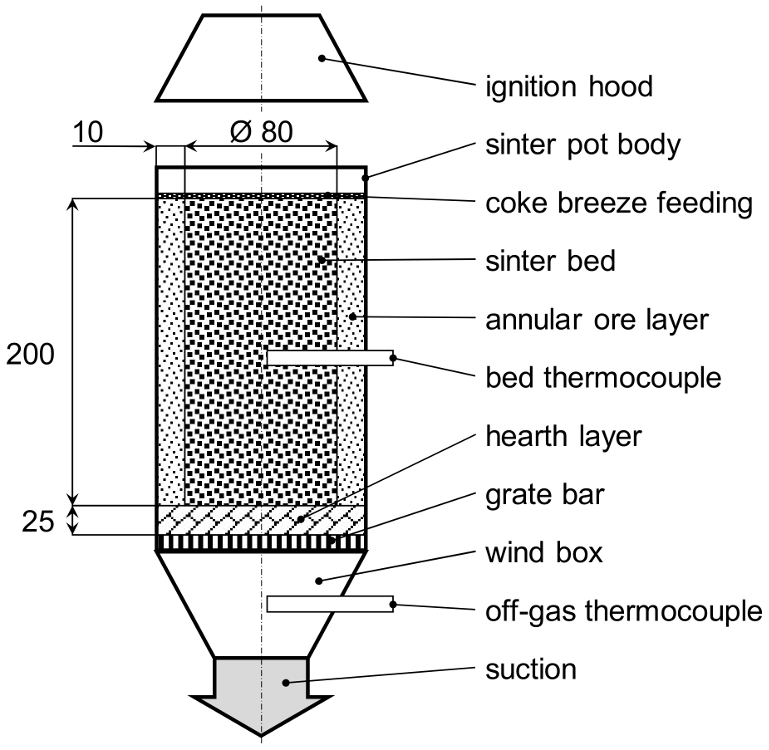
Figure 1.
Sinter pot arrangement (dimensions in mm).
Figure 1.
Sinter pot arrangement (dimensions in mm).
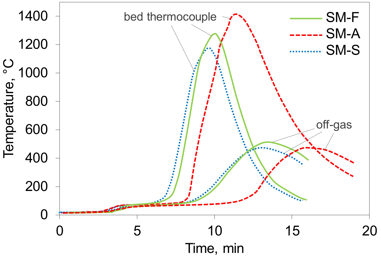
Figure 2.
Temperature profiles recorded during pot sintering. Higher curves apply for the thermocouple in bed and lower for off-gas.
Figure 2.
Temperature profiles recorded during pot sintering. Higher curves apply for the thermocouple in bed and lower for off-gas.
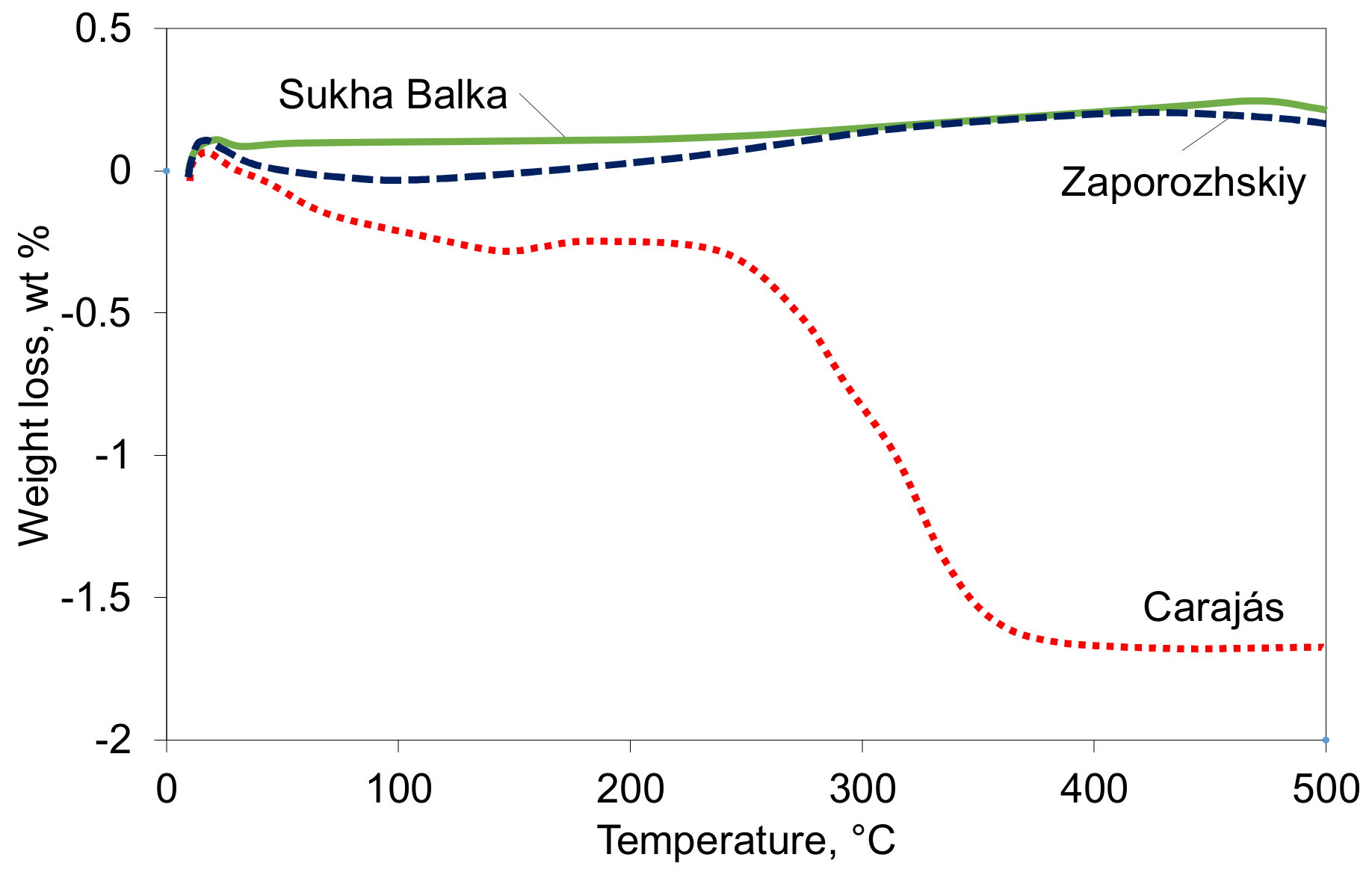
Figure 3.
Characterization of the studied iron ores with TG analysis.
Figure 3.
Characterization of the studied iron ores with TG analysis.
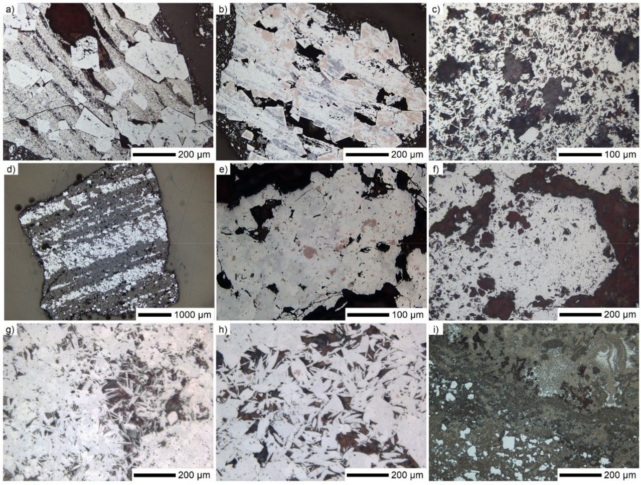
Figure 4.
Reflected light micrographs of iron ores: (a–c) Carajás, (d–f) Sukha Balka, and (g–i) Zaporozhskiy.
Figure 4.
Reflected light micrographs of iron ores: (a–c) Carajás, (d–f) Sukha Balka, and (g–i) Zaporozhskiy.
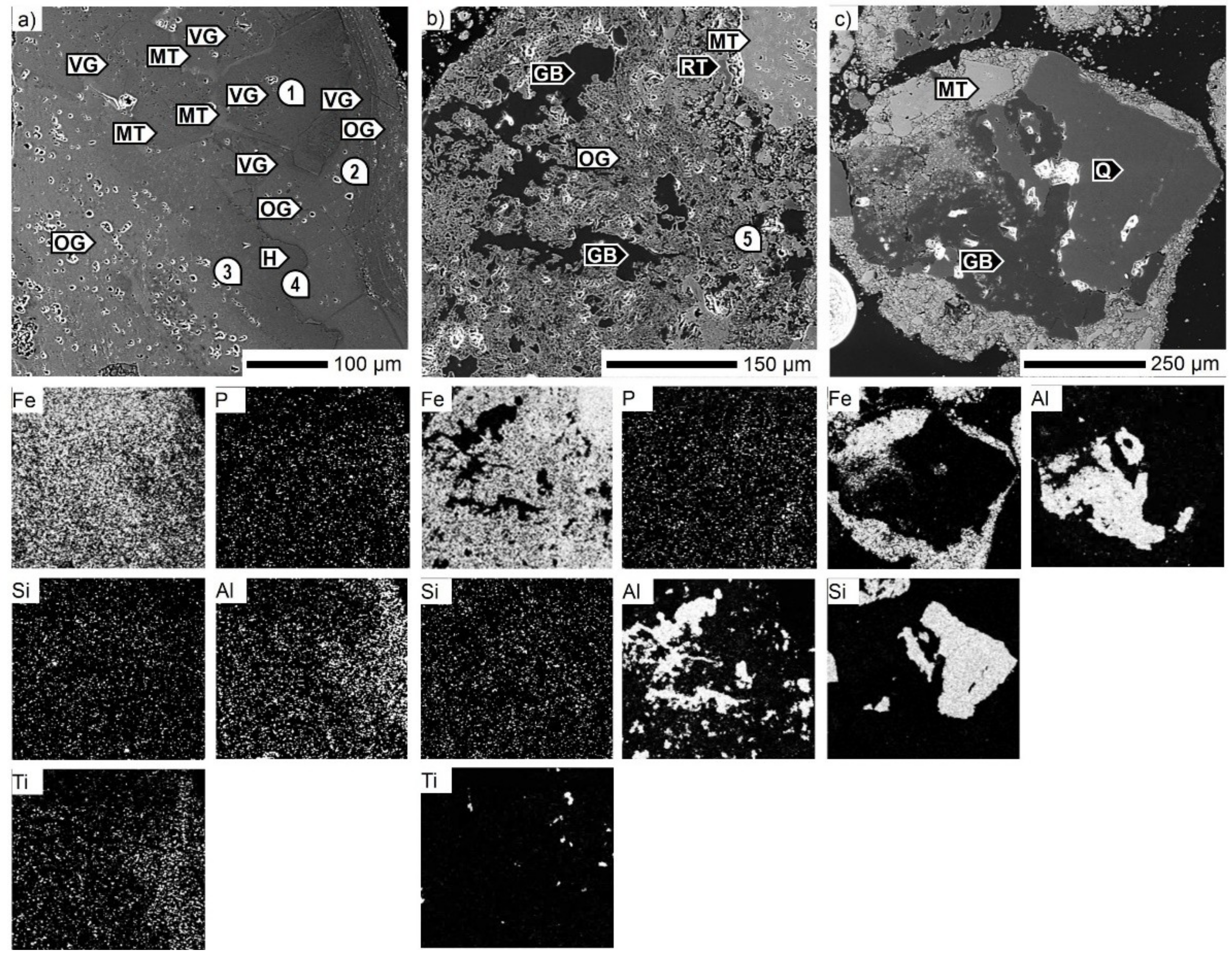
Figure 5.
SEM micrographs of the Carajás ore particles. GB: gibbsite, H: hematite (microporous), MT: martite, OG: ochreous goethite, Q: quartz, RT: rutile, VG: vitreous goethite, 1–5—see
Table 4.
Figure 5.
SEM micrographs of the Carajás ore particles. GB: gibbsite, H: hematite (microporous), MT: martite, OG: ochreous goethite, Q: quartz, RT: rutile, VG: vitreous goethite, 1–5—see
Table 4.
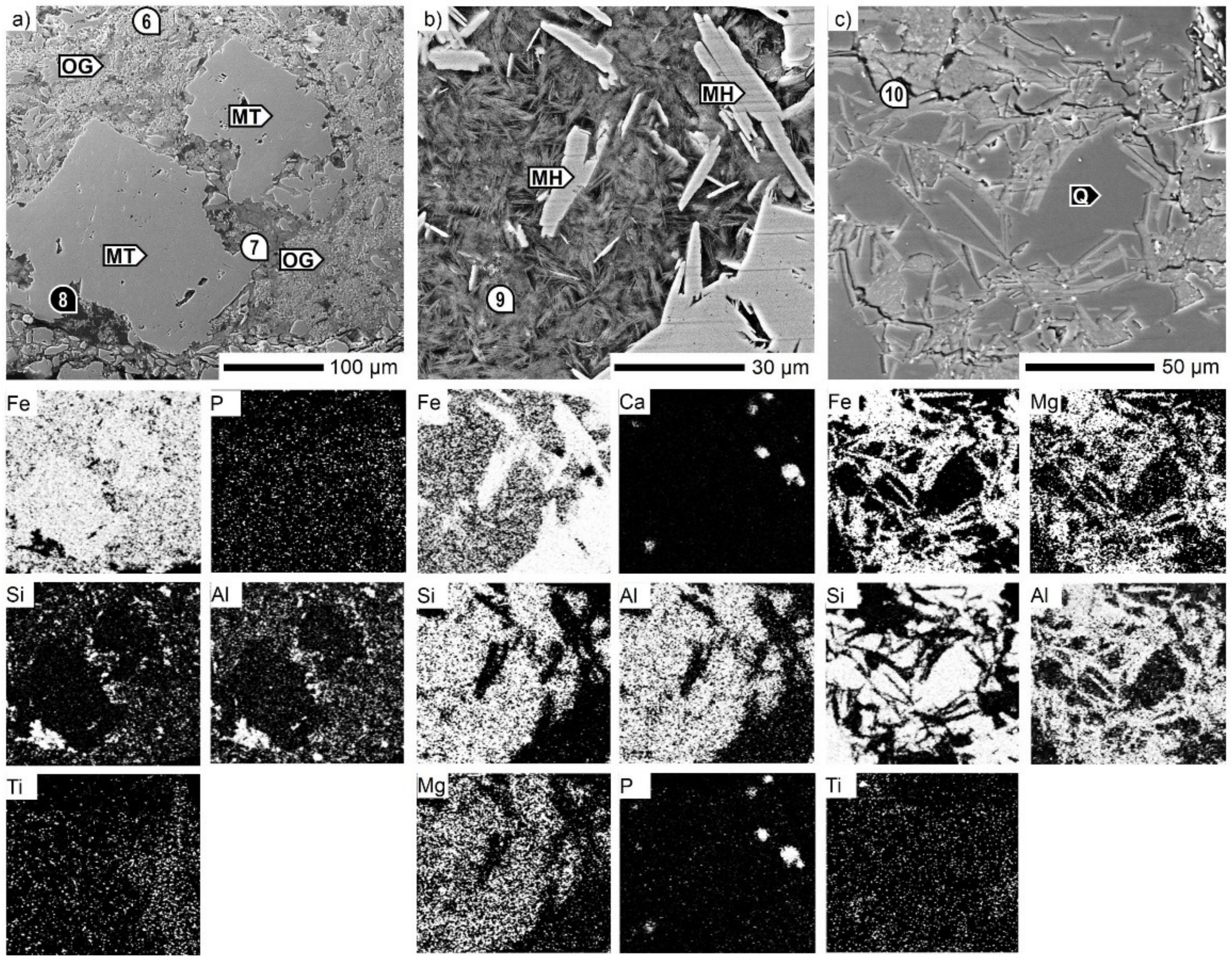
Figure 6.
SEM micrographs of the (
a) Sukha Balka ore (
b) and (
c) Zaporozhskiy ore. MH: microplaty hematite, MT: martite, OG: ochreous goethite, Q: quartz, 6–10—see
Table 5.
Figure 6.
SEM micrographs of the (
a) Sukha Balka ore (
b) and (
c) Zaporozhskiy ore. MH: microplaty hematite, MT: martite, OG: ochreous goethite, Q: quartz, 6–10—see
Table 5.
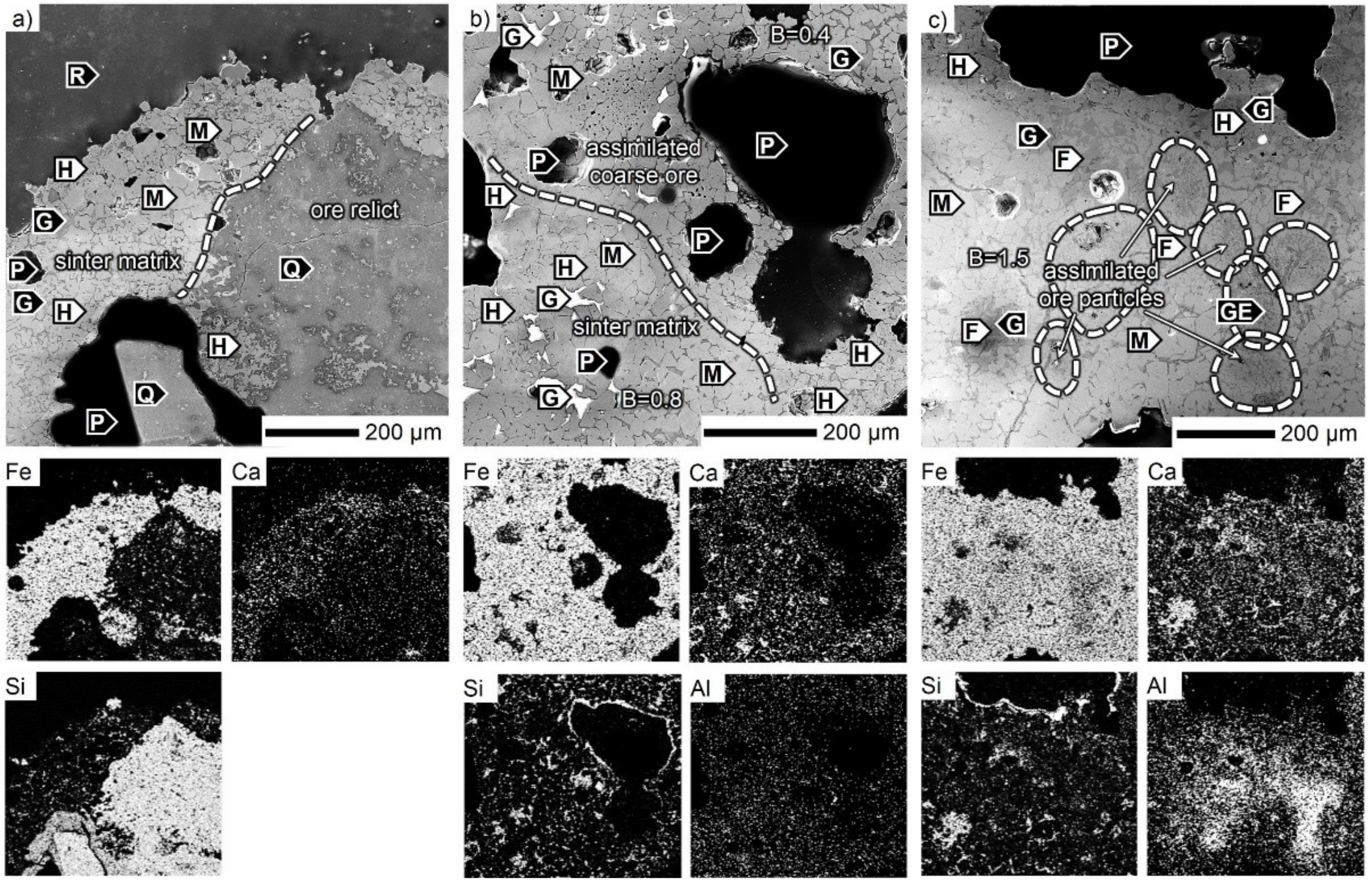
Figure 7.
SEM micrographs of the SM-F sinter. B: CaO/SiO2, F: SFCA, G: glass, GE: gehlenite, H: hematite, M: magnetite, P: pore, Q: quartz, R: resin.
Figure 7.
SEM micrographs of the SM-F sinter. B: CaO/SiO2, F: SFCA, G: glass, GE: gehlenite, H: hematite, M: magnetite, P: pore, Q: quartz, R: resin.
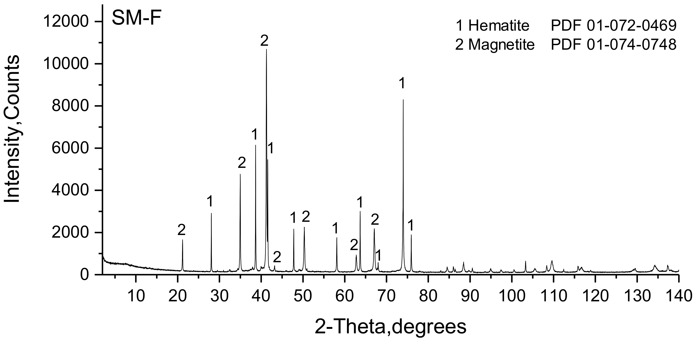
Figure 8.
Powder diffractogram of the SM-F sinter.
Figure 8.
Powder diffractogram of the SM-F sinter.
Figure 9.
SEM micrographs of the SM-A sinter. B: CaO/SiO2, F: SFCA, G: glass, H: hematite, M: magnetite, P: pore, W: wüstite.
Figure 9.
SEM micrographs of the SM-A sinter. B: CaO/SiO2, F: SFCA, G: glass, H: hematite, M: magnetite, P: pore, W: wüstite.
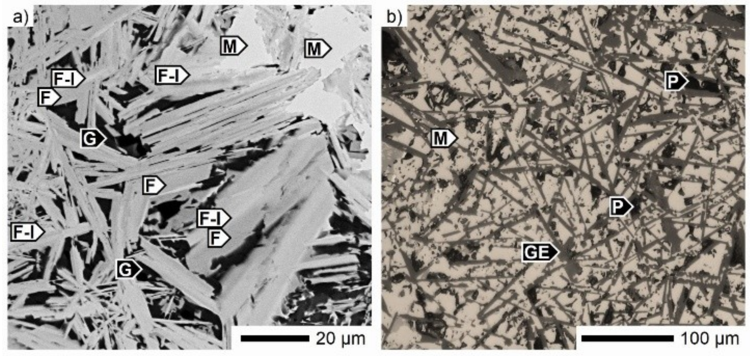
Figure 10.
Micrographs of the SM-A sinter microstructure: (a) calcium ferrites assemblage (SEM) and (b) magnetite-gehlenite (reflected light). F: SFCA, F-I: SFCA-I, G: glass, GE: gehlenite M: magnetite, P: pore.
Figure 10.
Micrographs of the SM-A sinter microstructure: (a) calcium ferrites assemblage (SEM) and (b) magnetite-gehlenite (reflected light). F: SFCA, F-I: SFCA-I, G: glass, GE: gehlenite M: magnetite, P: pore.
Figure 11.
Powder difractogram of the SM-A sinter.
Figure 11.
Powder difractogram of the SM-A sinter.
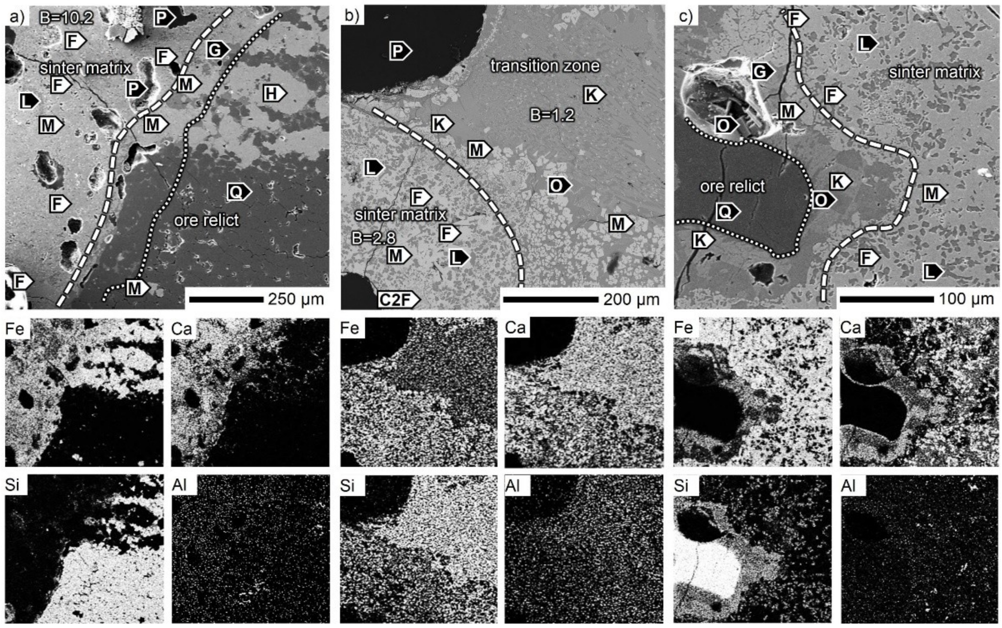
Figure 12.
SEM micrographs of the SM-S sinter. B—CaO/SiO2, C2F—dicalcium ferrite, F—SFCA, G—glass, H—hematite, K—kirschsteinite, L—larnite, M—magnetite, O—Fe–Ca-olivine, P—pore, Q—quartz.
Figure 12.
SEM micrographs of the SM-S sinter. B—CaO/SiO2, C2F—dicalcium ferrite, F—SFCA, G—glass, H—hematite, K—kirschsteinite, L—larnite, M—magnetite, O—Fe–Ca-olivine, P—pore, Q—quartz.
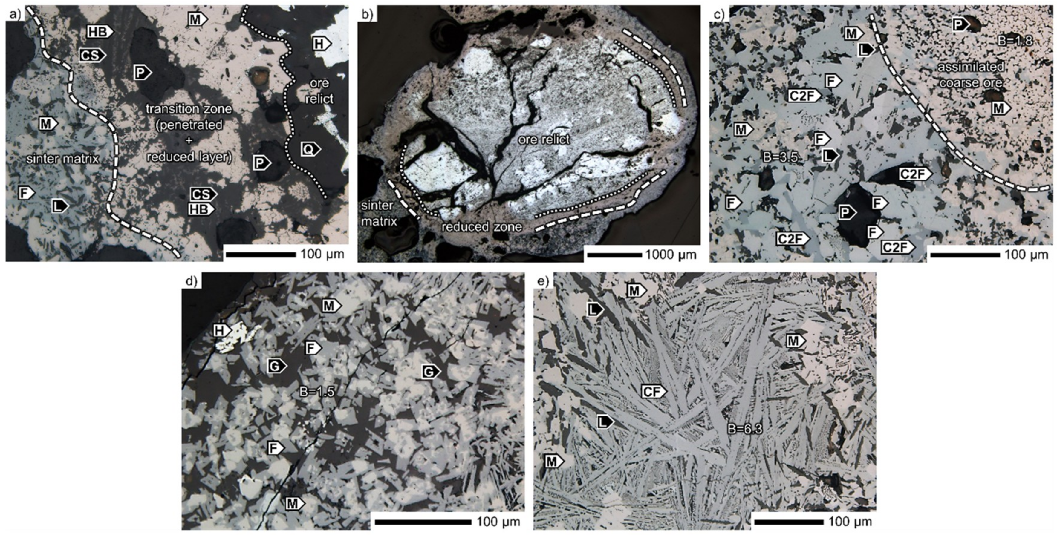
Figure 13.
Reflected light micrographs of the SM-S sinter. B: CaO/SiO2, CF: monocalcium ferrite, CS: pseudowollatonite, C2F: dicalcium ferrite, F: SFCA, G: glass, H: hematite, L: larnite, M: magnetite, P: pore, Q: quartz.
Figure 13.
Reflected light micrographs of the SM-S sinter. B: CaO/SiO2, CF: monocalcium ferrite, CS: pseudowollatonite, C2F: dicalcium ferrite, F: SFCA, G: glass, H: hematite, L: larnite, M: magnetite, P: pore, Q: quartz.
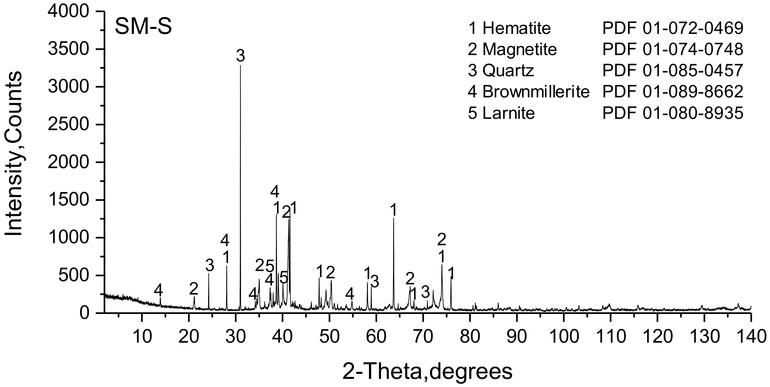
Figure 14.
Powder diffractogram of the SM-S sinter.
Figure 14.
Powder diffractogram of the SM-S sinter.
Figure 15.
Granule structure within different mixtures.
Figure 15.
Granule structure within different mixtures.
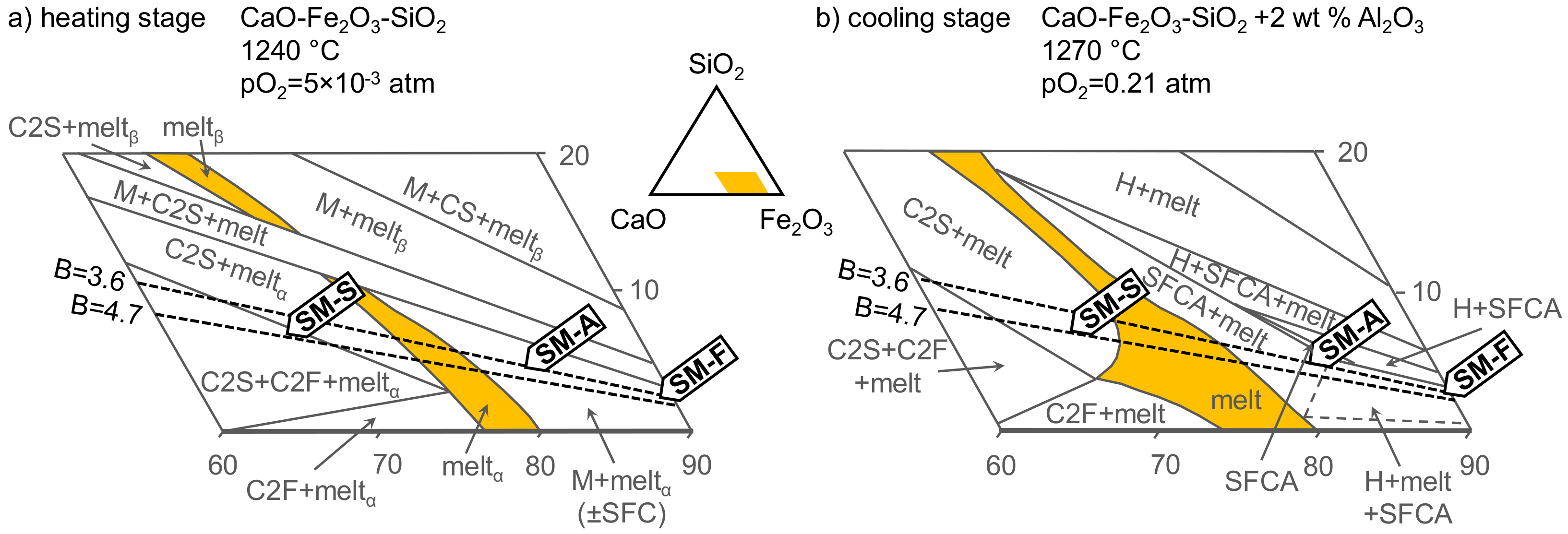
Figure 16.
Adhering fines of SM-F, SM-A, and SM-S mixtures, according to chemical composition plotted into the CaO–Fe
2O
3–SiO
2 phase diagram’s isothermal sections. Section (
a) CaO–Fe
2O
3–SiO
2 system at 1240 °C and oxygen partial pressure pO
2 = 5 × 10
−3 atm. Section (
b) CaO–Fe
2O
3–SiO
2 system with 2 wt % Al
2O
3 at 1270 °C in air. Abbreviations denote: M: magnetite, H: hematite, SFC: silicoferrite of calcium (solid solution), C2F: dicalcium ferrite, C2S: Ca
2SiO
4, CS: CaSiO
3. In the sections, dashed lines mark the useful basicity. Compositional range in wt %. Diagrams adapted from Pownceby and Clout [
36].
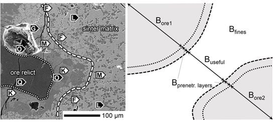
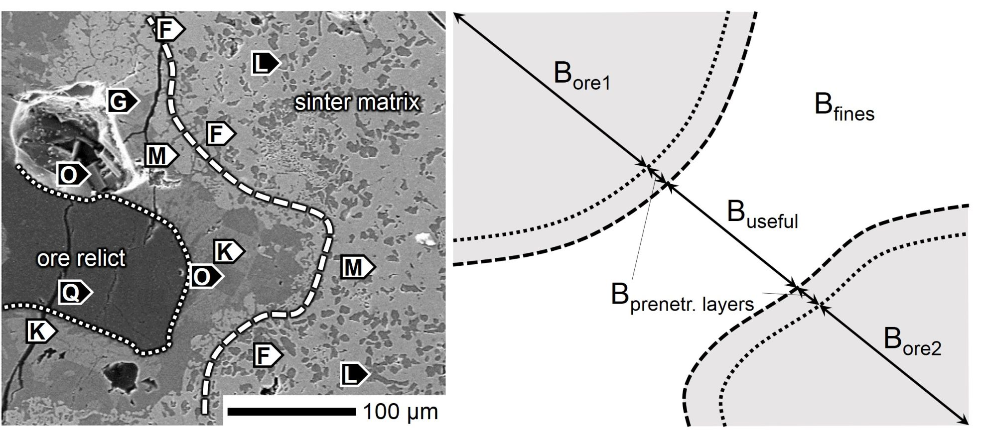
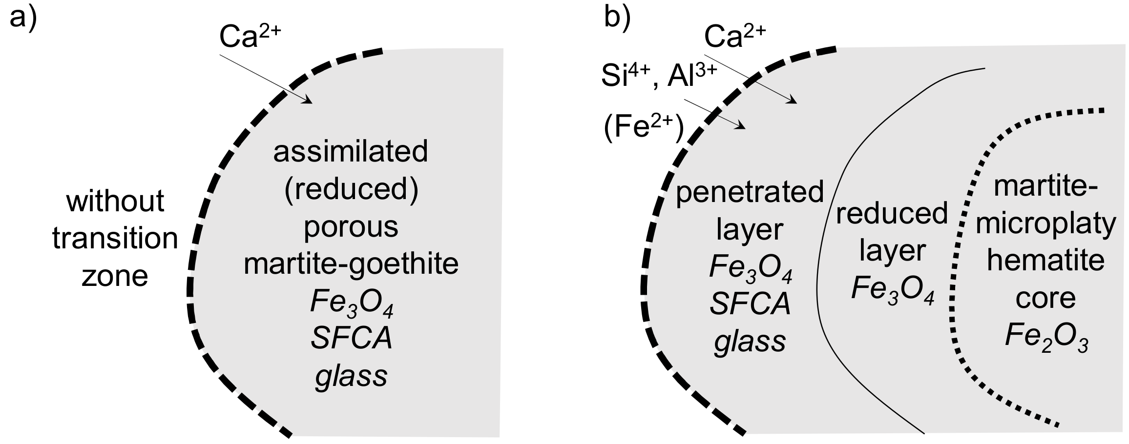
Figure 17.
Ore assimilation scheme in the SM-F sinter.
Figure 17.
Ore assimilation scheme in the SM-F sinter.
Figure 18.
Ore assimilation scheme in SM-A sinter.
Figure 18.
Ore assimilation scheme in SM-A sinter.
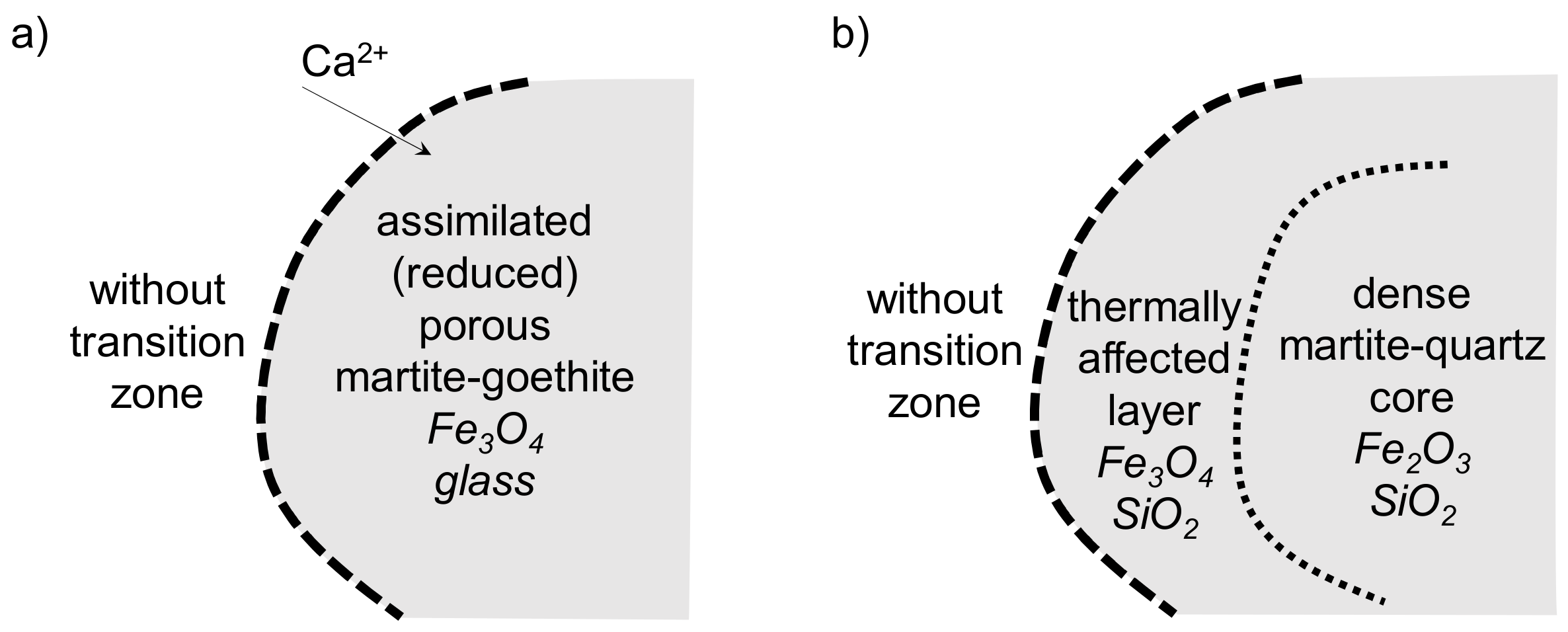
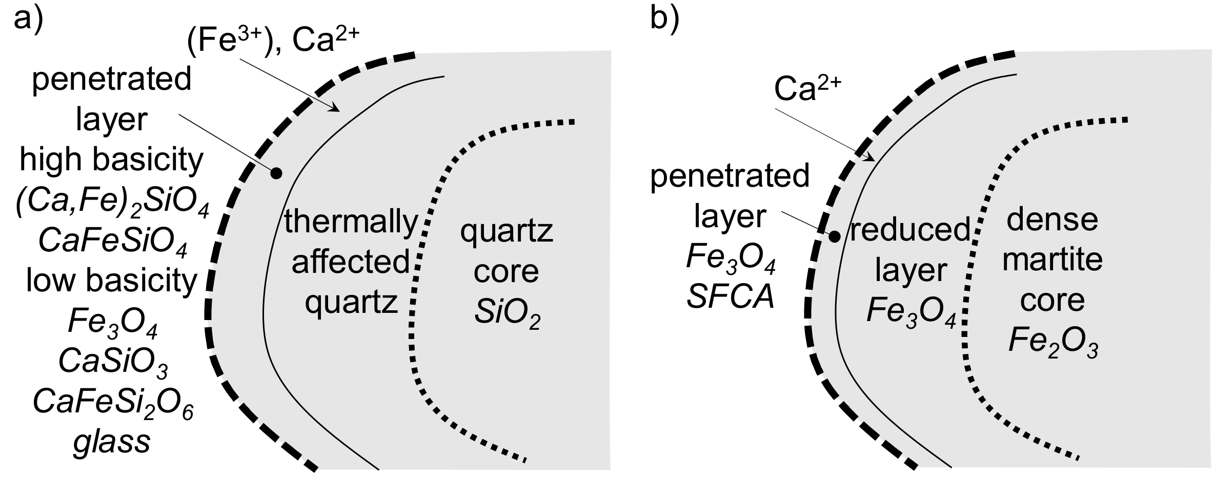
Figure 19.
Ore assimilation scheme in the SM-S sinter.
Figure 19.
Ore assimilation scheme in the SM-S sinter.
Figure 20.
Detailed view on the powder diffractogram of the SM-S sinter. The solid red triangles mark the positions of SFCA covered under diffraction patterns of other phases and the blank triangles mark the positions of SFCA, where SFCA patterns are missing in the sample.
Figure 20.
Detailed view on the powder diffractogram of the SM-S sinter. The solid red triangles mark the positions of SFCA covered under diffraction patterns of other phases and the blank triangles mark the positions of SFCA, where SFCA patterns are missing in the sample.
Table 1.
Chemical composition of the raw materials, dry wt %.
Table 1.
Chemical composition of the raw materials, dry wt %.
| Component | Carajás | Sukha Balka | Zaporozhskiy | Limestone | Coke Ash |
|---|
| Fetotal | 65.15 | 61.94 | 62.41 | NA | 19.02 |
| FeO | 0.26 | 0.30 | 1.15 | NA | 0.00 |
| Fe2O3 | 92.86 | 88.22 | 87.96 | 0.00 | 27.20 |
| CaO | 0.06 | 0.10 | 0.69 | 46.37 | 6.80 |
| SiO2 | 1.40 | 10.28 | 8.54 | 2.51 | 34.70 |
| Al2O3 | 0.67 | 0.77 | 1.09 | 1.30 | 21.10 |
| MgO | 0.11 | 0.10 | 0.32 | 4.28 | 2.80 |
| TiO2 | 0.18 | 0.01 | 0.01 | NA | 0.00 |
| Na2O | 0.03 | 0.11 | 0.07 | NA | 1.10 |
| K2O | 0.03 | 0.05 | 0.05 | NA | 1.60 |
| Mn | 0.54 | 0.02 | 0.05 | NA | 0.12 |
| P | 0.02 | 0.02 | 0.05 | NA | 0.36 |
| S | 0.01 | 0.01 | 0.02 | NA | NA |
| LOI * | 7.50 | 2.00 | 1.00 | 42.25 | - |
Table 2.
Chemical composition of iron ores, according to their size distributions in mm, dry wt %.
Table 2.
Chemical composition of iron ores, according to their size distributions in mm, dry wt %.
| Ore | Fraction | Fraction Ratio | Fetotal | CaO | SiO2 | Al2O3 | MgO |
|---|
| Carajás | +8 | 9.37 | 62.63 | 0.62 | 1.30 | 0.95 | 1.02 |
| 6.3–8 | 5.54 | 60.78 | 1.72 | 1.81 | 3.02 | 0.49 |
| 5–6.3 | 4.34 | 62.71 | 0.24 | 1.52 | 0.85 | 0.71 |
| 3.15–5 | 11.31 | 65.62 | 0.25 | 1.54 | 0.64 | 0.40 |
| 2–3.15 | 4.80 | 64.26 | 0.21 | 1.43 | 0.53 | 0.51 |
| 1–2 | 14.17 | 67.55 | 0.15 | 0.66 | 0.66 | 0.43 |
| 0.5–1 | 15.58 | 65.78 | 0.27 | 1.30 | 0.89 | 0.31 |
| 0.25–0.5 | 10.99 | 67.12 | 0.20 | 0.77 | 1.00 | 0.56 |
| 0.125–0.25 | 11.37 | 67.45 | 0.10 | 0.93 | 1.08 | 0.21 |
| 0.063–0.125 | 4.02 | 68.36 | 0.08 | 0.85 | 1.04 | 0.16 |
| –0.063 | 8.51 | 68.01 | 0.10 | 0.89 | 1.15 | 0.22 |
| Sukha Balka | +8 | 11.95 | 48.41 | 0.07 | 17.40 | 0.75 | 0.73 |
| 6.3–8 | 10.69 | 54.69 | 0.08 | 15.50 | 0.87 | 0.67 |
| 5–6.3 | 5.25 | 59.13 | 0.08 | 14.10 | 0.75 | 0.49 |
| 3.15–5 | 7.06 | 60.46 | 0.10 | 11.04 | 0.78 | 0.52 |
| 2–3.15 | 6.16 | 59.52 | 0.09 | 12.52 | 0.69 | 0.61 |
| 1–2 | 10.32 | 62.84 | 0.08 | 8.60 | 0.79 | 0.50 |
| 0.5–1 | 7.39 | 63.05 | 0.11 | 7.87 | 0.98 | 0.41 |
| 0.25–0.5 | 8.61 | 64.58 | 0.11 | 6.49 | 1.72 | 0.36 |
| 0.125–0.25 | 10.08 | 64.29 | 0.12 | 6.85 | 1.61 | 0.31 |
| 0.063–0.125 | 9.25 | 64.19 | 0.15 | 6.94 | 1.11 | 0.27 |
| −0.063 | 13.23 | 65.31 | 0.13 | 4.78 | 0.91 | 0.44 |
| Zaporozhskiy | +8 | 11.51 | 59.42 | 0.15 | 8.80 | 0.99 | 0.71 |
| 6.3–8 | 5.42 | 58.34 | 0.28 | 9.10 | 0.82 | 0.68 |
| 5–6.3 | 6.32 | 58.81 | 0.24 | 9.17 | 0.83 | 0.60 |
| 3.15–5 | 9.93 | 60.88 | 0.30 | 9.51 | 1.04 | 0.80 |
| 2–3.15 | 9.03 | 59.14 | 0.24 | 8.35 | 0.84 | 0.63 |
| 1–2 | 15.57 | 60.19 | 0.40 | 8.20 | 1.03 | 0.90 |
| 0.5–1 | 9.07 | 61.48 | 0.41 | 7.56 | 1.38 | 0.51 |
| 0.25–0.5 | 8.91 | 60.86 | 0.75 | 7.00 | 1.55 | 0.51 |
| 0.125–0.25 | 9.57 | 62.63 | 0.73 | 5.45 | 1.51 | 0.48 |
| 0.063–0.125 | 6.13 | 63.66 | 0.89 | 5.45 | 1.40 | 0.35 |
| −0.063 | 8.55 | 63.36 | 0.91 | 5.78 | 1.46 | 0.42 |
Table 3.
Sintering mixtures blending scheme, wt %.
Table 3.
Sintering mixtures blending scheme, wt %.
| Mixture | Carajás | Sukha Balka | Zaporozhskiy | Alumina | Limestone | Coke |
|---|
| SM-F | 74.0 | - | 10.0 | - | 10.0 | 6.0 |
| SM-A | 49.2 | - | 24.0 | 3.0 | 15.0 | 8.8 |
| SM-S | - | 62.5 | - | - | 31.5 | 6.0 |
Table 4.
EDS analysis from
Figure 5, wt %.
Table 4.
EDS analysis from
Figure 5, wt %.
| Point | Fe2O3 | SiO2 | Al2O3 | TiO2 | P2O5 | Phase |
|---|
| 1 | 98.3 | 1.1 | 0.3 | - | 0.3 | vitreous goethite |
| 2 | 86.6 | 0.6 | 5.8 | 4.1 | 2.9 | vitreous goethite |
| 3 | 96.7 | 1.2 | 1.0 | - | 1.1 | ochreous goethite |
| 4 | 92.7 | 0.6 | 3.0 | - | 3.7 | ochreous goethite |
| 5 | 96.6 | 0.6 | 1.3 | 0.7 | 0.8 | ochreous goethite |
Table 5.
EDS analysis from
Figure 6, wt %.
Table 5.
EDS analysis from
Figure 6, wt %.
| Point | Fe2O3 | SiO2 | Al2O3 | MgO | Phase |
|---|
| 6 | 94.3 | 2.9 | 2.8 | - | ochreous goethite * |
| 7 | 96.7 | 2.1 | 1.2 | - | ochreous goethite * |
| 8 | 1.9 | 53.4 | 44.7 | - | kaolinite |
| 9 | 41.0 | 28.9 | 20.7 | 9.3 | chlorite |
| 10 | 35.5 | 32.7 | 21.1 | 10.7 | chlorite |
Table 6.
Average chemical composition of the secondary phases in SM-F sinter, wt %.
Table 6.
Average chemical composition of the secondary phases in SM-F sinter, wt %.
| Phase | Fe2O3 | CaO | SiO2 | Al2O3 | MgO | TiO2 | K2O | P2O5 | FeO |
|---|
| magnetite | 99.1 | 0.3 | 0.4 | 0.3 | 0.2 | - | - | - | - |
| hematite | 99.8 | - | 0.2 | - | - | - | - | - | - |
| SFCA | 64.9 | 15.9 | 6.1 | 13.1 | - | - | - | - | - |
| glass | - | 36.6 | 37.2 | 6.2 | - | 1.5 | 0.3 | 1.1 | 17.2 |
Table 7.
Average chemical composition of the secondary phases in SM-A sinter, wt %.
Table 7.
Average chemical composition of the secondary phases in SM-A sinter, wt %.
| Phase | Fe2O3 | CaO | SiO2 | Al2O3 | MgO | TiO2 | K2O | Na2O | P2O5 | FeO |
|---|
| magnetite * | 94.8 | 1.7 | - | 2.4 | 1.0 | - | - | - | - | - |
| wüstite | - | 0.5 | - | 0.5 | 1.2 | - | - | - | - | 97.9 |
| hematite | 98.6 | - | - | 1.4 | - | - | - | - | - | - |
| SFCA (a) * | 70.5 | 16.9 | 6.0 | 6.5 | 0.1 | 0.1 | - | - | - | - |
| SFCA (b) * | 64.8 | 15.0 | 8.0 | 10.6 | - | - | - | - | - | - |
| SFCA-I * | 80.9 | 11.0 | 1.9 | 4.8 | 1.0 | - | - | - | - | - |
| glass (a) | - | 42.7 | 33.4 | 4.3 | - | 1.6 | 1.7 | 0.3 | 2.4 | 13.0 |
| glass (b) | - | 42.3 | 17.5 | 19.5 | - | - | - | - | - | 20.7 |
Table 8.
Average chemical composition of the secondary phases in the SM-S sinter, wt %.
Table 8.
Average chemical composition of the secondary phases in the SM-S sinter, wt %.
| Phase | Fe2O3 | CaO | SiO2 | Al2O3 | MgO | TiO2 | P2O5 | FeO |
|---|
| magnetite | 95.4 | 1.9 | 0.1 | 1.1 | 1.6 | - | - | - |
| monocalcium ferrite | 72.8 | 26.4 | 0.0 | 0.7 | - | - | - | - |
| dicalcium ferrite | 50.0 | 44.3 | 3.0 | 2.4 | - | 0.2 | - | - |
| SFCA-I | 82.5 | 13.2 | 0.4 | 1.6 | 2.2 | - | - | - |
| SFCA (a) | 79.3 | 19.5 | 0.0 | 0.4 | 0.7 | - | - | - |
| SFCA (b) | 69.1 | 18.6 | 7.6 | 3.8 | 0.7 | - | - | - |
| larnite | - | 65.6 | 30.2 | 0.0 | 0.0 | - | 0.1 | 4.0 |
| iron-calcium olivine * | - | 40.4 | 34.1 | 5.4 | 1.3 | - | - | 18.7 |
| Glass * | - | 45.8 | 35.7 | 3.3 | 0.5 | 0.2 | - | 14.6 |
Table 9.
Estimated chemical composition of the adhering layers, wt %.
Table 9.
Estimated chemical composition of the adhering layers, wt %.
| Mixture | Fetotal | CaO | SiO2 | Al2O3 | CaO/SiO2 |
|---|
| SM-F | 57.6 | 9.7 | 2.7 | 1.6 | 3.6 |
| SM-A | 48.2 | 14.7 | 3.9 | 8.1 | 3.7 |
| SM-S | 39.8 | 29.8 | 6.3 | 2.0 | 4.7 |


