Abstract
A highly sensitive Fabry–Pérot interferometer (FPI) is fabricated via symmetric taper fiber cleaving and centered waist-inserted assembly, a design where geometric symmetry is fundamental to the sensor’s performance. The FPI is fabricated by simple and cost-effective techniques, including fiber cleaving, splicing, and tapering. Due to the ultra-long cantilever beam with an effective length of 2.33 mm and the ultra-short Fabry–Pérot (FP) cavity with an actual length of 13.98 μm, the sensor exhibits an ultra-high strain sensitivity of 544.57 pm/με in experimental results. The sensor boasts a small temperature sensitivity of 1.02 pm/°C and a cross-temperature sensitivity of 0.0019 µε/°C in the temperature range of 25–200 °C. Furthermore, the sensor has good stability and repeatability. Owing to the symmetry-enhanced design, simple fabrication process, high strain sensitivity, as well as a stable, linearly proportional response over an extensive strain regime, the device has large potential in various sensing applications.
1. Introduction
Optical fiber-based strain sensors have garnered much industrial and research interest for strain measurement due to their excellent durability and stability as well as versatile applications such as military systems, medical monitoring, aerospace components, structural engineering, and civil engineering [1,2,3,4,5,6,7,8]. For instance, optical fiber strain sensors are capable of monitoring strain variations under flowing fluid conditions, enabling applications in reservoirs. They can be used to monitor strain variations associated with the geological storage of carbon dioxide and offer timely detection of abnormal strain changes due to carbon dioxide leakage. Different types of optical fiber structures have been proposed for strain sensing, including fiber Bragg gratings [9,10], Mach–Zehnder interferometers (MZIs) [11,12,13], optical fiber FPI [14,15], photonic crystal fibers [16,17,18], and optical fiber surface plasmon resonance [19,20]. These structures are quite attractive on account of their resistance to electromagnetic interference, stability, cost-effectiveness, compactness, as well as high sensitivity.
There are several methods and designs for optical fiber sensors consisting of inline FP micro-cavities with enhanced sensitivity [21,22,23]. Theoretically [24], the strain sensitivity of the fiber inline FP micro-cavity depends on the shape and dimension of the micro-cavity. Consequently, FPI sensors containing micro-cavities of different shapes, such as oblate spheroid, narrow cuboid, and expanded bubble, have been proposed [25]. For example, Li et al. developed an FPI strain sensor featuring a rounded-rectangle air gap, which exhibits a strain sensitivity of 8 pm/µε [26]. Liu et al. reported a fiber-optic strain sensor employing a crescent-shaped Fabry–Perot fiber cavity geometry, featuring a strain sensitivity of 9.67 pm/µε [27]. Cai et al. have proposed an FPI composed of an asymmetrical air-microbubble structure with an ultrathin wall showing a maximum sensitivity of 10.15 pm/µε [28]. Notably, the integration of microspheres into the sensor fiber represents an effective approach to enhancing strain sensitivity. Nevertheless, the sensitivities of the aforementioned fiber inline FP micro-cavities are only 10–30 pm/µɛ, and further improvement is required before commercial acceptance.
An alternative approach to boost the strain sensitivity of inline fiber FPI micro-cavities entails decoupling the active length of the cavity from the FP interference and subsequently increasing the active length. An air cavity FPI with a cantilever beam structure that incorporates quartz capillaries or hollow optical fibers has been proposed to extend the length of the strain action, amplify axial strain, and attain high strain sensitivity and low temperature sensitivity [29,30]. However, these sensors often suffer from compromised structural dimensions, stability, and tensile strength. To address these limitations, an inline fiber-optic strain sensor incorporating an FP micro-cavity with extended active length has been developed [31]. Nonetheless, it is important to note that as the active length increases, the etching process may affect the thickness of the outer wall and the diameter of the inner taper, thereby potentially impacting the properties of the sensor.
This study demonstrates a symmetry-optimized strain sensor that exploits symmetric taper fiber cleaving, a key fabrication step designed to achieve a geometrically balanced, centered waist-inserted FPI structure, which features an ultra-long 2.33 mm cantilever beam and ultra-short 13.98 μm FP cavity. Precise symmetry is crucial for achieving optimal alignment and mode matching in interferometric configurations, directly impacting sensitivity and stability. The structure is fabricated by a simple and cost-effective process involving fiber cleaving, tapering, and splicing. Experimental results disclose an ultra-high strain sensitivity of 544.57 pm/με. The FPI micro-cavity with a capillary-taper structure exhibits good sensing linearity. In the temperature range from 25 to 200 °C, the temperature and cross-temperature sensitivities are 1.02 pm/°C and 0.0019 µε/°C, respectively, and the smaller errors are attributable to temperature fluctuations. The sensor shows remarkable stability and repeatability experimentally. In oil extraction, it monitors high-pressure pipelines (welds, flanges) and machinery for leaks/corrosion via sub-micrometer strain detection. For structures, it measures dynamic (traffic/wind) and static (settlement/creep) strains in bridges/buildings, resolving nanometer-scale vibrations with high repeatability.
2. Sensor Fabrication and Working Principles
The fabrication process of the symmetry-optimized FPI micro-cavity with a capillary-taper structure is depicted in Figure 1. The single-mode fiber (SMF) was placed on the optical fiber tapering system (Idealphotonics, IPCS-5000-SMT, Shenzhen, China) as shown in Figure 1a. As shown in Figure 1b, the SMF is tapered via a two-stage process involving fiber clamp pulling distances of 0–4 mm and 4–20 mm, pulling speeds of 0.6 mm/s and 1 mm/s, a hydrogen flow rate of 147 sccm, a hydrogen torch heating width of 8 mm, and a torch scanning distance of 2.4 mm, resulting in a tapered fiber. The waist diameter of the tapered fiber is between 60 μm and 70 μm, exhibiting high rotational symmetry. The distance from the waist of the tapered fiber to the position where its diameter reaches 100 μm is approximately 2 to 3 mm. The taper was then cut off in the middle to form a taper fiber tip using a fiber cleaver, as shown in Figure 1c. As shown in Figure 1d, an SMF with a planar endface and a hollow capillary tube (HCT) with a flat endface (outer diameter: 125 μm, inner diameter: 100 μm) are aligned using an optical fiber fusion splicer (Fujikura 80s fusion splicer, Manufacturer: Fujikura Ltd., Tokyo, Japan). The fusion splicer parameters are set as a discharge time of 200 ms and a discharge power of −10 bit. This ensures precise fusion of the HCT and SMF. As shown in Figure 1e, the capillary tube is trimmed to a remaining length of 2~3 mm using a fiber cleaver, ensuring the tapered fiber tip can fully be inserted into the HCT. Critically, one of the symmetrically cleaved tapered fiber tips is then inserted into the HCT, with the fusion splicer’s motor used for fine centering adjustment to achieve perfect coaxial alignment. Subsequently, the tapered fiber tip is inserted into the HCT, and the fusion splicer’s motor adjusts the end of the fiber taper to form an FP interferometric micro-cavity with the SMF endface. Finally, the HCT end is discharged at 200 ms and −10 bit to fuse the HCT and tapered fiber, as shown in Figure 1f. The geometric relationship here is L1 = L2 + ΔL, where L1 is the total length of the HCT, L2 is the length of the tapered section inserted into the micro-cavity, and ΔL is the actual length of the FP cavity. The key parameter tolerances for the symmetry-optimized FPI micro-cavity are shown in Table 1.
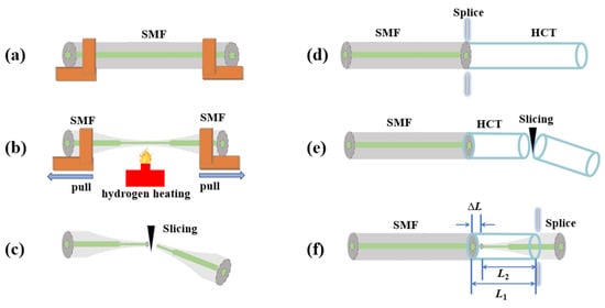
Figure 1.
Schematic illustration of the symmetry-optimized FPI micro-cavity: (a) taper preparation, (b) taper processing, (c) taper fibre cutting, (d) precise fusion splicing of HCT and SMF, (e) Insertion of taper fibre end face into HCT, (f) fusion splicing of HCT and taper fibre.

Table 1.
The key parameter tolerances for the symmetry-optimized FPI micro-cavity.
The critical step enabling the centered waist-inserted assembly is the symmetric cleaving of the tapered fiber section. This process involves precisely cleaving the tapered fiber from both sides simultaneously along planes perpendicular to the fiber axis. This symmetrical removal of material is fundamentally important for two reasons: (1) It ensures the geometric center of the tapered waist region is accurately located relative to the cleaved endfaces. (2) It guarantees that the structural properties are identical on both sides of the waist centerline. This enforced geometric symmetry is essential for achieving the precise alignment required when inserting the waist into the capillary tube to form the FP cavity, and it underpins the sensor’s subsequent balanced response to thermal and mechanical stimuli. These geometric and structural symmetries are directly reflected in key parameters that can be quantitatively evaluated through optical microscopy images at different magnifications. Figure 2a (4× magnification) demonstrates the high symmetry of the tapered fiber, with a measured waist diameter of 69.4 μm. The axial distance from the waist to the 100 μm diameter position is 2.46 mm, indicating uniform taper geometry crucial for balanced force distribution. Figure 2c (40× magnification) confirms that the HCT inner diameter (100 μm) exceeds the fiber waist diameter (69.4 μm), providing symmetric clearance for coaxial insertion and minimizing lateral contact forces. Figure 2b (20× magnification) displays the total length of the HCT. This length equals the cantilever beam length, with L1 = 2.33 mm. The longer effective length enhances the FPI’s strain sensitivity by increasing mechanical deformation under strain. In Figure 2d (40× magnification), the FP cavity’s actual length is 13.98 μm, a key parameter for the interferometric effect. Figure 2d (40× magnification) shows the actual length of the FP cavity, ΔL = 13.98 μm, a critical parameter influencing the interferometric effect.
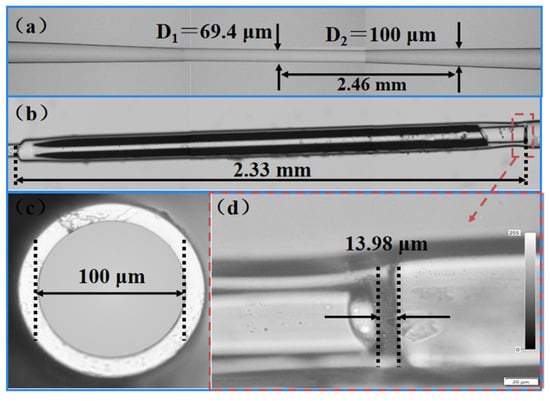
Figure 2.
Pictures of the symmetry-optimized FPI micro-cavity: (a) 4× magnified image demonstrating symmetric tapered fiber geometry, (b) 20× magnified image showing total HCT length, (c) 40× magnified image confirming HCT inner diameter, (d) 40× magnified image revealing FP cavity length.
Figure 3a depicts the operational principle of the symmetry-optimized FPI. The air cavity within the fiber is defined by reflective surfaces M1 and M2. Light with intensity I0 from the supercontinuum source propagates through the fiber, undergoing partial reflection (I1) at M1. The transmitted component reflects at M2 with an intensity of I2, after which both beams recombine in the SMF core to generate interference patterns.
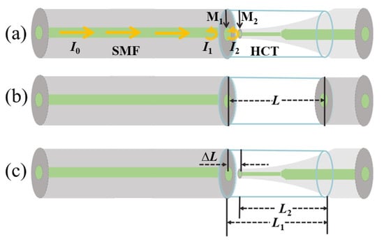
Figure 3.
Sensing principle of the symmetry-optimized FPI micro-cavity: (a) working principle of FPI, (b) interference model of conventional FPI, (c) interference model of symmetry-optimized FPI.
Given the 4% reflectivity at the quartz/air interface, third-order reflections within the FP cavity exhibit merely 0.006% of the incident intensity [26]. Higher-order reflections become energetically negligible, justifying the two-beam interference approximation for FPI analysis. Under this model, the interference spectrum is as follows [32]:
where θ represents the phase shift arising from light propagation within the air cavity. The reflection spectrum follows a cosine distribution due to this two-beam interference. The free spectral range (FSR) of the reflectance spectrum can be formulated as follows [33]:
where m denotes the number of fiber interference orders, λm represents the FPI resonant wavelength associated with the interference order, neff stands for the refractive index of air, and ΔL denotes the actual length of the FP cavity.
As shown in Figure 3b, for the conventional FPI, let the diameter of the micro-cavity in the optical fiber be L. For the abovementioned double-beam FP interference spectrum formed in the micro-cavity structure of the optical fiber, the center wavelength of the m-th-order interference peak is as follows [34]:
Therefore, the sensitivity of the center wavelength shift induced by the tensile force can be approximated as follows [29]:
where A stands for the fiber’s cross-sectional area, and E signifies the Young’s modulus of the fiber material. As illustrated in Figure 3c, the capillary-taper-integrated FPI micro-cavity exhibits m-th-order interference peak wavelength shifts governed by the following [35]:
The strain sensitivity based on the peak wavelength drift of the symmetry-optimized FPI micro-cavity can be expressed as follows [15]:
The variable force sensitivity bears a direct proportionality to the ratio L1/ΔL. Consequently, lengthening the HCT length L1 while minimizing the FP cavity length ΔL provides an effective strategy for enhancing tensile response.
The ultra-high strain sensitivity of the symmetry-optimized FPI micro-cavity stems from two synergistic mechanisms enabled by the design. Firstly, the entire HCT functions as a uniformly elongating cantilever beam under axial stress. Its symmetric, coaxial fixation guarantees pure axial deformation free from bending moments, thereby maximizing the strain transferred to the FP cavity. Secondly, the rigid and symmetric coupling at both ends ensures that the change in the optical path length (ΔL) is precisely equal to the mechanical elongation of the HCT (L1).
When the temperature of the external environment changes, the temperature sensitivity is finally obtained [36]:
where α is the thermal expansion coefficient and κ is the thermo-optical coefficient. It can be seen that the temperature sensitivity of the symmetry-optimized FPI micro-cavity is related to the thermal expansion coefficient of the materials, thermo-optical coefficient, and wavelength of the interference peak.
3. Results and Discussion
Figure 4 depicts spectral and Fast Fourier Transform (FFT) responses of the symmetry-optimized FPI micro-cavity within the 1460–1560 nm wavelength range. According to the inset in Figure 4, λm = 1470.2 nm and λm+1 = 1551.8 nm can be observed at the wavelength of 1510 nm. This indicates the presence of distinct cosinusoidal fringes with an FSR of 81.6 nm, which is very close to that of 81.59 nm calculated by Equation (3). For validation, the FSR spectra are transformed via Fast Fourier Transform (FFT) into spatial frequency spectra. According to the Fourier principles, the resulting frequency response relates inversely to FSR. Figure 4 shows a singular dominant frequency component with a frequency of f = 0.0123 nm−1, confirming that the sensing structure is characterized by two-beam interference. In other words, the reflection spectrum displays the cosine characteristics required for two-beam interference.
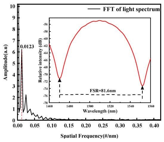
Figure 4.
Spatial frequency spectra of the symmetry-optimized FPI micro-cavity.
The experimental setup for the symmetry-optimized FPI micro-cavity strain measurement is described in Figure 5. A supercontinuum light source (SC, 450–2500 nm) emits light that is routed into the sensing FPI using a 3 dB ring coupler. The light from the sensing FPI then reaches the optical spectrum analyzer (OSA) through the coupler to record the interference spectrum. Upon straightening the sensor FPI, it is affixed to two precise displacement tables, with the distance between the two fixed points being 400 mm. The axial stress variation is regulated by two three-dimensional (3D) moving platforms. In the axial strain test, the right-side moving platform’s micrometer is twisted outward to impose axial strain on the FPI. Regarding the linear change, strain is characterized as the ratio of the variation to the initial quantity. Each rightward rotation of one small division equals applying 25 με to the FPI at a time, which serves to prevent damaging the sensor during stress application.
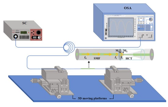
Figure 5.
Schematic diagram of the experimental setup for the axial strain test.
The fixture is designed to stabilize the symmetry-optimized FPI micro-cavity on a 3D moving platform and maintain it in a stretched configuration during the initial phase. The reflectance spectra are obtained within the range of 0 to 125 με by incrementally rotating the knob of the 3D moving platform. The strain characteristics of the sensing FPI are measured by the device shown in Figure 4. Figure 6a shows the variation in the dip in the FPI spectrum with tensile strain. As the strain increases from 0 to 125 με, the dip wavelength in FPI shifts significantly to the right, with a drift of up to 68.0 nm. Figure 6b reveals that the valley wavelength moves notably leftward when the axial strain is reduced from 125 to 0 με, exhibiting a drift as large as 67.9 nm. Notably, a 150 με strain would cause 81.6 nm drift (causing spectral overlap), hence the 125 με limit. Figure 6c exhibits the fitted association between dip wavelength and strain. For forward strain, the FPI sensitivity measures 544.57 pm/με alongside a linearity of 0.9946; in contrast, reverse strain yields a sensitivity of 543.54 pm/με with a linearity of 0.9949. Both sensitivity values demonstrate a superior linear relationship and are closely matched, attesting to the sensor’s excellent reproducibility and reversibility.
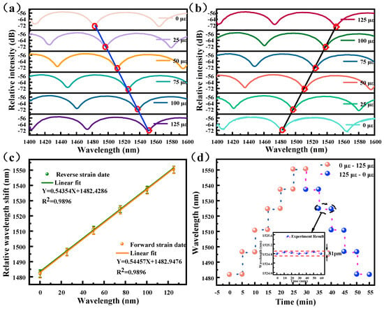
Figure 6.
Strain response and stability of the symmetry-optimized FPI micro-cavity: (a) forward strain test of the symmetry-optimized FPI micro-cavity, (b) reverse strain test of the symmetry-optimized FPI micro-cavity, (c) strain sensitivity of the strain sensor, and (d) stability of the symmetry-optimized FPI micro-cavity.
Stability is a critical factor in practical applications, and stability experiments are conducted on the symmetry-optimized FPI micro-cavity at room temperature. The interference spectrum is logged at each 25 με step, spanning a forward application range of 0–125 με and held for 5 min. The spectrometer’s detection range is reached, resulting in a gradual decrease to 0 με after 125 με strain. Figure 6d demonstrates that stability is validated through consistent reflectance spectral valleys by varying axial stresses. Axial strain is held at 75 με, with sensor reflectance spectra captured every 10 min over 60 min—details are depicted in the inset in Figure 6d. The interference fringes exhibit approximately 0.081 nm fluctuation, primarily due to minor environmental vibrations, indicating good stability. Leveraging the sensitivity of 544.57 pm/με, the system’s minimum detectable strain is approximately 0.149 με under current conditions.
To confirm the superior strain sensing performance of the reference sensor (13.98 μm FP cavity/2.33 mm HCT), we fabricated four sensor groups varying in FP cavity lengths and HCT parameters as supplements. As shown in Figure 7a, the first sensor has an 80.48 μm cavity and a 764.3 μm HCT, with a sensitivity of 18.14 pm/με. The second sensor (Figure 7b) features a 78.14 μm cavity and a 1281.1 μm HCT, achieving 34.66 pm/με. The third (Figure 7c) contains an 82.70 μm cavity and a 634.8 μm HCT, demonstrating 17.5 pm/με, while the fourth (Figure 7d), equipped with a 74.29 μm cavity and a 330.4 μm HCT, shows 5.38 pm/με. All four exhibited lower sensitivity than the reference sensor, validating its superior performance.
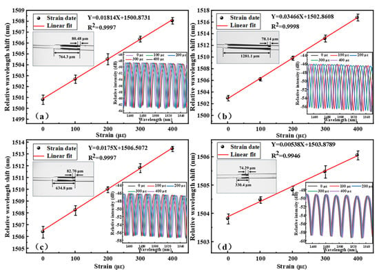
Figure 7.
Strain sensitivity and structural comparison of fiber sensors: (a) sensor with 80.48 μm cavity/764.3 μm HCT, (b) sensor with 78.14 μm cavity/1281.1 μm HCT, (c) sensor with 82.70 μm cavity/634.8 μm HCT, and (d) sensor with 74.29 μm cavity/330.4 μm HCT.
The temperature measurement system for the symmetry-optimized FPI micro-cavity is shown in Figure 8. An SC with a wavelength range of 450–2500 nm is employed in conjunction with an OSA to obtain the reflection spectra. The light reflected from the symmetry-optimized FPI micro-cavity is captured by the OSA with a 3 dB ring coupler to obtain the interference spectrum. In the temperature test experiment of the strain sensor, the sensing component of the FPI fiber is securely affixed to the central stage of a far-infrared rapid-drying oven using high-temperature adhesive tape.
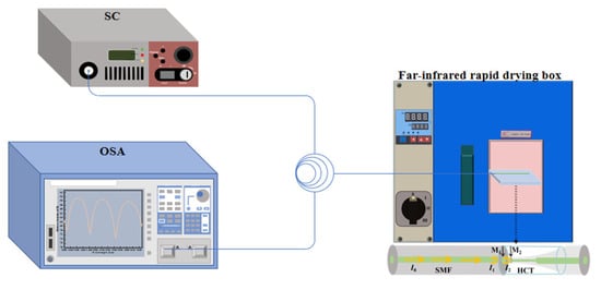
Figure 8.
Schematic diagram of the temperature measurement system.
As shown in Figure 9a, the temperature is incrementally raised from 25 °C to 200 °C in intervals of 25 °C, and the corresponding interference spectra are recorded at each specified temperature. As the temperature increases, the dip wavelength of the symmetry-optimized FPI micro-cavity shows minimal sensitivity to temperature variations due to the relatively small thermo-optical and thermal expansion coefficients of air and quartz fiber, as shown in the inset. Moreover, the reflectance spectra show consistent stability with temperature, suggesting that the sensing properties are not influenced by thermal expansion. Figure 9b presents the linear fit pertaining to temperature. The temperature response is derived from the wavelength shift observed through the trough. The strain sensor shows a temperature sensitivity of 1.02 pm/°C and a cross-sensitivity to temperature of 0.0019 µε/°C. The results reveal that the sensor’s temperature cross-sensitivity is extremely low and negligible, thereby minimizing measurement errors caused by temperature fluctuations.
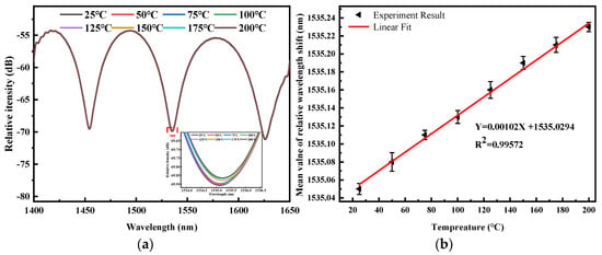
Figure 9.
Temperature response of the symmetry-optimized FPI micro-cavity: (a) reflection spectra of the symmetry-optimized FPI micro-cavity by varying temperatures, and (b) correlation between the mean dip wavelength shift and temperature.
A comparative analysis is performed for our strain sensor in reference to other high-sensitivity strain sensors reported recently. Parameters such as the operational range, strain sensitivity, and temperature sensitivity were compared, and the comparison is presented in Table 2. References [2,36] report negative strain sensitivities (−2.98 nm/με, −23.9 pm/με) due to optical vernier effects inducing blue shifts. Our design avoids vernier principles entirely. Axial strain uniformly elongates both cantilever and cavity in the geometric amplification mechanism, ensuring exclusively positive sensitivity (544.57 pm/με). The results confirm that our sensor has higher strain sensitivity and lower temperature cross-sensitivity. In addition, the production process of the sensor is straightforward without needing costly equipment or hazardous chemicals, boding well for safe and low-cost manufacturing.

Table 2.
Comparative analysis between the symmetry-optimized FPI micro-cavity and previously documented FPI-based sensors.
4. Conclusions
A symmetrically optimized strain sensor, produced through symmetric tapering, cleaving, and FPI assembly with centered waist insertion, is presented. The symmetry inherent in the fabricated structure ensures balanced thermal expansion and uniform strain distribution, directly contributing to this outstanding temperature stability and high-fidelity strain measurement. The strain sensor has excellent properties such as an ultra-high sensitivity (544.57 pm/µɛ), exceptional linearity (99.46%), and ultra-low temperature sensitivity (1.02 pm/°C). For the symmetry-optimized FPI micro-cavity, its temperature cross-sensitivity stands at 0.0019 µε/°C, rendering it less sensitive to temperature variations. Overall, the strain sensor offers notable advantages: high strain sensitivity, low cross-temperature sensitivity, excellent repeatability and stability, alongside a cost-effective and facile manufacturing process. In addition, the sensor, featuring an ultra-high sensitivity, is capable of converting mechanical displacements at the microscale into resolvable wavelength changes. Such a conversion mechanism supports the maintenance of stable interference patterns within the free spectral range, which is fundamental for micro-displacement sensing applications.
Author Contributions
Conceptualization, X.Y. and W.K.; methodology, Y.Z.; software, H.Y.; validation, J.L., C.L. and M.L.; formal analysis, P.K.C.; investigation, Y.Z.; data curation, X.Y.; writing—original draft preparation, X.Y.; writing—review and editing, W.K.; supervision, Y.Z.; project administration, J.L.; funding acquisition, J.L. and P.K.C. All authors have read and agreed to the published version of the manuscript.
Funding
This work was jointly supported by the National Natural Science Foundation of China [42172150], Heilongjiang Provincial Natural Science Foundation of China [JQ2023F001, LH2022F004], Local Universities Reformation and Development Personnel Training Supporting Project from Central Authorities, the Basic Research Support Project for the Excellent Youth Scholars of Heilongjiang Province [YQJH2023077], as well as City University of Hong Kong Donation Research Grants [DON-RMG 9229021 and 9220061].
Data Availability Statement
The experimental results obtained from the study can be acquired from the corresponding author upon request.
Conflicts of Interest
The authors declare no conflicts of interest.
References
- Lashari, G.A. Vernier Effect-Based Strain Sensor with Cascaded Fabry-Perot Interferometers. IEEE Sens. J. 2020, 20, 9196–9201. [Google Scholar]
- Wang, J.; Lu, X.; Mi, C.; Yin, Q.; Lv, J.; Yang, L.; Liu, W.; Yi, Z.; Liu, Q.; Chu, P.K.; et al. Ultra-high sensitivity photonic crystal fiber sensor based on dispersion turning point sensitization of surface plasmonic polariton modes for low RI liquid detection. Opt. Express 2024, 32, 32895–32908. [Google Scholar] [CrossRef]
- Chatterjee, K.; Arumuru, V.; Patil, D.; Jha, R. Multipoint monitoring of amplitude, frequency, and phase of vibrations using concatenated modal interferometers. Sci. Rep. 2022, 12, 3798. [Google Scholar] [CrossRef] [PubMed]
- An, N.; Chen, T.; Zhang, J.; Wang, G.; Yan, M.; Yang, S. Rational electrochemical design of cuprous oxide hierarchical microarchitectures and their derivatives for SERS sensing applications. Small Methods 2024, 8, 2300910. [Google Scholar] [CrossRef]
- Zhao, Y.; Li, B.; Zhong, M.; Fan, H.; Li, Z.; Lyu, S.; Xing, X.; Qin, W. Highly sensitive, wearable piezoresistive methylcellulose/chitosan@ MXene aerogel sensor array for real-time monitoring of physiological signals of pilots. Sci. China Mater. 2025, 68, 542–551. [Google Scholar] [CrossRef]
- Zhang, C.; Dong, Y.; Hu, P.-C.; Fu, H.; Yang, H.; Yang, R.; Dong, Y.K.; Zou, L.; Tan, J. Large-range displacement measurement in narrow space scenarios: Fiber microprobe sensor with subnanometer accuracy. Photonics Res. 2024, 12, 1877–1889. [Google Scholar] [CrossRef]
- Dong, Y.; Li, W.; Zhang, J.; Luo, W.; Fu, H.; Xing, X.; Hu, P.-C.; Dong, Y.K.; Tan, J. High-speed PGC demodulation model and method with subnanometer displacement resolution in a fiber-optic micro-probe laser interferometer. Photonics Res. 2024, 12, 921–931. [Google Scholar] [CrossRef]
- Qi, H.; Jing, X.; Hu, Y.; Wu, P.; Zhang, X.; Li, Y.; Zhao, H.; Ma, Q.; Dong, X.; Mahadevan, C. Electrospun green fluorescent-highly anisotropic conductive Janus-type nanoribbon hydrogel array film for multiple stimulus response sensors. Compos. Part. B Eng. 2025, 288, 111933. [Google Scholar] [CrossRef]
- Gao, X.; Ning, T.; Zhang, C.; Xu, J.; Zheng, J.; Lin, H.; Li, J.; Pei, L.; You, H. A dual-parameter fiber sensor based on few-mode fiber and fiber Bragg grating for strain and temperature sensing. Opt. Commun. 2020, 454, 124441. [Google Scholar] [CrossRef]
- Yang, T.; Qiao, X.; Rong, Q.; Bao, W. Fiber Bragg gratings inscriptions in multimode fiber using 800 nm femtosecond laser for high-temperature strain measurement. Opt. Laser Technol. 2017, 93, 138–142. [Google Scholar] [CrossRef]
- Zheng, Y.; Shum, P.P.; Liu, S.; Li, B.; Auguste, J.-L.; Humbert, G.; Luo, Y. Strain sensitivity enhancement based on periodic deformation in hollow core fiber. Opt. Lett. 2020, 45, 3997–4000. [Google Scholar] [CrossRef]
- Dong, X.; Luo, Z.; Du, H.; Sun, X.; Yin, K.; Duan, J. Highly sensitive strain sensor based on a novel Mach-Zehnder mode inter- ferometer with TCF-PCF-TCF structure. Opt. Lasers Eng. 2019, 116, 26–31. [Google Scholar] [CrossRef]
- Tanaka, S.; Ohtsuka, Y. Fiber-optic strain sensor using a dual Mach-Zehnder interferometric configuration. Opt. Commun. 1991, 81, 267–272. [Google Scholar] [CrossRef]
- Jiao, J.; Chen, J.; Wang, N.; Zhang, J.; Zhu, Y. Study of a fiber optic fabry-perot strain sensor for fuel assembly strain detection. Sensors 2022, 22, 9097. [Google Scholar] [CrossRef] [PubMed]
- Lang, C.; Liu, Y.; Cao, K.; Qu, S. Temperature-insensitive optical fiber strain sensor with ultra-low detection limit based on capillary-taper temperature compensation structure. Opt. Express 2018, 26, 477–487. [Google Scholar] [CrossRef] [PubMed]
- Lin, C.; Wang, Y.; Huang, Y.; Liao, C.; Bai, Z.; Hou, M.; Li, Z.; Wang, Y. Liquid modified photonic crystal fiber for simultaneous temperature and strain measurement. Photonics Res. 2017, 5, 129–133. [Google Scholar] [CrossRef]
- Hou, M.; Wang, Y.; Liu, S.; Li, Z.; Lu, P. Multi-components interferometer based on partially filled dual-core photonic crystal fiber for temperature and strain sensing. IEEE Sens. J. 2016, 16, 6192–6196. [Google Scholar] [CrossRef]
- Xu, Z.; Geng, Y.; Zhu, X.; Lu, J.; Yi, D.; Du, Y.; Wang, J.; Hong, X.; Li, X. Temperature insensitive distributed wide-dynamic-range strain sensing based on polarization-maintaining photonic crystal fiber. J. Phys. D Appl. Phys. 2024, 57, 305103. [Google Scholar] [CrossRef]
- Wei, Y.; Li, L.; Liu, C.; Wang, R.; Zhao, X.; Ran, Z.; Ren, Z.; Jiang, T. High sensitivity fiber cladding SPR strain sensor based on V-groove structure. Opt. Express 2022, 30, 7412–7425. [Google Scholar] [CrossRef]
- Ying, Y.; Wang, J.-K.; Xu, K.; Si, G.-Y. High sensitivity D-shaped optical fiber strain sensor based on surface plasmon resonance. Opt. Commun. 2020, 460, 125147. [Google Scholar] [CrossRef]
- Wang, J.; Liu, W.; Li, Q.; Yang, L.; Lv, J.; Xu, L.; Yin, Q.; Liu, Q.; Chu, P.K.; Liu, C. A high-sensitivity strain sensor based on the core-offset fiber with a micro air bubble. Opt. Commun. 2024, 555, 130235. [Google Scholar] [CrossRef]
- Hu, Y.; Wei, H.; Ma, Z.; Zhang, L.; Pang, F.; Wang, T. Microbubble-based optical fiber Fabry-Perot sensor for simultaneous high-pressure and high-temperature sensing. Opt. Express 2022, 30, 33639–33651. [Google Scholar] [CrossRef]
- Zhang, H.; Jiang, C.; Hu, J.; Song, J.; Zhu, X.; Wang, P.; Li, H. Temperature-insensitive optical fiber strain sensor fabricated by two parallel connection Fabry–Perot interferometers with air-bubbles. Rev. Sci. Instrum. 2023, 94, 045001. [Google Scholar] [CrossRef]
- Favero, F.C.; Araujo, L.; Bouwmans, G.; Finazzi, V.; Villatoro, J.; Pruneri, V. Spheroidal Fabry-Perot microcavities in optical fibers for high-sensitivity sensing. Opt. Express 2012, 20, 7112–7118. [Google Scholar] [CrossRef] [PubMed]
- Liu, S.; Wang, Y.; Liao, C.; Wang, G.; Li, Z.; Wang, Q.; Zhou, J.; Yang, K.; Zhong, X.; Zhao, J.; et al. High-sensitivity strain sensor based on in-fiber improved Fabry-Perot interferometer. Opt. Lett. 2014, 39, 2121–2124. [Google Scholar] [CrossRef] [PubMed]
- Li, Q.; Wang, J.; Mu, H.; Lv, J.; Yang, L.; Shi, Y.; Yi, Z.; Chu, P.K.; Liu, Q.; Liu, C. A Fabry–Pérot interferometer strain sensor composed of a rounded rectangular air cavity with a thin wall for high sensitivity and interference contrast. Opt. Commun. 2023, 527, 128920. [Google Scholar] [CrossRef]
- Liu, Y.; Wang, D.N.; Chen, W.P. Crescent shaped Fabry-Perot fiber cavity for ultra-sensitive strain measurement. Sci. Rep. 2016, 6, 38390. [Google Scholar] [CrossRef]
- Cai, L.; Wang, J.; Chen, M.; Ai, X. A high-sensitivity strain sensor based on an unsymmetrical air-microbubble Fabry-Pérot interferometer with an ultrathin wall. Measurement 2021, 181, 109651. [Google Scholar] [CrossRef]
- Zhao, X.; Zhang, Y.; Zhang, W.; Li, Z.; Kong, L.; Yu, L.; Ge, J.; Yan, T. Ultra-high sensitivity and temperature compensated fabry-perot strain sensor based on tapered FBG. Opt. Laser Technol. 2020, 124, 105997. [Google Scholar] [CrossRef]
- Wang, Z.; Jiang, S.; Yang, P.; Wei, W.; Bao, W.; Peng, B.; Wei, W.; Bao, G. High-sensitivity and high extinction ratio fiber strain sensor with temperature insensitivity by cascaded MZI and FPI. Opt. Express 2023, 31, 7073–7089. [Google Scholar] [CrossRef]
- Pevec, S.; Donlagic, D. All-fiber, long-active-length Fabry-Perot strain sensor. Opt. Express 2011, 19, 15641–15651. [Google Scholar] [CrossRef]
- Lv, J.; Li, W.; Meng, T.; Li, Q.; Wang, J.; Xu, X.; Wang, D.; Liu, W.; Liu, C.; Chu, P.K. Low-temperature cross-sensitivity strain sensor based on a microbubble Fabry-Pérot interferometer with a thin wall. Opt. Fiber Technol. 2023, 80, 103452. [Google Scholar] [CrossRef]
- Liu, C.; Wang, J.; Lv, J.; Song, X.; Liu, W.; Liu, Q.; Li, R.; Li, L.; Yi, Z.; Chu, P.K. Economical and easily implemented Vernier effect bubble microcavity FPI for strain sensing with extreme low-temperature cross-sensitivity. Infrared Phys. Technol. 2025, 150, 105939. [Google Scholar] [CrossRef]
- Sun, C.; Liu, Y.; Li, Y.; Qu, S. Micro-newton strain force and temperature synchronous fiber sensor with a high Q-factor based on the quartz microbubble integrated in the capillary-taper structure. Opt. Express 2022, 30, 8750–8761. [Google Scholar] [CrossRef] [PubMed]
- Liu, Y.; Lang, C.; Wei, X.; Qu, S. Strain force sensor with ultra-high sensitivity based on fiber inline Fabry-Perot micro-cavity plugged by cantilever taper. Opt. Express 2017, 25, 7797–7806. [Google Scholar] [CrossRef] [PubMed]
- Lv, J.; Li, W.; Wang, J.; Lu, X.; Li, Q.; Ren, Y.; Yu, Y.; Liu, Q.; Chu, P.K.; Liu, C. High-sensitivity strain sensor based on an asymmetric tapered air microbubble Fabry-Pérot interferometer with an ultrathin wall. Opt. Express 2024, 32, 19057–19068. [Google Scholar] [CrossRef]
- Wu, Y.; Zhang, Y.; Wu, J.; Yuan, P. Temperature-insensitive fiber optic Fabry-Perot interferometer based on special air cavity for transverse load and strain measurements. Opt. Express 2017, 25, 9443–9448. [Google Scholar] [CrossRef]
- Zhang, P.; Zhang, L.; Wang, Z.; Zhang, X.; Shang, Z. Sapphire derived fiber based Fabry-Perot interferometer with an etched micro air cavity for strain measurement at high temperatures. Opt. Express 2019, 27, 27112–27123. [Google Scholar] [CrossRef]
- Li, L.; Jiang, C.; Hu, C.; Gao, J.; Deng, L.; Cao, T.; Li, H. Highly sensitive strain sensor based on tapered few-mode fiber. Rev. Sci. Instrum. 2023, 94, 075006. [Google Scholar] [CrossRef]
Disclaimer/Publisher’s Note: The statements, opinions and data contained in all publications are solely those of the individual author(s) and contributor(s) and not of MDPI and/or the editor(s). MDPI and/or the editor(s) disclaim responsibility for any injury to people or property resulting from any ideas, methods, instructions or products referred to in the content. |
© 2025 by the authors. Licensee MDPI, Basel, Switzerland. This article is an open access article distributed under the terms and conditions of the Creative Commons Attribution (CC BY) license (https://creativecommons.org/licenses/by/4.0/).