Abstract
This work presents the use of a novel impedance coupling technique and electrical length increase by using stub loading placed from the radiator to the ground plane. This method is applied to the design of a small four-element ultrawideband (UWB) MIMO antenna arranged in axial symmetry to achieve a compact array size while obtaining a bandwidth starting from a very low cutoff frequency compared to a conventional radiator operating at the same frequency. The four-element MIMO antenna, with an operational bandwidth of 1.9 GHz to 30 GHz, is based on a wideband monopole with a semicircular geometry, fed by a coplanar structure and an L-shaped half-ground plane section. To increase the electrical length of the structure and achieve a compact antenna design, reactive stub loading is introduced, placing it on the backside of the substrate, located orthogonally between the radiator and the L-shaped ground plane, obtaining a small-sized configuration. The axial symmetry is employed to increase the antennas’ isolation by taking advantage of the orthogonal positioning and making the radiated fields have a low correlation. The antenna array footprint measures 48 mm × 48 mm, corresponding to 0.3λ0 × 0.3λ0 at the lower cutoff frequency. The array exhibits a low envelope correlation coefficient (ECC) of around 0.033 at 2 GHz, and less than 0.001 at the rest of the bandwidth; a diversity gain (DG) of approximately 10; a stable total active reflection coefficient (TARC) below −10 dB; interport isolation between 20 and 40 dB; and an average gain of 2.8 dBi.
1. Introduction
Driven by the ever-increasing demand for higher data transmission rates, there is a compelling need for devices that can meet these requirements. The use of multiple-input multiple-output (MIMO) antennas and multiple frequency bands has gained significant traction in recent times. However, for personal applications, the demand for small yet highly efficient antennas is paramount. Reducing the size of antenna elements and confining them to small volumes can lead to performance degradation, including reduced bandwidth, minimized radiation efficiency, impedance modifications, and high levels of electromagnetic coupling among elements. This latter issue has severe consequences, as strong electromagnetic field coupling between radiators in an MIMO array degrades the element’s efficiency and gain, and the independence of the elements, resulting in high correlation of their electric fields, consequently restricting channel capacity and transmission rates.
To enhance the transmission rate in personal communication systems, the objective is to maximize the number of antennas integrated into an MIMO configuration. However, realizing this necessitates compact array elements, whose sizes are predominantly constrained by the inherent physical properties of the array and the operating frequency. Hence, a major design challenge for these devices lies in their miniaturization, particularly at lower frequencies. In addition to the requirement for small dimensions, the close proximity of radiators, as noted earlier, inherently limits the device’s performance. Therefore, developing a compact, highly efficient MIMO array with multiple radiators that also maintains low complexity and ease of replication poses a substantial challenge. Consequently, to guarantee a minimally acceptable performance for such applications, a common practice involves comparing the overall antenna dimensions. The objective is to minimize size while simultaneously satisfying key performance metrics. These metrics typically include an envelope correlation coefficient (ECC) less than 0.5, a total active reflection coefficient (TARC) below −10 dB across the full operational bandwidth (which necessitates analysis across various signal phases), and a diversity gain approaching 10.
To meet the aforementioned goals, numerous MIMO antenna proposals have emerged, encompassing medium-, wide-, and ultrawideband frequencies. For instance, Ref. [1] presents a two-port MIMO configuration implemented using circular monopole antennas, operating from 1.4 GHz to 25 GHz. The structure is designed to provide four rejection bands, achieving ECC values below 0.01 and radiation efficiency exceeding 75%. In contrast, Ref. [2] introduces a four-port MIMO antenna design based on a circular semi-hollow structure, achieving a bandwidth of 3.19 GHz to 9.3 GHz, along with an ECC less than 0.02 and TARC below −10 dB from 3 GHz to 9 GHz. The novelty of this design lies in its transparent and flexible implementation. Ref. [3] describes a four-port MIMO array configuration. Each port pair excites a radiator with orthogonal polarizations, operating from 3.15 GHz to 6 GHz. The array exhibits an ECC below 0.002 and element isolation greater than 20 dB. Reference [4] proposes a four-port MIMO array utilizing quasi-circular radiators with a ground plane slot to modify the current path and enhance impedance matching. The array demonstrates a bandwidth from 4.5 GHz to 16.4 GHz, with an ECC less than 0.002 and TARC below −10 dB within the specified bandwidth.
A general trend in antenna array design is the pursuit of compact devices with wide bandwidth and superior electromagnetic performance to meet the demands of high data transmission rates.
This paper expounds the hypothesis that the stub increases the length of the radiator and neutralizes the reactance of the input impedance of the element. To prove it, here is developed a four-element MIMO array utilizing a quasi-circular monopole with modifications to the current path introduced by an open-circuited stub which increases the electric length of the structure, achieving a small-sized configuration for a low cutoff frequency of 1.9 GHz, with decoupling better than 15 dB all over the pass band. The stub adds a path between the radiator and the ground plane, effectively increasing the current trajectory and contributing to the impedance stabilization of the radiator by compensating for the reactive part of the antenna impedance.
2. Case Study: Printed Monopole with Reactive Stub Loading
The bandwidth enhancement of antennas can be achieved through various techniques. For instance, in patch antennas, patch stacking or slot coupling has been demonstrated to improve bandwidth [5,6]. Similarly, external coupling circuits, parasitic couplings [7,8], and modifications to excitation structures [9,10] have also shown effectiveness. This section presents a method for bandwidth enhancement by employing a metallic strip positioned orthogonally to the radiator and the ground plane, called a stub from this point on. This configuration creates a path that increases the current trajectory and compensates for the radiator’s reactive impedance part, improving its coupling over a wider bandwidth, and shifting the lower cutoff frequency to a smaller value by incrementing its electric length.
As an initial case study, a printed monopole with a length of λ/4 at a resonance frequency of 4 GHz is proposed, resulting in a radiator length of approximately 18 mm from the ground plane. The substrate is selected with a dielectric permittivity of 2.2 and thickness of 1.27 mm. The antenna is fed using a coplanar line configuration, as shown in Figure 1a. Using Ansys Electronics Desktop 2019, the simulation results for this structure are presented in Figure 1b.
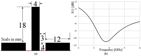
Figure 1.
(a) λ/4 monopole; (b) frequency response.
As observed in Figure 1b, the monopole exhibits a resonance near 4 GHz with port matching around −11 dB. These dimensions are retained, without optimization, when employing the stub-loading technique presented in Figure 2a. The geometrical modification involves altering the shape of one of the ground planes into an L-shaped geometry and aligning it parallel to the radiator. The structure line in the form of a stub is positioned on the backside of the substrate, orthogonally between the L-shaped ground plane and the radiator. Figure 2b illustrates the frequency response of the antenna with the stub loading. It is observed that the radiator input impedance matching is improved, the lower cutoff frequency is decreased, and the bandwidth is also widened. The radiator characteristics are highly dependent on the position of the stub. As seen in Figure 2b, both the bandwidth and the lower cutoff frequency are influenced by the distance between the stub and the ground plane. The best performance is achieved with a stub-to-ground plane distance of 14 mm, resulting in a −10 dB bandwidth from 1.72 GHz to 3.94 GHz, thus enhancing the antenna’s performance, which ensures the hypothesis is correct, in this aspect.
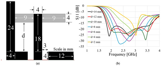
Figure 2.
(a) Monopole with stub loading; (b) frequency response for different d values.
The stub’s placement stabilizes the antenna’s impedance considering the −10 dB bandwidth previously pointed out, as illustrated in Figure 3. In this case, Figure 3 shows the comparison of the magnitude and the real and imaginary parts of the impedance of the monopole with and without the stub structure when the stub is located 14 mm from the ground plane. The comparison reveals that these parameters, when the stub is used, present more stability. It is noteworthy that in the case of the reactance, the values are more stable, since this is closer to 0 Ω from 1.72 GHz to 3.94 GHz. The importance of reducing the imaginary (reactive) component of an antenna’s impedance is paramount for several reasons. Primarily, it directly impacts the maximization of radiation efficiency. A significant reactive impedance can lead to energy being stored in the antenna’s near-field (as electric and magnetic fields), which is then reflected back to the source. This not only compromises the integrity of the transmitting device but also means this stored energy is not radiated, thus reducing effective power output.
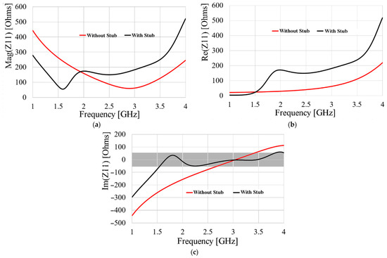
Figure 3.
Impedance behavior of the loaded antenna: (a) magnitude; (b) real part; (c) imaginary part.
Furthermore, a substantial reactive component makes the antenna’s impedance highly frequency-dependent, which can severely limit the radiator’s operational bandwidth. In this specific case, achieving a wide bandwidth is simplified through the precise tuning of a stub; the optimization process is shown in Appendix A. As is depicted in the flow chart, this method solely requires accurate positioning of the stub relative to the radiator and the ground plane, offering a significant advantage over other bandwidth-enhancing techniques. These alternative methods, such as [11,12], often involve more complex implementation procedures.
3. UWB Antenna Design and Simulated Results
Having observed the expected interaction behavior of the stub from the radiator to the ground plane and obtained an enhanced bandwidth performance, a wideband antenna design is proposed to meet the requirements of various bands. The design starts with a circular monopole, modifying its geometry to leave only half, and implementing coplanar feeding to apply the stub-loading technique. The initial UWB structure is intentionally left unoptimized to demonstrate that the proposed technique, with its simplicity, also helps improve the coupling and bandwidth of a given antenna, without the need to introduce other more complex methods, as used by some configurations published in the literature, which will be mentioned later in a comparative table. Figure 4a presents the initial unoptimized configuration of the semicircular monopole, while Figure 4b shows the variant with the proposed stub, the latter having a total footprint of 28 mm × 17.5 mm. The stub length is set for the best port matching, obtaining 16 mm after a parametric simulation process.
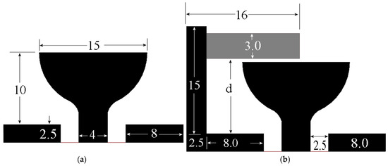
Figure 4.
Proposed UWB antenna, scale in mm: (a) without stub loading; (b) with stub loading.
Figure 5 presents the simulated reflection coefficient (S11) results for both configurations. Figure 5a illustrates the frequency response behavior of the configuration without the stub, while Figure 5b depicts the antenna behavior with the proposed method, using the stub-to-ground plane separation as parameter.
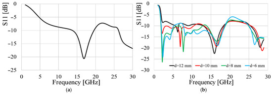
Figure 5.
Frequency response of semi-disk monopole: (a) without stub loading; (b) with stub loading.
While the unoptimized antenna without stub loading exhibits a port matching from 13.7 GHz to 19.5 GHz, as shown in Figure 5a, by modifying the ground plane to an L-shape and introducing the stub for tuning, it enhances the antenna’s bandwidth without further geometry optimization, as depicted in Figure 5b. A separation distance, d, of 8 mm between the stub and the ground plane yields an impressive bandwidth spanning from 1.9 GHz to 12.79 GHz. To further enhance the bandwidth of the proposed antenna, Kraus’s technique was employed on the ground plane (GND) [13]. While Kraus does not explicitly detail the modification of discontinuities, he emphasizes the need for smooth transitions in antenna geometry. This design principle is crucial for achieving a uniform current distribution, which, in turn, is key to stabilizing impedance over a wider bandwidth. Following this approach, the aim is to create a smooth transition in the current distribution on the ground plane closest to the radiator and its feed line. The curvature of the ground plane is obtained by a parametric analysis made in Ansys Electronics. The final configuration is depicted in Figure 6a, with the same dimensions as given in Figure 4b, with d = 8 mm, and its frequency response is given in Figure 6b.
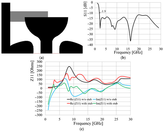
Figure 6.
(a) Stub-loaded antenna with Kraus technique; (b) frequency response; (c) comparison of input impedance of antenna with and without stub.
As observed in Figure 6b, the antenna’s frequency response is enhanced by employing Kraus’s technique, resulting in improved coupling in the mid and high bands compared to Figure 5b. The curvature of the ground plane was obtained by a parametric study made with Ansys Electronics. This leads to a remarkably wide bandwidth spanning from 1.98 GHz to 30 GHz, as demonstrated in Figure 6b. Figure 6c shows how the real part of the input impedance is kept between 50 Ω and 150 Ω when the stub is introduced compared to the conventional monopole, where this parameter changes from 50 Ω to 250 Ω. Moreover, the imaginary part is sustained between −50 Ω and 50 Ω, when the stub is used, and from −100 Ω to 120 Ω when it is not employed.
As previously shown, employing the stub as a tuning network not only controls the reactive component of the radiator’s impedance but also increases the current path, effectively augmenting its electrical length. Consequently, the lower cutoff frequency of the antenna’s bandwidth is significantly reduced, enabling the realization of a compact radiator operating at very low frequencies. The phenomenon of current path enlargement can be observed in Figure 7, which illustrates how the surface current distribution is fed back to the GND at different frequencies.

Figure 7.
Surface current distribution at (a) 2 GHz; (b) 5 GHz); (c) 15 GHz; (d) 20 GHz.
4. MIMO Configuration and Simulated Metrics
Leveraging the antenna’s compact size of 28 × 17.5 mm2, which is relatively small compared to other references that are discussed later but shows the lowest cutoff frequencies, a four-element MIMO array is implemented. The proposed geometry exhibits axial symmetry to exploit the orthogonal placement of the radiators and takes advantage of the surface current distribution shown in Figure 7, allowing for the generation of a low correlation between their electric fields, thereby enhancing performance. The proposed geometry is illustrated in Figure 8. The array footprint is 48 × 48 mm2.
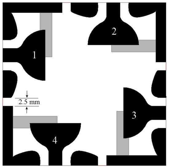
Figure 8.
Proposed four-port MIMO UWB antenna array.
Owing to the axial symmetry of the antenna array, it is sufficient to present the results for the S11, S12, and S13 parameters only, as other combinations of subscripts yield similar results [14,15]. The simulated results of the S-parameters are depicted in Figure 9. As observed in these results, the array maintains a frequency response ranging from 1.9 GHz to 30 GHz. Additionally, the element isolation within the array exhibits values between 20 and 40 dB. These latter outcomes are noteworthy as the configuration achieves high isolation values compared to other proposals in the literature without introducing additional isolation techniques beyond the orthogonal arrangement of elements.
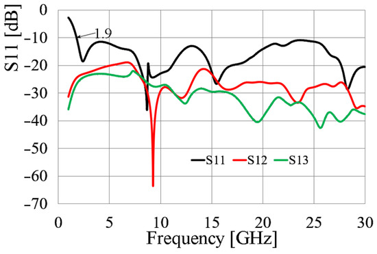
Figure 9.
Simulated S-parameters of the MIMO antenna array.
To verify the performance of the array for MIMO applications, various metrics are employed to evaluate its behavior. Among the most used metrics is the envelope correlation coefficient (ECC), which calculates the correlation of the radiated electric fields by a pair of antennas. The mathematical expression for the ECC in terms of S-parameters is given by (1a), while (1b) presents the ECC in terms of the far-field electric fields.
where is a complex vector function that describes the kth 3D radiation pattern at the Fraunhofer zone, is the Hermitian product, and is the solid angle differential.
Calculating the ECC using (1b) is a tedious and computationally intensive process. Furthermore, for practical and measurement purposes, it necessitates sophisticated measurement equipment to determine the magnitudes of far-field components around the device under test, for all values of , making it challenging and costly to implement. However, for antennas exhibiting a radiation efficiency greater than 90% (achieved in this work), the results obtained using (1a) are valid and converge with those derived from the electric field method [16,17,18]. Consequently, for this work, Equation (1a) will be employed to obtain the ECC in both the simulation and measurement processes.
Another metric is the diversity gain (DG). DG is a measure of the enhanced performance achieved by employing a spatially diverse antenna system compared to a single-antenna system. Spatial diversity is realized by utilizing multiple physically separated antennas to receive the same signal. It represents the reduction in transmission power required to attain a specific performance level, such as a particular bit error rate, compared to a single-antenna system. The mathematical expression for DG is given in (2).
Finally, the total active reflection coefficient (TARC) is a metric that quantifies the reflected signal relative to the received signal in an antenna array. As its name suggests, it is a reflection coefficient, but in this case, it provides information about this phenomenon for an entire antenna array. TARC indicates the amount of energy accepted by the system as a whole and determines the amount of reflected energy, thereby providing information about the system’s bandwidth. TARC is calculated using (3).
where is the number of elements of the array. Developing expression (3) for N = 4, the TARC is described in (4).
As evident in (4), the TARC not only provides the ratio of reflected voltage to incident voltage for the overall array but also considers the different phases with which the signals can arrive along different paths. This metric, therefore, provides valuable information about the performance of the MIMO array, offering a more realistic estimation of what occurs in a multipath-rich environment.
Using (1), (2), and (4), the results were calculated, and the graphics are presented in Figure 10. In the case of the TARC, as seen in (4), three different phases must be employed: since these phases are random values in [0°, 360°), the analysis was simplified, choosing different values for , and setting .
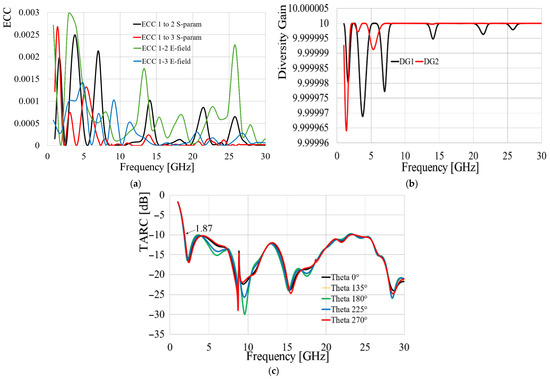
Figure 10.
Simulated MIMO metrics: (a) ECC; (b) DG; (c) TARC.
As observed in Figure 10a, the envelope correlation coefficient (ECC) between antennas 1 and 2, and between antennas 1 and 3, indicates a very low field correlation with maximum values below 0.003 for both cases. This confirms negligible interference between the electric fields of the antennas. In Figure 10b, the low ECC values result in high diversity gain (DG), indicating that the employed diversity technique achieves near-optimal performance across the entire range of interest. Furthermore, the total active reflection coefficient (TARC) analysis, as specified, demonstrates convergent behavior in the obtained curves when using different values for the first phase, ensuring a system bandwidth ranging from 1.87 GHz to 30 GHz, while the cross-polarization is around 10 to 15 dB below the co-polarization levels.
Finally, Figure 11 illustrates the simulated gain patterns at various frequencies. As examined in this figure, the antenna exhibits a quasi-omnidirectional gain pattern in the H-plane with an average value of 2.8 dBi. In the E-plane, the pattern exhibits small nulls at different angles.
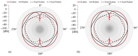
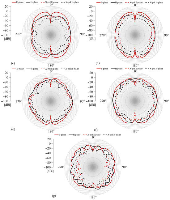
Figure 11.
Simulated gain pattern: (a) 2 GHz; (b) 5 GHz; (c) 10 GHz; (d) 15 GHz; (e) 20 GHz; (f) 25 GHz; (g) 30 GHz.
5. Prototype and Measured Results
The prototype of the ultrawideband MIMO array is shown in Figure 12. Following the same considerations as in the simulation process due to the axial symmetry, the presented measured results are limited to the relationship between antenna 1 and antennas 2 and 3, as any other combination would simply be a mirror image of these outcomes.
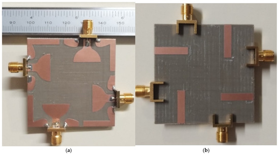
Figure 12.
Photography of the MIMO array prototype: (a) top layer; (b) bottom layer.
Figure 13 shows the measured results of the S-parameters, the ECC, the DG, and the TARC. These results were obtained in a shielded cell cover by electromagnetic absorbers and a Vector Network Analyzer N5244A from Agilent.
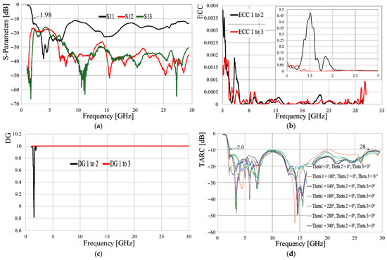
Figure 13.
Measured results: (a) S-parameters; (b) ECC; (c) DG; (d) TARC.
Regarding the frequency response displayed in Figure 13a, the antenna has a bandwidth from, approximately, 2 GHz to 30 GHz, while the isolation among the elements of the array ranges from 18 dB at low frequencies to values higher than 30 dB in the high band.
The ECC behavior is depicted in Figure 13b. In this case, an image in the picture was added to appreciate the behavior of this metric in the range of 1 GHz to 3 GHz, while on the main scale, the ECC curves are recorded from 3 GHz to 30 GHz. This separation of intervals was performed since the maximum value of the ECC is observed between 1 GHz and 3 GHz, obtaining the maximum at 1.5 GHz, although these values are not of interest since they are outside the bandwidth. From 2 GHz to 3 GHz, the ECC values are less than 0.05, while for the rest of the bandwidth, the values are smaller than 0.0005. These results ensure that the correlation between the electric fields of the different antennas in the array is relatively negligible. On the other hand, as a result of a very low ECC, the diversity gain has values close to the optimum within the bandwidth of interest, as shown in Figure 13c. Regarding the TARC, similar considerations were taken to those of the previous section, where the values of and = 0° are proposed, while different values for are considered. As a result of this analysis, Figure 13d shows a convergence in the reflection coefficient curves, presenting a system bandwidth that goes from 2 GHz to frequencies around 28 GHz, having at this frequency slight decoupling of −9.9 dB for the combination when = 100°. Even so, the results related to the TARC are outstanding, preserving the system’s bandwidth.
Ultrawideband antennas are highly desirable options for pulse burst communications. For this type of transmission, low dispersion is crucial, and therefore, the group delay for these applications must be very low. Accordingly, Figure 14 presents a comparison of the simulated and measured group delay results.
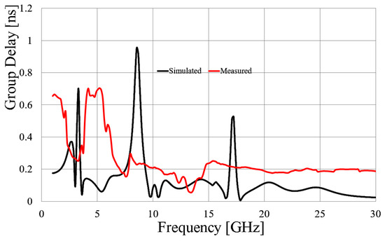
Figure 14.
Comparison of simulated and measured group delay.
As observed in Figure 14, the maximum group delay values do not exceed the 1 ns limit, with an average measured value of approximately 0.2 ns, ensuring very low signal dispersion.
Figure 15 displays the normalized gain patterns. Due to equipment limitations, the patterns were limited to 2 GHz, 5 GHz, 10 GHz, 15 GHz, and the cross-polarization at 2 GHz. As observed in Figure 15, the gain pattern exhibits a quasi-omnidirectional behavior in the H-plane, while in the E-plane, it presents multiple nulls at different angles and frequencies. To avoid cluttering the graphs in Figure 15, cross-polarization representation was limited to the measurement at 2 GHz. However, the behavior of x-pol is measured across different frequencies, with values of at least 35 to 40 dB relative to co-polarization. On the other hand, Figure 16 presents the average peak gain for different frequencies, and as displayed, the peak gain goes from 1.1 to 3.5 dBi.
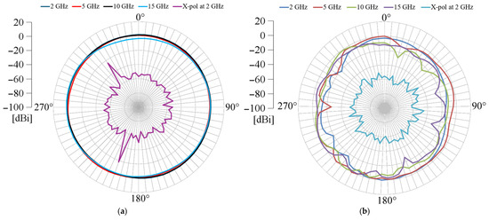
Figure 15.
Measured gain pattern: (a) H-plane; (b) E-plane.
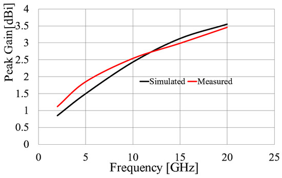
Figure 16.
Comparison of simulated and measured peak gain for different frequencies.
The antenna gains and gain patterns were measured inside an anechoic chamber, with a reference UWB horn antenna, able to work from 1 GHz to 20 GHz. The measurement setup is presented in Figure 17.

Figure 17.
Gain pattern measurement setup: (a) front view; (b) back view.
Finally, Table 1 provides a comparison of different state-of-the-art publications regarding UWB four-port MIMO antennas and compares their size according to the free-space wavelength, λ0, at their corresponding lower cutoff frequency.

Table 1.
Comparison of state-of-the-art publications regarding four-port UWB MIMO antennas.
The asterisks in Table 1 represent the following: * The complexity column is a subjective parameter based on the authors’ personal assessment of the radiator geometry and the various design techniques employed. For instance, the geometry used in reference [21], based on the SARS-CoV-2 virus, is deemed difficult to replicate and has numerous variables that must be fine-tuned and optimized for proper antenna performance. In contrast, reference [20] presents radiators with regular geometric compositions, simplifying their design. Consequently, the proposed antenna in this work is considered to have low complexity due to its geometry based on regular and easily replicable shapes.
** Reference [4], while presenting a TARC response, offers an incomplete analysis, failing to present the results as a function of the different phases involved in the process [23].
*** Reference [20] similarly provides an incomplete TARC analysis for the same reasons as reference [4]. Additionally, since TARC represents the ratio of reflected energy to incident energy in the array, it exhibits values far exceeding −10 dB. Moreover, for frequencies near 2 GHz, the value of this metric is above 0 dB, indicating that the antenna emits energy at these frequencies without a source at its ports, which is physically impossible.
In conclusion, the proposed work is competitive with those recently published in the literature, demonstrating superior bandwidth, excellent diversity gain, very good TARC performance, and high isolation, while employing easily replicable techniques.
6. Discussions
The open-circuited stub technique clearly demonstrated its utility in enhancing two crucial antenna design parameters: (a) stabilizing the radiator’s port impedance over a wider bandwidth, thereby achieving ultrawideband operation, and (b) increasing the electrical length of the radiator, which allows for significantly lower cutoff frequencies compared to a similarly sized radiator without the stub.
The simplicity of this technique ensures repeatable and easily replicable results, making it applicable to nearly any planarized monopole radiator geometry, whether excited by a microstrip line or, as in this case, by coplanar feeding. The technique showed that it is only necessary to optimize the stub’s performance, primarily by adjusting its separation from the radiator, without needing to modify the radiator’s geometry itself. This keeps the design complexity considerably low, unlike other designs found in the literature, such as those in [13,14], which require the optimization of numerous parameters.
Furthermore, employing an axially symmetric topology is an excellent option for enhancing the overall performance of an MIMO array. This approach significantly reduces mutual coupling levels between radiators, thereby improving performance in multipath environments. With these results in miniaturization and performance, including ultrawideband operation, this type of array is well suited for sub-6 GHz radio communication applications, such as the 2.4 GHz ISM band, 3.5 GHz for 5G, and millimeter-wave applications at 26 GHz to 28 GHz for fifth- and sixth-generation telephony.
7. Conclusions
This research presents the design of an ultrawideband antenna for four-port MIMO applications. The design utilizes a stub-loading technique placed orthogonally between the radiator and an L-shaped ground plane segment. This technique enables compensation for changes in the radiator’s reactive component over a broader frequency range, resulting in a more stable antenna impedance across a wider bandwidth. Additionally, the same technique facilitates a trajectory between the radiator and the ground plane, causing the surface current path to be significantly longer, leading to a larger electrical length and, consequently, a lower cutoff frequency at much lower values with a very small radiator size. Furthermore, the antenna exhibits MIMO metrics comparable to those reported in the literature while employing a simpler and more replicable structure. Moreover, it achieves isolation levels among elements ranging from 20 to 40 dB without the need for additional isolation techniques beyond the orthogonal placement of radiators.
Author Contributions
Conceptualization, J.A.T.-M. and H.J.-A.; methodology, J.A.T.-M. and R.L.-M.; software, R.F.-L., R.G.-V. and A.P.-M.; validation, J.A.T.-M., H.J.-A., A.V.-T. and R.F.-L.; formal analysis, J.A.T.-M., A.V.-T., A.P.-M. and R.G.-V.; investigation, J.A.T.-M., H.J.-A., R.L.-M. and R.F.-L.; resources, J.A.T.-M., R.L.-M. and A.V.-T.; data curation, A.V.-T., R.G.-V. and A.P.-M.; writing—original draft preparation, J.A.T.-M., writing—review and editing, H.J.-A., R.L.-M., A.V.-T. and R.F.-L.; visualization, A.P.-M. and R.G.-V.; supervision, H.J.-A. and A.V.-T.; project administration, J.A.T.-M. and R.L.-M.; funding acquisition, J.A.T.-M., H.J.-A. and A.V.-T. All authors have read and agreed to the published version of the manuscript.
Funding
This research was funded by Instituto Politécnico Nacional, grant number 20250817.
Data Availability Statement
All data are provided in the article.
Conflicts of Interest
The authors declare no conflicts of interest.
Abbreviations
The following abbreviations are used in this manuscript:
| ECC | Envelope Correlation Coefficient |
| TARC | Total Active Reflection Coefficient |
| DG | Diversity Gain |
| MIMO | Multiple-Input/Multiple-Output |
Appendix A
The design process begins with the proposal of a monopole antenna featuring a selected geometry. This antenna can be excited via either a microstrip line or a coplanar waveguide. The proposed methodology is valid and applicable for both excitation options.
The first arm of the stub is then introduced, connected to one end of the ground plane. This arm is designed with a length (lb) approximately 50% greater than the radiator’s length, allowing for parameterization to achieve an acceptable result. This result is expected to show an improved coupling of the radiator. The width of this arm is designed to be equal to or close to the ground plane’s width, enabling it to function as an extension of the ground plane. Both the width and length of this arm are parameterized until an improvement in the radiator’s coupling (and potentially bandwidth) is achieved.
Next, the second arm of the stub is proposed. One end of this arm is connected to the first arm, while the other end remains open-circuited. Its length is designed such that its open end extends beyond the radiator’s symmetry axis. The width of this second arm is proposed to be thinner than that of the first arm. This design choice aims to increase the inductive effect, thereby more efficiently enhancing both self-coupling and enlarging the electrical length. From these initial dimensions, the position of the second arm relative to the ground plane, as detailed in the article, as well as its length, are parameterized to achieve the best possible performance or the desired characteristic for the designer, as described in Figure A1.
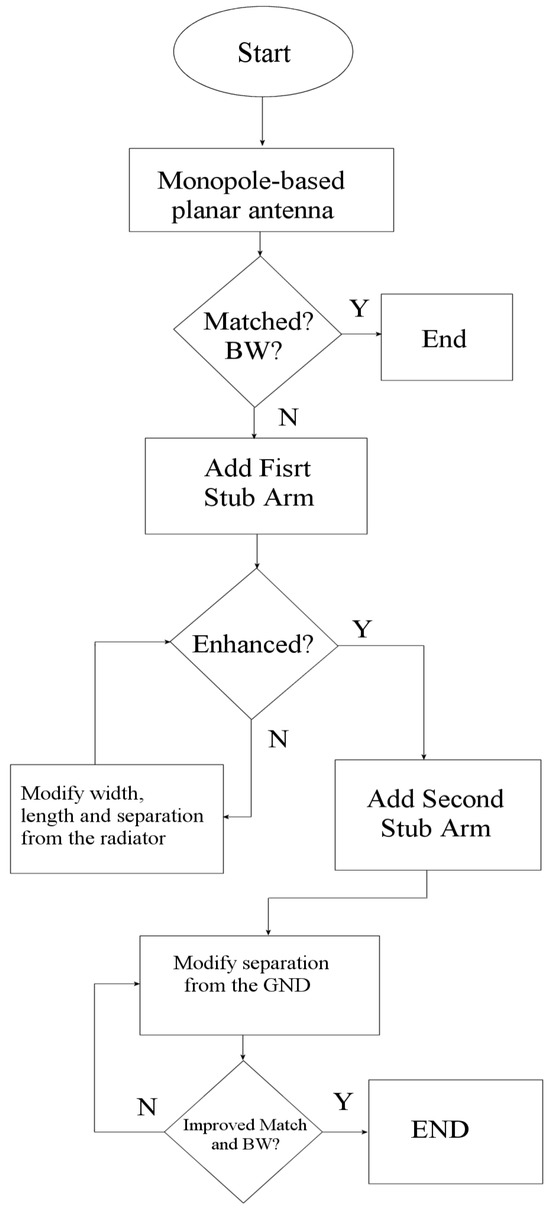
Figure A1.
Flowchart.
References
- Zhao, L.; Wang, Y.; Liu, C.; Song, D.; Hu, C.; Li, C.; Zhao, H.; Wang, Z. Compact Circular-Shaped MIMO Antenna Covers UWB Bandwidth With Four Frequently-Used Band-Notched Characteristics for Multi-Scenario Applications. IEEE Access 2024, 12, 32762–32771. [Google Scholar] [CrossRef]
- Desai, A.; Hsu, H.-T.; Yousef, B.M.; Ameen, A.M.; Tsao, Y.-F.; Ibrahim, A.A. UWB Connected Ground Transparent 4-Port Flexible MIMO Antenna for IoT Applications. IEEE Internet Things J. 2024, 11, 12475–12484. [Google Scholar] [CrossRef]
- Naser, H.M.; Al-Ani, O.A.; Mosleh, M.F. W-Shaped Eight-Port Wideband MIMO Antenna. Progress. Electromagn. Res. C 2023, 134, 211–222. [Google Scholar] [CrossRef]
- Kumar, P.; Pathan, S.; Vincent, S.; Kumar, O.P.; Yashwanth, N.; Kumar, P.; Shetty, P.R.; Ali, T. A Compact Quad-Port UWB MIMO Antenna With Improved Isolation Using a Novel Mesh-Like Decoupling Structure and Unique DGS. IEEE Trans. Circuits Syst. II Express Briefs 2023, 70, 949–953. [Google Scholar] [CrossRef]
- Croq, F.; Pozar, D.M. Millimeter-Wave Design of Wide-Band Aperture-Coupled Stacked Microstrip Antennas. IEEE Trans. Antennas Propag. 1991, 39, 1770–1776. [Google Scholar] [CrossRef]
- Lee, R.Q.; Lee, K.-F. Experimental Study of the Two-Layer Electromagnetically Coupled Rectangular Patch Antenna. IEEE Trans. Antennas Propag. 1990, 38, 1298–1302. [Google Scholar] [CrossRef]
- Pues, H.F.; Van de Capelle, A.R. An Impedance-Matching Technique for Increasing the Bandwidth of Microstrip Antennas. IEEE Trans. Antennas Propag. 1989, 37, 1345–1354. [Google Scholar] [CrossRef]
- Schaubert, D.H. Some Conformal, Printed Circuit Antenna Designs. In Proceedings of the Workshop on Printed Circuit Antenna Technology, Las Cruces, NM, USA, 17–19 October 1979. [Google Scholar]
- Luk, K.M.; Mak, C.L.; Chow, Y.L.; Lee, K.F. Broadband Microstrip Patch Antenna. Electron. Lett. 1998, 34, 1442–1443. [Google Scholar] [CrossRef]
- Mak, C.L.; Luk, K.M.; Lee, K.F.; Chow, Y.L. Experimental Study of a Microstrip Patch Antenna with an L-Shaped Probe. IEEE Trans. Antennas Propag. 2000, 48, 777–783. [Google Scholar] [CrossRef]
- Zhang, J.-E.; Yang, W.-W.; Chen, J.-X. Hyper-High-Order Modes Dielectric Resonator Antenna and Array with Extended Bandwidth and Stable High Gain. IEEE Trans. Antennas Propag. 2025, 1. [Google Scholar] [CrossRef]
- Hussain, M.; Sufian, M.A.; Alzaidi, M.S.; Naqvi, S.I.; Hussain, N.; Elkamchouchi, D.H.; Sree, M.F.A.; Fatah, S.Y.A. Bandwidth and Gain Enhancement of a CPW Antenna Using Frequency Selective Surface for UWB Applications. Micromachines 2023, 14, 591. [Google Scholar] [CrossRef]
- Kraus, J.D. The Helical Antenna. Proc. IRE 1949, 37, 263–272. [Google Scholar] [CrossRef]
- Khandekar, R.; Sipal, D. Design and Analysis of Mm-Wave MIMO Antenna With a UWB AMC. IEEE Antennas Wirel. Propag. Lett. 2025, 1–5. [Google Scholar] [CrossRef]
- Chaturvedi, D.; Lanka, T.; Kumar, A. Compact 4-Port MIMO Antenna-Diplexer Utilizing Slotted-HMSIW Technology. IEEE Lat. Am. Trans. 2025, 23, 628–635. [Google Scholar] [CrossRef]
- Hallbjorner, P. The Significance of Radiation Efficiencies When Using S-Parameters to Calculate the Received Signal Correlation from Two Antennas. IEEE Antennas Wirel. Propag. Lett. 2005, 4, 97–99. [Google Scholar] [CrossRef]
- Blanch, S.; Romeu, J.; Corbella, I. Exact Representation of Antenna System Diversity Performance from Input Parameter Description. Electron. Lett. 2003, 39, 705–707. [Google Scholar] [CrossRef]
- Sharawi, M.S.; Hassan, A.T.; Khan, M.U. Correlation Coefficient Calculations for MIMO Antenna Systems: A Comparative Study. Int. J. Microw. Wirel. Technol. 2017, 9, 1991–2004. [Google Scholar] [CrossRef]
- Pandya, K.; Upadhyaya, T.; Patel, U.; Sorathiya, V.; Pandya, A.; Al-Gburi, A.J.A.; Ismail, M.M. Performance Analysis of Quad-Port UWB MIMO Antenna System for Sub-6 GHz 5G, WLAN and X Band Communications. Results Eng. 2024, 22, 102318. [Google Scholar] [CrossRef]
- Jayant, S.; Srivastava, G.; Kumar, S. Quad-Port UWB MIMO Footwear Antenna for Wearable Applications. IEEE Trans. Antennas Propag. 2022, 70, 7905–7913. [Google Scholar] [CrossRef]
- Elsharkawy, R.R.; El-Hameed, A.S.A.; El-Nady, S.M. Quad-Port MIMO Filtenna With High Isolation Employing BPF With High Out-of-Band Rejection. IEEE Access 2022, 10, 3814–3824. [Google Scholar] [CrossRef]
- Abd El-Hameed, A.S.; Wahab, M.G.; Elshafey, N.A.; Elpeltagy, M.S. Quad-Port UWB MIMO Antenna Based on LPF with Vast Rejection Band. AEU—Int. J. Electron. Commun. 2021, 134, 153712. [Google Scholar] [CrossRef]
- Fritz-Andrade, E.; Jardon-Aguilar, H.; Tirado-Mendez, J.A. The Correct Application of Total Active Reflection Coefficient to Evaluate MIMO Antenna Systems and Its Generalization to N Ports. Int. J. RF Microw. Comput.-Aided Eng. 2020, 30, e22113. [Google Scholar] [CrossRef]
Disclaimer/Publisher’s Note: The statements, opinions and data contained in all publications are solely those of the individual author(s) and contributor(s) and not of MDPI and/or the editor(s). MDPI and/or the editor(s) disclaim responsibility for any injury to people or property resulting from any ideas, methods, instructions or products referred to in the content. |
© 2025 by the authors. Licensee MDPI, Basel, Switzerland. This article is an open access article distributed under the terms and conditions of the Creative Commons Attribution (CC BY) license (https://creativecommons.org/licenses/by/4.0/).