Abstract
A skid-to-turn (STT) missile is an axisymmetric structure missile, and its control system consists of a pitch channel and a yaw channel with an axisymmetric structure. To achieve the fast response of the STT missile system, a compound control method of aerodynamic force and lateral thrust based on regional pole assignment (RPA) is proposed. In the aerodynamic control system, the linear quadratic regulator (LQR) is used to design the controller, and the sliding mode control method is used to design the controller of the lateral thrust system. The regional pole assignment is introduced into the aerodynamic system to improve the compound control system response speed. The problems of regional pole assignment and system stability are solved by a linear matrix inequality (LMI). Considering that the missile flies at different altitudes, the missile system is controlled by gain scheduling. Compared to previous designs of time-varying compound control systems for STT missiles or hypersonic vehicles, in order to meet the practical requirement of a fast response for the vehicle, this time-varying compound control strategy can achieve faster tracking response and attitude control for the STT missile. Finally, through simulations of the pitch channel and yaw channel control systems of the STT missile, the effectiveness of the designed compound control system in achieving a fast response is verified.
1. Introduction
Hypersonic missiles are more than 5 times the speed of sound flight of missiles, have the advantages of fast response speeds and penetration abilities, and are important combat aircraft in the field of aviation [1]. Typical missiles are the Russian “Zircon” missile, the United States “Dark Eagle” missile, and the Chinese “DF-17” missile [2,3,4]. It can be divided into skid-to-turn (STT) missiles and bank-to-turn (BTT) missiles according to different turning modes in the course of flight [5,6]. The BTT missile is a non-axisymmetric aircraft. However, an STT missile is an axisymmetric aircraft with a fast response speed and a relatively simple system structure. The pitch channel, yaw channel, and roll channel of the STT missile can be designed separately [7,8,9]. With the rapid development of aircraft in the field of aviation, it is particularly important to design a fast response control system for the STT missile to further improve the response speed.
In the study of hypersonic missile control system design, many researchers only consider the control scheme of the aerodynamic system and do not consider the constraint when the aerodynamic rudder of the vehicle reaches saturation [10,11,12,13,14]. When the aerodynamic rudder is saturated, the control force and torque cannot be generated continuously, which makes the system unstable and then malfunction [15,16]. To make the missile control system stable, it is very important to add the lateral thrust provided by the engine to the system so that the missile control system can continue to work stably. There are many studies on compound control methods. Reference [17] applies neural networks and sliding mode control to robotic systems. In [18], neural network and proportional integral derivative (PID) controls are used to design the controller of the electromagnetic linear simulator. References [19,20] apply neural networks, adaptive control, and integral sliding modes to inertially stabilized platform systems. However, the research object of the above compound control method is not a hypersonic vehicle. To design the compound control system of a hypersonic missile, a compound control method based on linear quadratic regulator (LQR) and sliding mode control is proposed in this paper. At the same time, in order to achieve the fast response of the system, the regional pole assignment (RPA) is applied to the aerodynamic system to improve the response speed of the system.
The control methods used to improve the system response speed include the PID control method, adaptive control method, pulse control method, pole assignment method, etc. [21,22,23,24,25]. Among them, the PID control method is suitable for the controller design of the time-invariant system [26,27]. Although the adaptive control method is suitable for variable parameter systems, the algorithm complexity is high and the operation time is long [28,29]. Pulse control sends pulse signals to make the machine work, and the response speed is fast, but pulse control is widely used in such fields as computer numerical control machine tools and robots [30,31]. There are few studies on the fast response control method of the hypersonic vehicle. Reference [32] adopts the pole assignment control method to improve the response speed of the vehicle, but the control method is suitable for time-invariant systems. However, the regional pole assignment control method is used in this paper to improve the response speed of hypersonic missile variable parameter systems.
The gain scheduling control method has a wide range of applications, such as power plant control, automotive control, process control, and aircraft flight control [33,34,35,36]. Gain scheduling control can dynamically adjust the controller parameters according to the current state of the system, which is suitable for nonlinear systems or systems whose parameters change with the operating points, so that the system can maintain good performance at different operating points [37]. Moreover, by adjusting controller parameters at different operating points, gain scheduling control can design a controller for a nonlinear system by using linear control theory [38]. Reference [39] realizes the target trajectory tracking of discrete systems through gain scheduling. Reference [40] applies gain scheduling to the robust control system of a spacecraft rendezvous. In this paper, gain scheduling is used to control hypersonic missiles at different flight altitudes.
Below is a comparison table of common control methods in the linear time-varying composite control of hypersonic vehicles, covering LQR (linear quadratic regulator), sliding mode control (SMC), adaptive control, robust control, and model predictive control (MPC), including their features, advantages, disadvantages, and applicable scenarios. A comparison of common control methods for linear time-varying systems is shown in Table 1.

Table 1.
Comparison of common control methods for linear time-varying systems.
In practical applications, multiple control methods are often combined to balance performance, robustness, and real-time requirements, e.g., LQR and sliding mode control, adaptive control, and robust control.
In the linear time-varying composite control of aircraft, the choice of optimal control over adaptive control is primarily based on the unique characteristics of the aircraft, control requirements, and a comparison of the advantages and disadvantages of the two methods. Below is a detailed analysis:
- (1)
- Control Requirements of Aircraft
High Performance: Aircraft demand extremely high control precision and dynamic performance, especially in tasks such as altitude control and trajectory tracking.
Strong Robustness: During flight, aircraft face complex aerodynamic environments and parameter uncertainties.
Real-Time Performance: Control algorithms must complete calculations and output control commands within a very short time to meet the fast dynamic response requirements of aircraft.
Reliability: The control system of aircraft must be highly reliable to avoid flight accidents caused by control algorithm failures.
- (2)
- Advantages of Optimal Control
Optimal Performance: By minimizing performance indices (e.g., energy consumption and state error), optimal control provides the best system performance under nominal conditions.
Clear Design: The design of optimal control is based on explicit mathematical models and performance indices, making the design process standardized and easy to implement.
Robustness: Although optimal control itself has weak robustness to uncertainties, it can be combined with robust control methods (e.g., sliding mode control) to form a composite control strategy, enhancing system robustness.
Real-Time Performance: Optimal control calculations are typically based on offline-designed control laws, with low online computational requirements, making them suitable for real-time applications in aircraft.
- (3)
- Limitations of Adaptive Control
While adaptive control has advantages in handling parameter uncertainties, it has the following limitations in aircraft control:
Slow Convergence: Adaptive control requires online parameter estimation, which can be slow and may not meet the fast dynamic response requirements of aircraft.
High Complexity: The design and implementation of adaptive control are complex, especially in multivariable, strongly coupled aircraft systems.
Reliability Issues: Adaptive control relies on online parameter estimation. If estimation errors or failures occur, the control system may become unstable.
- (4)
- Compound Control Strategies in Aircraft
In practical applications, aircraft control typically adopts compound control strategies, combining optimal control with other methods (e.g., robust control and sliding mode control) to compensate for the limitations of a single method. Such compound strategies retain the performance advantages of optimal control while enhancing system robustness and adaptability through the introduction of other methods. Although adaptive control has advantages in handling parameter uncertainties, its slow convergence, design complexity, and reliability issues limit its application in aircraft.
The contributions of this paper are summarized as follows: (1) The research object of this paper is a hypersonic STT missile, whose pitch channel and yaw channel are mutually axisymmetric. The compound control models of these two channels are given, and the compound control systems of aerodynamic force and lateral thrust are designed based on LQR and sliding mode control theory. (2) In order to improve the response speed of the system, the regional pole assignment (RPA) method is proposed to design the controller in the aerodynamic control system. The problems of RPA and system stability are solved by linear matrix inequality (LMI). (3) The control of STT missiles at different flight altitudes is realized by gain scheduling.
The structure of this paper is organized as follows: The mathematical model of the compound control system of the pitch channel and yaw channel of STT missiles is given in Section 2. In Section 3, the compound controllers of two channels are designed. To improve the response speed of the system, the regional pole assignment is proposed to design the controller in the aerodynamic control system. Section 4 gives the comparison simulation and the result analysis. In Section 5, the conclusion is given.
2. STT Missile Model
The hypersonic STT missile system can be decoupled into a pitch channel, a yaw channel, and a roll channel. The pitch channel and yaw channel are axisymmetric to each other. The hypersonic STT missile system is controlled by the aerodynamic force provided by the rudder and the lateral thrust provided by the engine. The compound control model of the pitch channel is established, and the yaw channel control model is given according to the axisymmetric structure.
2.1. Pitch Channel Model
According to the flight dynamics characteristics of STT missiles, a variable parameter system model is established, and the model is approximately linearized. The altitude dynamic equation of the STT missile is expressed as follows:
By differentiating Equation (3), we obtain
The dynamic process of the actuator is described as
Equation (1), Equation (5), and Equation (6) are substituted into Equation (4) and sorted as
By substituting Equation (3) into Equation (2), we obtain
Therefore, the pitch channel motion equation is described as follows:
where is the output acceleration of the pitch channel; is the gravitational acceleration; is the angular velocity of the pitch channel; and represent the elevator deflection angle and its command in the pitch channel, respectively; and represent time constants of aerodynamic force and lateral thrust in the pitch channel, respectively; and represent the mass and flight speed of STT missiles, respectively; ; ; is the distance from the center of force to the center of mass; is the component of the moment of inertia on the Z axis; and represent the thrust and thrust command of the engine in the pitch channel, respectively; , , and represent the partial derivatives of the pitching moment to , , and , respectively; and and represent the partial derivatives of lift to and , respectively. The aerodynamic coefficient in the pitch channel is denoted as
Then, the system model of the channel is written as follows:
The tracking error of the output acceleration in the pitch channel is defined as
where is the pitch acceleration tracking command. To enhance the tracking accuracy of pitch acceleration , the tracking error integral term is chosen. Equations (11) and (12) are described as the state-space form. The state vectors are , , , , and . The control vectors are and , and the equation of state is denoted as
2.2. Yaw Channel Model
According to the axial symmetrical structure of the STT missile, the altitude dynamic equation of the STT missile is expressed as follows:
By differentiating Equation (16), we obtain
The dynamic process of the actuator is described as
Equation (14), Equation (18), and Equation (19) are substituted into Equation (17) and sorted as
By substituting Equation (16) into Equation (15), we obtain
The dynamics model of the yaw channel is written as follows:
where is the output acceleration of the yaw channel; is the angular velocity of the yaw channel; and represent the rudder deflection angle and its command in the yaw channel, respectively; and represent time constants of aerodynamic force and lateral thrust in the yaw channel, respectively, for the axisymmetric missile; and in the pitch and yaw channels are equal; ; ; is the component of the moment of inertia on the Y axis; and represent the thrust and thrust command of the engine in the yaw channel, respectively; , , and represent the partial derivatives of the yawing moment to , , and , respectively; and and represent the partial derivatives of lateral force to and . The aerodynamic coefficient in the yaw channel is denoted as
Then, the system model of the channel is written as follows:
The tracking error of the output acceleration in the yaw channel is defined as
where is the yaw acceleration tracking command. Equations (24) and (25) are described as the state-space form. The state vectors are , , , , and . The control vectors are and , and the state equation is denoted as
3. Controller Design
The design of the STT missile compound controller includes the design of an aerodynamic system controller and the design of a lateral thrust system controller. In the aerodynamic system, LQR is used to design the controller. To make the system respond quickly, the regional pole assignment (RPA) method is proposed to design the controller. The problems of RPA and system stability are solved by a linear matrix inequality (LMI). When the aerodynamic rudder reaches saturation and cannot continuously produce control force, the lateral thrust generated by the engine is added to the system. In the lateral thrust system, the sliding mode method is used to design the controller. In the end, the gain scheduling method is used to control the STT missile at different flight altitudes. The control structure diagram is shown in Figure 1.
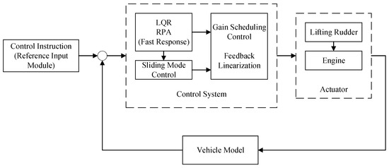
Figure 1.
The control structure diagram of an STT missile.
3.1. Controller Design of Aerodynamic System
3.1.1. Aerodynamic System Controller in Pitch Channel
When studying the aerodynamic system, the influence of the engine’s lateral thrust on the system is not considered; that is, and . Then, the state equation of the aerodynamic system (13) is written as follows:
where is the state vector, is the control vector, and
, , , and represent the coefficient matrix of the pitch channel. Because , system (27) is completely controllable. Considering the control method of the linear variable parameter system, LQR is used here to design the rudder deflection feedback control law, which is expressed as
where . System (27) meets the following quadratic performance indicator:
where , , is the state vector, and is the control vector. By substituting Equation (28) into Equation (27), the closed-loop system is as follows:
where , with , , ,, , , , , , .
To improve the response speed of the STT missile system, the regional pole assignment method is proposed to design the controller of the aerodynamic system. Regional pole assignment includes assigning the poles of a linear system to a certain region , which is in the left half plane of the complex plane, and the stability of the system is called -stability [41]. The controller of the regional pole assignment is solved by transforming the solution problem into a linear matrix inequality (LMI). As shown in Figure 2, the radius is , and the circular region with the center of the circle at is the LMI region [42].
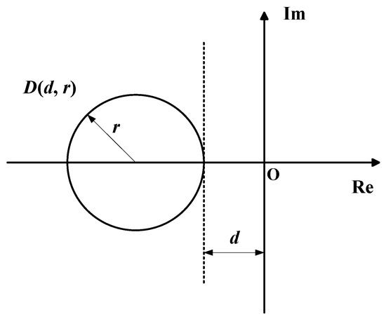
Figure 2.
LMI region .
Region is represented as
where is a complex variable. The characteristic function of LMI region is expressed as
For a given matrix , the matrix has -stability when all its eigenvalues are in the LMI region. And there is a symmetric positive definite matrix such that
The farther the LMI region is from the circle point, that is, the farther the real part of the closed-loop system pole is from the virtual axis, the faster the system responds.
The state feedback controller for the regional pole assignment of system (27) is denoted as
By substituting controller (34) into system (27), the closed-loop system is
According to the regional pole assignment method, the closed-loop pole of system (35) is assigned to LMI region . If there exists a positive definite symmetric matrix , the following inequality is satisfied:
Then, the system is in the circle and asymptotically stable. Let ; substituting this into inequality (36), we obtain
The matrices and are solved by LMI, and then the controller gain is obtained:
3.1.2. Aerodynamic System Controller in Yaw Channel
In the aerodynamic system, the influence of the engine’s lateral thrust is not considered; that is, and . Then, the state equation of aerodynamic system (26) is written as
where is the state vector, is the control vector, and
, , , and represent the coefficient matrix of the yaw channel. Because , system (39) is completely controllable. The LQR is chosen here to design the rudder deflection feedback control law, which is expressed as
where . System (39) meets the quadratic performance indicator (29). By substituting Equation (40) into Equation (39), the closed-loop system is
where , with , , , , , , , , , .
To improve the response speed of the STT missile system, a regional pole assignment method is used to design the controller of the aerodynamic system. The state feedback controller for the regional pole assignment of system (39) is denoted as
By substituting controller (42) into system (39), the closed-loop system is
According to the regional pole assignment method, the closed-loop pole of system (43) is assigned to LMI region . If there exists a positive definite symmetric matrix , the following inequality is satisfied:
Then, the system is in the circle and asymptotically stable. Let ; substituting this into inequality (44), we obtain
The matrices and are solved by LMI, and then the controller gain is obtained:
3.2. Controller Design of Lateral Thrust System
For the compound control hypersonic STT missile, when the aerodynamic rudder is saturated, the control force cannot be generated continuously. In this case, the lateral thrust generated by the engine is added to the system.
3.2.1. Lateral Thrust System Controller in Pitch Channel
The system model with lateral thrust is described as
where the state vector of the thrust system is , and is the control vector.
, with , , . Because , system (47) is completely controllable. The sliding mode control method is chosen because the lateral thrust control system is controlled by an on–off mode. To solve the sliding mode controller, a sliding mode surface needs to be designed. First, system (47) is converted to the following standard form:
where , , , , , , and are the variables of the standard form matrix; is the state vector of the standard equation; and , is called the transformation matrix, written as .
The sliding mode surface is defined as and satisfies
During the selection of to , it is ensured that the system state converges to zero and meets the following sliding mode arrival conditions:
The sliding mode controller is defined as
where is the lateral thrust produced by the pitch channel engine. To mitigate the jump in the thrust amplitude of the engine and save fuel consumption, the lateral thrust system is designed to output thrust with different amplitude sizes for the STT missile. When the system state is far away from the sliding surface, the engine with larger thrust will work. When the system state is close to the sliding surface, the engine with smaller thrust works. In this case, the variable structure controller of the system is
where is the larger value of the engine’s lateral thrust, is the smaller value of the engine’s lateral thrust, and and are the boundary constants of the sliding mode surface.
When an STT missile flies at different altitudes, gain scheduling is used to control the missile system of the different flight altitudes. The STT missile flight control system can be regarded as a fixed system with multiple steady-state operating points, each of which has a fixed stability control gain. Different flight altitudes are regarded as different stable operating points, and the missile controller at each altitude is designed. Therefore, the gain scheduling design method is appropriate. When limited to space, the controller of a steady-state operating point is designed every 2 km. The LQR controller, pole assignment controller, and sliding mode controller of the pitch channel are denoted, respectively, at different heights as
3.2.2. Lateral Thrust System Controller in Yaw Channel
The system model of the yaw channel with lateral thrust is described as
where the state vector of the thrust system is , and is the control vector.
, with , , . Because , system (54) is completely controllable. To solve the sliding mode controller, a sliding mode surface needs to be designed. First, system (54) is converted to the following standard form:
where , , , , , , and are the variables of the standard form matrix; is the state vector of the standard equation; and , is called the transformation matrix, written as .
The sliding mode surface is defined as and satisfies
During the selection of to , it is ensured that the system state converges to zero and meets the following sliding mode arrival conditions:
The sliding mode controller is defined as
where is the lateral thrust of the yaw channel engine. To mitigate the jump in the thrust amplitude of the engine and save fuel consumption, the lateral thrust system is designed to output thrust with different amplitude sizes for the STT missile. In this case, the variable structure controller of the system is
where is the larger value of the engine’s lateral thrust, and is the smaller value of the engine’s lateral thrust.
When an STT missile flies at different altitudes, gain scheduling is used to control the missile system at different flight altitudes. When limited to space, the controller of a steady-state operating point is designed every 2 km. The LQR controller, pole assignment controller, and sliding mode controller of the yaw channel are denoted, respectively, at different heights as
4. Simulation
In this section, the gain scheduling steady-state controller based on a regional pole assignment is given. Then, the fast response of the pitch channel and yaw channel of STT missiles at different flight altitudes is simulated. By comparing the response speed of the compound control system when the aerodynamic system is LQR control or regional pole assignment, the importance of designing regional pole assignment is highlighted.
4.1. Gain Scheduling Controller
The parameters of the STT missile control system are shown in Table 2.
Table 2.
Parameters of STT missile.
In the STT missile control system, the aerodynamic parameters are , , , , , and . Throughout the change in actual aerodynamic parameters, and are approximately proportional, and and are approximately proportional. Herein, the proportional relations are referred to as and separately. The proportional coefficients are and .
According to the design requirements, such as the response speed and oscillation frequency of the system, the center and radius of the circular region for pole placement are determined. Since the system is required to have a response time of less than 0.3 s and a maximum oscillation frequency of less than 300 rad/s, considering the positions of the dominant poles and other poles, the pole region is set as . The poles of steady-state operating points at different flight altitudes of STT missiles and corresponding controllers are given below. When limited to space, the poles and controllers of a steady-state operating point are shown every 2 km; the pole region is denoted as to at different flight altitudes.
Steady-state operating point 1 (25–26 km):
The pole of the region is [−580, −25, −9.5, −0.1], and the controller at the pole is [−0.0884, 0.8773, −1.6138, 2.934].
Steady-state operating point 2 (27–28 km):
The pole of the region is [−570, −20, −9, −0.1], and the controller at the pole is [−0.0573, 1.147, −2.19, 2.823].
Steady-state operating point 3 (29–30 km):
The pole of the region is [−590, −25, −10, −0.5], and the controller at the pole is [−0.0784, 1.5681, −2.9972, 2.8231].
Steady-state operating point 4 (31–32 km):
The pole of the region is [−585, −20, −8.5, −0.3], and the controller at the pole is [−0.2137, 2.1205, −4.073, 2.8054].
Steady-state operating point 5 (33–34 km):
The pole of the region is [−575, −26, −9.2, −0.4], and the controller at the pole is [−0.2925, 2.9034, −5.5815, 2.8055].
Steady-state operating point 6 (35–36 km):
The pole of the region is [−586, −28, −10, −0.2], and the controller at the pole is [−0.4009, 3.9783, −7.6543, 2.8055].
Steady-state operating point 7 (37–38 km):
The pole of the region is [−592, −25, −8.7, −0.1], and the controller at the pole is [−0.4362, 4.3292, −8.877, 2.3389].
Steady-state operating point 8 (39–40 km):
The pole of the region is [−585, −26, −9.3, −0.3], and the controller at the pole is [−0.3682, 7.3652, −14.137, 2.8233].
Because the pitch channel and yaw channel are axisymmetric to each other, the controllers obtained by pole assignment are equal in these two channels. The pole assignment controller is substituted into system (35) and system (43), respectively, and combined with sliding mode control, the dual channel compound control design is realized.
4.2. Simulation Analysis
In this subsection, simulations of the STT missile at 25 km, 30 km, and 35 km are given, respectively. At each altitude, the pitch channel and yaw channel, which are axisymmetric, are simulated. Each channel is compared when the aerodynamic system of the compound control system is LQR and regional pole assignment (RPA), respectively.
- (1)
- Simulation at 25 km
The acceleration command for tracking at 25 km is . The simulations of the pitch channel and yaw channel are shown in Figure 3, Figure 4, Figure 5, Figure 6 and Figure 7.
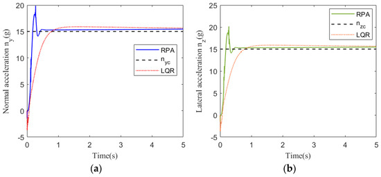
Figure 3.
Acceleration tracking response at 25 km: (a) pitch channel; (b) yaw channel.
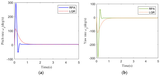
Figure 4.
Rate response at 25 km: (a) pitch channel; (b) yaw channel.
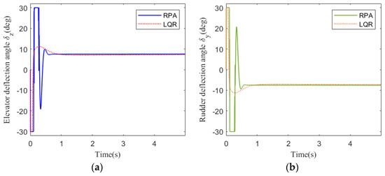
Figure 5.
Deflection angle response at 25 km: (a) pitch channel; (b) yaw channel.
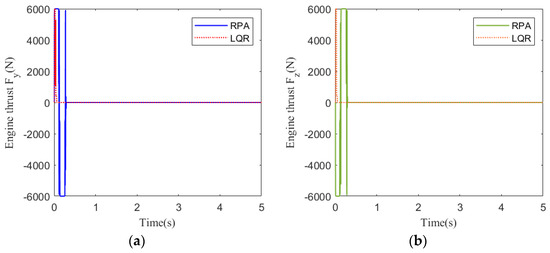
Figure 6.
Engine thrust response at 25 km: (a) pitch channel; (b) yaw channel.
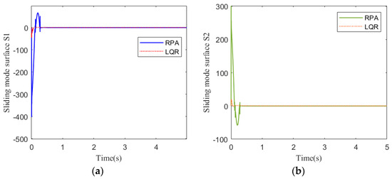
Figure 7.
Sliding mode surface response at 25 km: (a) pitch channel; (b) yaw channel.
Figure 3 shows the acceleration tracking response of the STT missile at 25 km. It can be seen from Figure 3a,b that the response speed of the compound control system based on regional pole assignment (RPA) is significantly faster than that of the compound control system based on LQR. Although the RPA response curve has a brief overshoot, it returns to a stable state instantaneously. From the comparison of (a) and (b) in Figure 4, Figure 5, and Figure 7, the simulation curves are equal in value but opposite in direction, reflecting the mutual axisymmetric structure of the pitch channel and yaw channel. Figure 4 is the angular rate response curve. The compound control system based on LQR converges to the zero axis slowly, while the response curve of the compound control system based on RPA has a reverse rate, but the system quickly returns to a stable state. It meets the design requirements of a fast response system. Figure 5 is the response curve of the rudder deflection angle. Figure 6 shows the thrust response curve of the engine. When the rudder deflection angle in Figure 5 reaches 30 degrees of saturation, the engine starts working at the corresponding time in Figure 6. The sliding mode surface in Figure 7 has a brief fluctuation and then quickly returns to a stable state.
- (2)
- Simulation at 30 km
The acceleration command for tracking at 30 km is . The simulations of the pitch channel and yaw channel are shown in Figure 8, Figure 9, Figure 10, Figure 11 and Figure 12.
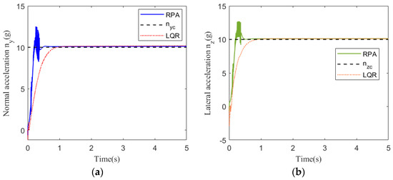
Figure 8.
Acceleration tracking response at 30 km: (a) pitch channel; (b) yaw channel.
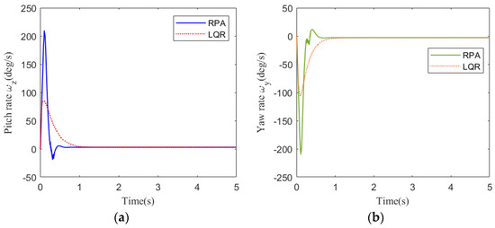
Figure 9.
Rate response at 30 km: (a) pitch channel; (b) yaw channel.
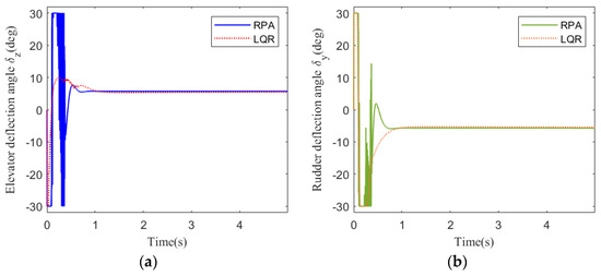
Figure 10.
Deflection angle response at 30 km: (a) pitch channel; (b) yaw channel.
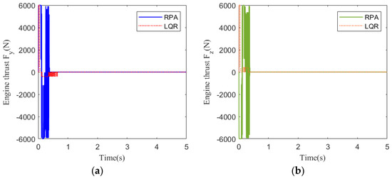
Figure 11.
Engine thrust response at 30 km: (a) pitch channel; (b) yaw channel.
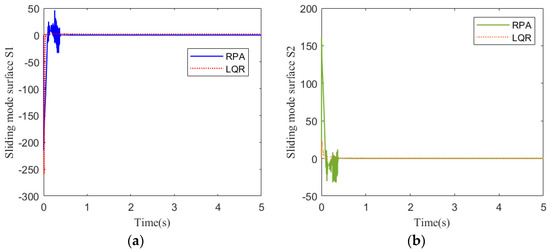
Figure 12.
Sliding mode surface response at 30 km: (a) pitch channel; (b) yaw channel.
Figure 8 shows the acceleration tracking response of the STT missile at 30 km. It can be seen from Figure 8a,b that the response speed of the compound control system based on RPA is significantly faster than that of the compound control system based on LQR. Although the RPA response curve has a brief overshoot, it returns to a stable state instantaneously. It meets the need for a rapid response system. From the comparison of (a) and (b) in Figure 9, Figure 10, and Figure 12, the simulation curves are equal in value but opposite in direction, reflecting the mutual axisymmetric structure of the pitch channel and yaw channel. Figure 9 is the angular rate response curve. The response curve of the compound control system based on RPA quickly returns to a stable state. Figure 10 is the response curve of the rudder deflection angle. Figure 11 shows the thrust response curve of the engine. When the rudder deflection angle in Figure 10 reaches a saturated state, the engine starts working at the corresponding time in Figure 11. The sliding mode surface in Figure 12 has a short vibration at the initial moment and then quickly converges to a stable state.
- (3)
- Simulation at 35 km
The acceleration command for tracking at 35 km is . The simulations of the pitch channel and yaw channel are shown in Figure 13, Figure 14, Figure 15, Figure 16 and Figure 17.
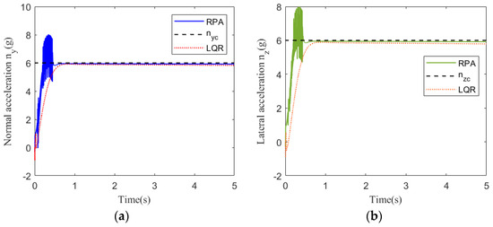
Figure 13.
Acceleration tracking response at 35 km: (a) pitch channel; (b) yaw channel.
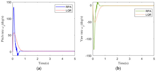
Figure 14.
Rate response at 35 km: (a) pitch channel; (b) yaw channel.
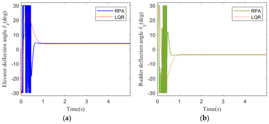
Figure 15.
Deflection angle response at 35 km: (a) pitch channel; (b) yaw channel.
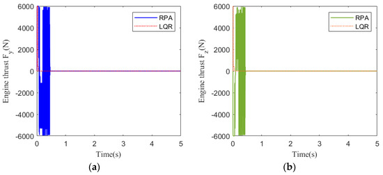
Figure 16.
Engine thrust response at 35 km: (a) pitch channel; (b) yaw channel.
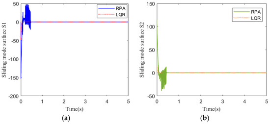
Figure 17.
Sliding mode surface response at 35 km: (a) pitch channel; (b) yaw channel.
Figure 13 shows the acceleration tracking response of the STT missile at 35 km. It can be seen from Figure 13a,b that the response speed of the compound control system based on RPA is significantly faster than that of the compound control system based on LQR. From the comparison of (a) and (b) in Figure 14, Figure 15 and Figure 17, the simulation curves are equal in value but opposite in direction, reflecting the mutual axisymmetric structure of the pitch channel and yaw channel. Figure 15 is the response curve of the rudder deflection angle. Figure 16 shows the thrust response curve of the engine. When the rudder deflection angle in Figure 15 reaches a saturated state, the engine starts working at the corresponding time in Figure 16. The sliding mode surface in Figure 17 has a short vibration at the initial moment and then quickly converges to a stable state.
In the simulation diagram, the curve from simulation case (1) at 25 km is smooth; in simulation case (2), there is weak oscillation in the curve at 30 km; and simulation case (3) has oscillations in the curve at 35 km. With the increase in flight height, the oscillation gradually increases. This is because the increase in flight height decreases the air density, and the aerodynamic coefficient of the aircraft changes, resulting in a very short period of small amplitude oscillation in the system. From the point of view of requiring a fast response of the system, weak oscillation has little effect on the overall performance of the system, so it is beneficial that the controller designed by regional pole assignment can achieve a fast response of the system under the condition of small oscillation.
5. Conclusions
An aerodynamic and lateral thrust compound control method based on regional pole assignment is proposed to improve the response speed of the STT missile system. In the aerodynamic control system, the linear quadratic controller is used to design the controller, and the sliding mode control method is used to design the controller of the lateral thrust system. Regional pole assignment is introduced into the aerodynamic system to improve the response speed of the system. The problems of regional pole assignment and system stability are solved by linear matrix inequalities. At different flight altitudes, gain scheduling is used to control the missile system. Compared to previous designs of time-varying compound control systems for STT missiles or hypersonic vehicles, in order to meet the practical requirement of a fast response for the vehicle, this time-varying compound control strategy can achieve faster tracking responses and altitude control for the STT missile. Aiming at the axial symmetrical structure of the STT missile, the control system of the pitch channel and yaw channel is simulated. The response time of the designed compound control system is 0.2 s faster than that of the previous compound control scheme, which verifies the effectiveness of the fast response method of the designed compound control system.
Author Contributions
Conceptualization, H.W. and D.Z.; methodology, H.W.; software, H.W.; validation, H.W. and D.Z.; formal analysis, Y.Z. and D.Z.; investigation, H.W.; resources, H.W. and D.Z.; data curation, H.W. and Y.Z.; writing—original draft preparation, H.W.; writing—review and editing, H.W. and D.Z.; visualization, H.W.; supervision, D.Z.; project administration, D.Z.; funding acquisition, D.Z. All authors have read and agreed to the published version of the manuscript.
Funding
This research was funded by the National Natural Science Foundation of China, grant number 61773142.
Data Availability Statement
The original contributions presented in the study are included in the article, further inquiries can be directed to the corresponding authors.
Conflicts of Interest
The authors declare no conflicts of interest.
References
- Boretti, A. Hydrogen hypersonic combined cycle propulsion: Advancements, challenges, and applications. Int. J. Hydrogen Energy 2024, 55, 394–399. [Google Scholar] [CrossRef]
- Zhu, C.; Xu, G.; Wei, C.; Cai, D.; Yu, Y. Impact-Time-Control Guidance Law for Hypersonic Missiles in Terminal Phase. IEEE Access 2020, 8, 44611–44621. [Google Scholar] [CrossRef]
- Bao, C.; Wang, P.; Tang, G. Integrated Guidance and Control for Hypersonic Morphing Missile Based on Variable Span Auxiliary Control. Int. J. Aerosp. Eng. 2019, 2019, 6413410. [Google Scholar] [CrossRef]
- Du, X.; Yang, Q.; Yang, H.; Bai, J.; Shi, Y. Infrared radiation characteristics of dagger-type hypersonic missile. Chin. J. Aeronaut. 2024, 37, 137–150. [Google Scholar] [CrossRef]
- Bai, C.; Lu, F.; Xu, X. Hybrid BTT/STT missile autopilot design. Aircr. Eng. Aerosp. Technol. 2017, 89, 809–814. [Google Scholar] [CrossRef]
- Ramteke, V.; Kothari, M. Accessibility Analysis and Robust Control Design of Dual-Spin Projectiles. J. Guid. Control Dyn. 2025, 48, 575–590. [Google Scholar] [CrossRef]
- Wang, Z.; Hao, Y. Reinforcement learning adaptive risk-sensitive fault-tolerant IGC method for a class of STT missile. Nonlinear Dyn. 2024, 112, 18195–18218. [Google Scholar] [CrossRef]
- Wang, Z.; Hao, Y.T.; Liu, J.L.; Bai, Y.F.; Yu, D.X. Reinforcement learning-adaptive fault-tolerant IGC method for a class of aircraft with non-affine characteristics and multiple uncertainties. Aeronaut. J. 2024, 129, 84–106. [Google Scholar] [CrossRef]
- Li, J.; Song, S.; Shi, X. Partial state-constrained integrated guidance and control for an STT missile with self-adjusting prescribed performance via non-barrier Lyapunov function method. Trans. Inst. Meas. Control, 2024; (early access). [Google Scholar] [CrossRef]
- Zou, Z.; Xu, P.; Chen, Y.; Yao, L.; Fu, C. Application of artificial intelligence in turbomachinery aerodynamics: Progresses and challenges. Artif. Intell. Rev. 2024, 57, 222. [Google Scholar] [CrossRef]
- Morlier, J.; Abu Salem, K.; Giuseppe, P.; Vittorio, C.; Vincenzo, B.; Davide, Z.; Mario, C.; Kokkolaras, M. Tools and methodologies for box-wing aircraft conceptual aerodynamic design and aeromechanic analysis. Mech. Ind. 2021, 22, 39. [Google Scholar] [CrossRef]
- Jiang, L.; Dong, C.; Pan, X.; Chen, G. Aerodynamic/control coupling optimization of reentry vehicle under wide speed range. Acta Mech. Sin. 2024, 41, 324259. [Google Scholar] [CrossRef]
- Rao, H.; Shi, Y.; Bai, J.; Chen, Y.; Yang, T.; Li, J. Aerodynamic Optimization Design of Supersonic Wing Based on Discrete Adjoint. Aerospace 2023, 10, 420. [Google Scholar] [CrossRef]
- Taufik, N.Z.B.; Zaidaan, S.; Mahmoud, E.; Abdallah, A.M.; Manaa, Z.; Abro, G.E.M.; Taib, M.N. Design and Analysis of the Effect of Trimmable Vertical Stabilizers for Enhanced Aircraft Maneuverability and Directional Stability. In Proceedings of the 2024 IEEE 12th Conference on Systems, Process & Control (ICSPC), Malacca, Malaysia, 7 December 2024; pp. 251–256. [Google Scholar]
- Yin, X.; Ma, H.; Zhang, W.; An, H.; Ke, Z.; Wang, L.; Nie, B. Analysis of the Controllability and Stability of a Hybrid High-Speed Compound Helicopter with a New Configuration. Int. J. Aeronaut. Space Sci. 2024, 25, 1205–1218. [Google Scholar] [CrossRef]
- Cockin, E.; Wang, X. Robust Sliding Mode Control for Air-to-Air Missile. arXiv 2024, arXiv:2411.06754. [Google Scholar]
- Hu, Y.; Yan, H.; Zhang, H.; Wang, M.; Zeng, L. Robust Adaptive Fixed-Time Sliding-Mode Control for Uncertain Robotic Systems With Input Saturation. IEEE Trans. Cybern. 2023, 53, 2636–2646. [Google Scholar] [CrossRef]
- Meng, Z.; Liu, L.; Duan, X.; Zhu, L.; Xu, Z. Compound control for electromagnetic linear load simulator. Trans. Inst. Meas. Control 2023, 45, 3020–3030. [Google Scholar] [CrossRef]
- Zhou, X.; Wang, W.; Shi, Y. Neural Network/PID Adaptive Compound Control Based on RBFNN Identification Modeling for an Aerial Inertially Stabilized Platform. IEEE Trans. Ind. Electron. 2024, 71, 16514–16522. [Google Scholar] [CrossRef]
- Lei, X.; Fu, F.; Wang, R. A High-Performance Compound Control Method for a Three-Axis Inertially Stabilized Platform under Multiple Disturbances. Symmetry 2022, 14, 1848. [Google Scholar] [CrossRef]
- Mu, Y.; Qi, L.; Sun, M.; Han, W. An Improved Deviation Coupling Control Method for Speed Synchronization of Multi-Motor Systems. Appl. Sci. 2024, 14, 5300. [Google Scholar] [CrossRef]
- Tang, Y.; Xu, W.; Liu, Y.; Dong, D. Dynamic Performance Enhancement Method Based on Improved Model Reference Adaptive System for SPMSM Sensorless Drives. IEEE Access 2021, 9, 135012–135023. [Google Scholar] [CrossRef]
- Zhang, Y.; Lu, H.; Li, M.; Liu, X. Speed Regulation and Optimization of Sensorless System of Permanent Magnet Synchronous Motor. Machines 2023, 11, 656. [Google Scholar] [CrossRef]
- Liu, X.; Wang, Y.; Wang, M. Speed Fluctuation Suppression Strategy of Servo System with Flexible Load Based on Pole Assignment Fuzzy Adaptive PID. Mathematics 2022, 10, 3962. [Google Scholar] [CrossRef]
- Zhang, Z.; Wu, J.; Zheng, L.; Xie, D.; Tang, X. An Inductor Current Sensorless Control Strategy Based on Modified VSG Method for Single-Phase Microgrid Application With Seamless Transfer Capability. Front. Energy Res. 2021, 9, 752422. [Google Scholar] [CrossRef]
- Zhang, M.; Xu, C.; Li, L.; Wang, Z.; Zong, X. Optimization of PID controller for stepper motor speed control system based on improved sparrow search algorithm. Proc. Inst. Mech. Eng. Part C J. Mech. Eng. Sci. 2024, 238, 9397–9411. [Google Scholar] [CrossRef]
- He, C.; Zhou, D.; Sheng, W.; Xu, M.; Xi, Q.; Chen, Q. Fuzzy-PID controller design for RGV speed track based on improved PSO algorithm. J. Braz. Soc. Mech. Sci. Eng. 2024, 46, 669. [Google Scholar] [CrossRef]
- Zou, X.; Ding, H.; Li, J. Sliding mode speed control of permanent magnet synchronous motor based on improved reaching law. COMPEL—Int. J. Comput. Math. Electr. Electron. Eng. 2022, 42, 1335–1348. [Google Scholar] [CrossRef]
- Du, K.; Xiao, B.; Song, Z.; Xu, Y.; Tang, Z.; Xu, W.; Duan, H. A novel self-adaptation and sorting selection-based differential evolutionary algorithm applied to water distribution system optimization. J. Water Supply Res. Technol.-Aqua 2022, 71, 1068–1082. [Google Scholar] [CrossRef]
- Wang, M.; Wang, S.; Wang, H.; Li, C.; Qi, X.; Xu, J.; Xiao, Q. Functional waveform pulse variable speed stirring to improve mechanistic analysis and experimental study on the purification efficiency of zinc sulfate solution. Int. J. Chem. React. Eng. 2023, 21, 23–39. [Google Scholar] [CrossRef]
- Huang, C.-L.; Wu, C.-J.; Yang, S.-C. Full-Region Sensorless BLDC Drive for Permanent Magnet Motor Using Pulse Amplitude Modulation With DC Current Sensing. IEEE Trans. Ind. Electron. 2021, 68, 11234–11244. [Google Scholar] [CrossRef]
- Xu, W.; Zhang, J.; Wen, H. Robust anti-pitching control for high-speed multihull without velocity measurements. Proc. Inst. Mech. Eng. Part M J. Eng. Marit. Environ. 2022, 237, 120–131. [Google Scholar] [CrossRef]
- Poureh, A.; Chamani, M.; Bahri, A. Nonlinear analysis of gain scheduled controllers for the NREL 5-MW turbine blade pitch control system. Int. J. Electr. Power Energy Syst. 2023, 145, 108578. [Google Scholar] [CrossRef]
- Li, P.; Li, P.; Zhao, J.; Zhang, B. Robust gain-scheduling static output-feedback H∞ control of vehicle lateral stability with heuristic approach. Inf. Sci. 2021, 546, 220–233. [Google Scholar] [CrossRef]
- Butkus, M.; Levišauskas, D.; Galvanauskas, V. Simple Gain-Scheduled Control System for Dissolved Oxygen Control in Bioreactors. Processes 2021, 9, 1493. [Google Scholar] [CrossRef]
- Liu, J.; Ma, Y.; Zhu, L.; Zhao, H.; Liu, H.; Yu, D. Improved Gain Scheduling Control and Its Application to Aero-Engine LPV Synthesis. Energies 2020, 13, 5967. [Google Scholar] [CrossRef]
- Bianchi, F.D.; Sánchez-Peña, R.S. A method for reducing implementation complexity in linear parameter-varying controllers. Automatica 2022, 146, 110588. [Google Scholar] [CrossRef]
- Zhang, K.; Zhou, B.; Jiang, H.; Duan, G. Event-triggered and self-triggered gain scheduling control of input constrained systems with applications to the spacecraft rendezvous. Int. J. Robust Nonlinear Control 2021, 31, 4629–4646. [Google Scholar] [CrossRef]
- Samia, C.; Houssem, J. The Use of a Heuristic Optimization Method to Improve the Design of a Discrete-time Gain Scheduling Control. Int. J. Control Autom. Syst. 2021, 19, 1836–1846. [Google Scholar] [CrossRef]
- Wang, Q.; Xue, A. Robust control for spacecraft rendezvous system with actuator unsymmetrical saturation: A gain scheduling approach. Int. J. Control 2017, 91, 1241–1250. [Google Scholar] [CrossRef]
- Li, Y.; Du, H.; He, Z.; Zhou, W. Robust Control for the IPT System With Parametric Uncertainty Using LMI Pole Constraints. IEEE Trans. Power Electron. 2020, 35, 1022–1035. [Google Scholar] [CrossRef]
- Xiong, S.; Chen, M.; Wei, Z. Tracking flight control of UAV based on multiple regions pole assignment method. Aerosp. Sci. Technol. 2022, 129, 107848. [Google Scholar] [CrossRef]
Disclaimer/Publisher’s Note: The statements, opinions and data contained in all publications are solely those of the individual author(s) and contributor(s) and not of MDPI and/or the editor(s). MDPI and/or the editor(s) disclaim responsibility for any injury to people or property resulting from any ideas, methods, instructions or products referred to in the content. |
© 2025 by the authors. Licensee MDPI, Basel, Switzerland. This article is an open access article distributed under the terms and conditions of the Creative Commons Attribution (CC BY) license (https://creativecommons.org/licenses/by/4.0/).