Abstract
With the advance in technology in driving vehicles, there is currently more emphasis on developing advanced control systems for better road handling stability and ride comfort. However, one of the challenging problems in the design and implementation of intelligent suspension systems is that there is currently no solution supporting the export of generic suspension models and control components for integration into embedded Electronic Control Units (ECUs). This significantly limits the usage of embedded suspension components in automotive production code software as it requires very high efforts in implementation, manual testing, and fulfilling coding requirements. This paper introduces a new dynamic model of full-car suspension system with semi-active suspension behavior and provides a hybrid sliding mode approach for control of full-car suspension dynamics such that the road handling stability and ride comfort characteristics are ensured. The semi-active suspension model and the hybrid sliding mode controller are implemented as Functional Mock-Up Units (FMUs) conforming to the Functional Mock-Up Interface for embedded systems (eFMI) and are calibrated with a set experimental tests using a 1/5 Soben-car test bench. The methods and prototype implementation proposed in this paper allow both model and controller re-usability and provide a generic way of integrating models and control software into embedded ECUs.
1. Introduction
With the advance in technology in driving vehicles, there is currently more emphasis on developing advanced control systems for better road handling stability and ride comfort. Vehicle suspension systems can be classified into three types, namely, active, passive, and semi-active suspension. Active suspension systems are expensive in terms of cost and energy consumption and provide an active damping force that is generated by using an external power device in response to data from displacement and acceleration sensors installed in the vehicle body. Passive suspension systems provide poor performance in terms of road handling and ride comfort and are composed of passive dampers and conventional springs installed between the wheel axle assembly and the vehicle body [1,2,3,4]. Semi-active suspension systems are economic in terms of cost and energy consumption and provide good suspension performance by using controllable semi-active dampers [5,6,7,8]. Our study is focused on using semi-active suspension systems with Electrorheological (ER) dampers.
Different models and control designs have been proposed in the literature for semi-active suspension systems. In terms of modeling, many studies have used non-parametric modeling approaches that are based on artificial intelligence methods to model the semi-active damping force and suspension dynamics [9,10,11]. Some other studies have used parametric modeling approaches that use physical and mechanical laws and validated the parametric models by a set of parameter identification and validation experiments [12,13,14,15]. In terms of control, many control strategies have been proposed in the literature, including PID control [16], fuzzy Logic control [17,18], optimal control [19,20], LQ/LQG control [21], control [22], and control strategies based on genetic algorithms and neural networks [23,24,25]. However, one of the challenging problems in the design and implementation of intelligent suspension control systems is that there is currently no solution supporting the export of generic suspension models and control components for integration into embedded Electronic Control Units (ECUs). This significantly limits the usage of embedded suspension components in automotive production code software as it requires very high efforts in implementation, manual testing, and fulfilling coding requirements. The application of sliding-mode controllers for semi-active suspension systems has been investigated by many researchers [6,26,27,28]. However, these studies are either limited to applying sliding mode control for quarter-car models or limited to only ride comfort or only road holding. Authors in [26] have considered the use of semi-active suspension systems having Magnetorheological (MR) dampers, which are out of the scope of our study.
In this paper, we introduce a new dynamic model of full-car semi-active suspension systems, and we investigate the usage of a hybrid sliding mode approach for control of full-car suspension dynamics, such that both road handling stability and ride comfort are ensured. The semi-active suspension model and hybrid sliding mode controller are both implemented as Functional Mock-Up Units (FMUs) conforming to the Functional Mock-Up Interface for embedded systems (eFMI). Our implementation allows model and controller re-usability and provides a generic way of integrating models and control software into embedded ECUs. The implemented suspension model and sliding mode controller are calibrated with a set experimental tests using a 1/5 INOVE Soben-car test bench.
The paper is organized as follows: Section 2 introduces a dynamic model of full-car semi-active suspension systems. Section 3 presents the hybrid full-car sliding mode controller that supports both road handling and ride comfort. Section 4 discusses the simulation results and the prototype implementation of the model and controller. Finally, Section 5 presents the conclusions and future work.
2. The Full-Car Suspension Model
Figure 1 demonstrates a symmetrical full-car suspension model having seven degrees of freedom (7 DOF). The model is composed of a sprung mass that represents the car full-body and four unsprung masses that represent the four wheel–axle assemblies. The seven degrees of freedom are represented by the bounces of the four unsprung masses and the bounces, pitching, and rolling movements of the sprung mass. The full-car suspension system consists of four semi-active Electrorheological (ER) dampers and four linear suspension springs located between the unsprung masses and the sprung mass.
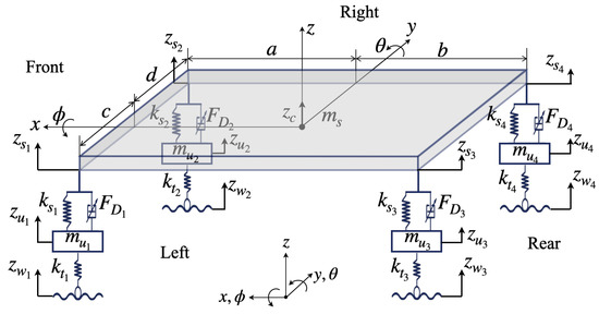
Figure 1.
Schematic of the 7 DOF full-car suspension system.
The equations that describe the full-car suspension model are given by:
where:
where , , and denote the vertical displacement of the vehicle full-body centroid, the pitch angle, and the roll angle, respectively, and , , , , , and denote the vertical displacement of the quarter body, the vertical displacement of the wheel axle, the road disturbance, the controlled damping force, the control input, and the damping time constant, respectively, at suspension i. The matrices that appear in (1) and (2) are expressed as:
where , , and denote the sprung mass, the pitch inertia, and the roll inertia, respectively; , , , , and denote unsprung mass, the passive damping, the stiffness of the suspension spring, the passive stiffness of the damper, and the tire stiffness, respectively, at suspension i; and a, b, c, and d denote the distances between the center of gravity of the vehicle full-body and the centers of the two wheel axes in the front, rear, left, and right sides, respectively.
The roll angle and pitch angle change in a small range, such that ; ; ; and , which implies the following linear relationship:
so that
3. The Sliding Mode Controller
For the controller design, we use the sliding mode control approach to achieve both road handling stability and ride comfort. The sliding mode controller design is based on using a reference model that tracks the desired damping behavior by adaptively adjusting the damping force. The controlled sliding surface represents the error dynamics between the actual behavior of the suspension system and the desired behavior, as defined by the reference model.
3.1. The Reference Model
The reference model is used as an input to the sliding mode controller and represents the desired and ideal suspension behavior in terms of road handling stability and ride comfort.
To achieve the ride comfort driving characteristic, we implement an ideal sky-hook damper in which the four quarter-car bodies are connected to virtual points in the sky, such that the damping force at each quarter-car body is dependent on the absolute velocity of the quarter-car body. The desired suspension behavior for ride comfort is represented by:
where is the coefficient for ideal ride comfort-based damping at suspension i, given by:
and is the maximum sky-hook damping coefficient at suspension i.
To achieve the road handling stability, we implement an ideal ground-hook damper in which the four wheel–axle assemblies are connected to virtual points in the ground, such that the damping force at each quarter-car body is dependent on the absolute velocity of the wheel–axle assembly. The desired suspension behavior for road handling stability is represented by:
where is the coefficient for ideal road handling-based damping at suspension i, given by:
and is the maximum ground-hook damping coefficient at suspension i.
3.2. The Controller
The aim of using a sliding mode controller is to track and minimize the errors in states and dynamics between the full-car suspension system and the desired suspension behavior. The error vectors for both road handling stability and ride comfort are given by:
To ensure that both road handling stability and ride comfort are met, we set the surfaces of sliding mode control as:
where , , , , and are the slopes of the sliding surfaces , , , , and , respectively.
To achieve the ride comfort driving characteristic, we set , so that the error states and dynamics (related to ride comfort) are minimized and kept on the sliding surface . The equivalent damping force for ride comfort is given by:
where denotes the equivalent damping force for ride comfort at the suspension i. To ensure convergence towards the sliding surface , we add discontinuous terms to the damping forces . The resulting sliding mode damping force for ride comfort at suspension is given by:
where , , , and are positive constants.
Similarly, to achieve the road handling driving characteristic, we set , so that the error states and dynamics (related to road handling) are minimized and kept on the sliding surfaces , , , and . The equivalent damping force for road handling at suspension is given by:
To ensure convergence towards the sliding surfaces , , , and , we add discontinuous terms to the damping forces . The resulting sliding mode damping force for road handling at suspension is given by:
where , , , and are positive constants.
To eliminate the chattering behavior that may occur around the sliding surfaces, we replace the signum functions and in (31) and (33) with the saturation functions and , receptively, where is the thickness of the boundary layer, and
The resulting damping force generated by the hybrid sliding mode controller at the suspension is given by:
where is a coefficient that is used to define the driving characteristic, whether it is fully ride comfort (i.e., ) or fully road holding (i.e., ) or proportionally ride comfort and road holding (i.e., ).
To demonstrate the applicability of the concepts presented in this paper, we implemented a prototype and performed a set of experimental and simulation tests. The semi-active suspension model and the hybrid sliding mode controller are both implemented as Functional Mock-Up Units (FMUs) conforming to the Functional Mock-Up Interface for embedded systems (eFMI) [29]. Our implementation allows model and controller re-usability and provides a generic way of integrating models and control software into embedded ECUs. The prototype implementation is validated through a set of experimental tests using 1/5 INOVE Soben-car test bench from GIPSA-Lab at University of Grenoble Alpes (see Figure 2). The test bench has four Electrorheological dampers of type Fludicon and four amplifier modules of type CarCon2; the input of each amplifier module is a PWM signal. Four servomotors of type OMRON are connected to the wheel–axle assemblies to simulate the input road profiles. Matlab/SimulinkTM and FMU control interfaces are used on the Host PC to perform simulation tests on the suspension model and the sliding mode controller. Target PC is used to compile and execute the FMU blocks in real-time simulation.
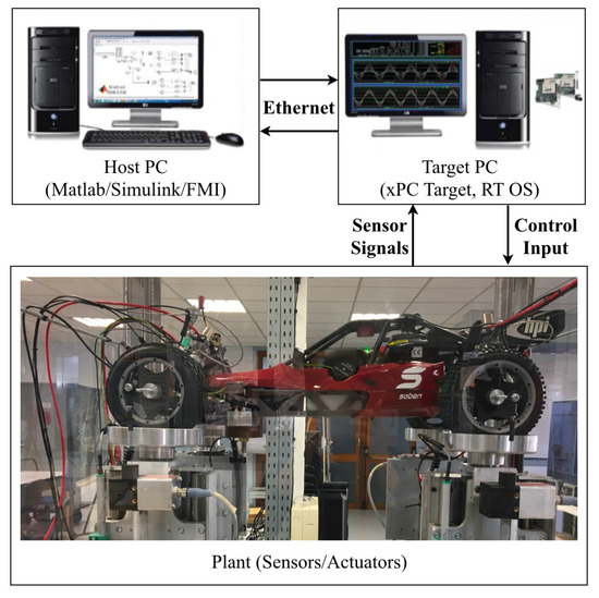
Figure 2.
The test bench used for experimental validation and testing.
4. Prototype and Simulation Results
Table 1 shows the selected numerical values for the suspension model and control parameters. Different random road profiles have been used in this study, and all of them were chosen in correspondence with the ISO 8608 standard of road classification (see Table 2) [30].

Table 1.
Numerical values for the suspension model and control parameters.
Table 2.
ISO 8608 standard of road classification.
Figure 3 shows one of the road profiles used in this study. The road profile is ISO 8608 Class C and has an irregularity coefficient m and a variance of excitation signal 0.1.
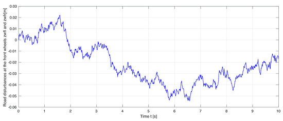
Figure 3.
The road profile.
Figure 4, Figure 5, Figure 6, Figure 7 and Figure 8 demonstrate the experimental and simulation results of the model validation. The vertical displacements of the front and rear unsprung masses (i.e., the wheel–axle assemblies) are presented in Figure 4 and Figure 5. The vertical displacements of the front and rear sprung masses (i.e., the quarter car bodies) together with the vertical displacement of the full-car body centroid are presented in Figure 6, Figure 7 and Figure 8. The experimental data represent the real behavior of the test bench. The simulation results show that the implemented full-car suspension model is highly accurate and precisely captures the suspension dynamics presented in the physical system.
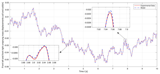
Figure 4.
Model simulation versus experimental data: The vertical displacements of the front wheel-axle assemblies.
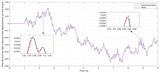
Figure 5.
Model simulation versus experimental data: The vertical displacements of the rear wheel–axle assemblies.
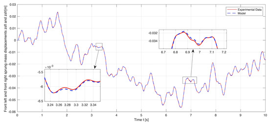
Figure 6.
Model simulation versus experimental data: The vertical displacements of the front quarter-car bodies.
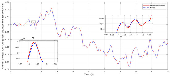
Figure 7.
Model simulation versus experimental data: The vertical displacements of the rear quarter-car bodies.
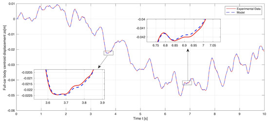
Figure 8.
Model simulation versus experimental data: The vertical displacement of the full-car body centroid.
The simulation results are shown in Figure 9, Figure 10, Figure 11, Figure 12, Figure 13 and Figure 14. The passive and controlled suspension of the full-car body and the four wheel–axle assemblies are compared for three different control objectives: (a) when (i.e., full road handling), (b) when (i.e., full ride comfort), and (c) when (i.e., 40% road handling and 60% ride comfort). When applying the sliding mode control for full ride comfort, the vertical displacement of the full-car body decreases. Similarly, when applying the sliding mode control for full road holding, the vertical displacements of the four wheel–axle assemblies decrease. When the sliding mode control is applied simultaneously for both road handling and ride comfort, the vertical displacements of the full-car body and the wheel–axle assemblies decrease.
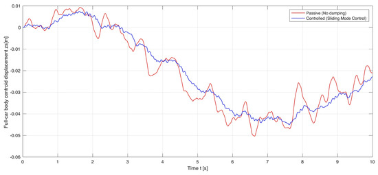
Figure 9.
Passive and controlled displacements of the full-car body centroid: Full-car body centroid displacement when .
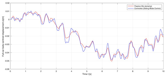
Figure 10.
Passive and controlled displacements of the full-car body centroid: Full-car body centroid displacement when .
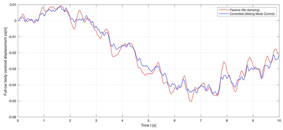
Figure 11.
Passive and controlled displacements of the full-car body centroid: Full-car body centroid displacement when .
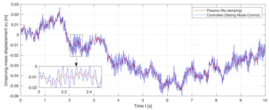
Figure 12.
Passive and controlled displacements of the front wheel–axle assemblies: The vertical displacement of the front wheel–axle assemblies when .
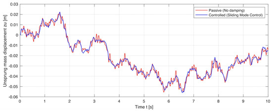
Figure 13.
Passive and controlled displacements of the front wheel–axle assemblies: The vertical displacement of the front wheel–axle assemblies when .
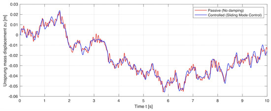
Figure 14.
Passive and controlled displacements of the front wheel–axle assemblies: The vertical displacement of the front wheel–axle assemblies when .
5. Conclusions
In this work, we presented a new dynamic model of a full-car suspension system with semi-active suspension behavior, and we demonstrated how a hybrid sliding mode control approach can be used to support both road handling stability and ride comfort. The full-car model is used to derive a reference model that is used as input to the sliding mode controller. The reference model represents the desired and ideal suspension behavior. To ensure both ride comfort and road handling driving characteristics, we implemented ideal sky-hook and ideal ground-hook virtual dampers. The reference model and the sliding mode controller are used to track and minimize the errors in states and dynamics between the full-car suspension system and the desired suspension behavior. The methods proposed in this paper are validated with a set of experimental tests and simulation results. The experimental data represent the real behavior of the test bench. The simulation results show that the implemented full-car suspension model is highly accurate and precisely captures the suspension dynamics presented in the physical system. The results also show that when the sliding mode control is applied simultaneously for both road handling and ride comfort, the vibrations of the full-car body and the wheel–axle assemblies decrease.
A possible extension of this work would be the exploration of new chattering-free simulation techniques to eliminate—in run time—any chattering effects that may happen around the sliding surfaces; this has been left for future research work. In addition, as a future work, we will explore methods for an accurate modeling of the damping force by using efficient hysteresis models as studied in [31,32].
Author Contributions
Conceptualization, A.A. and M.F.; methodology, A.A.; software, A.A.; validation, A.A.; formal analysis, A.A.; investigation, A.A. and M.S.Q.; data curation, M.F. and Y.B.; writing—original draft preparation, A.A.; writing—review and editing, A.A., M.F., M.S.Q. and Y.B.; visualization, M.S.Q. All authors have read and agreed to the published version of the manuscript.
Funding
This research received no external funding.
Acknowledgments
The experimental work was conducted on the INOVE Soben-Car test bench from GIPSA-Lab at University of Grenoble Alpes.
Conflicts of Interest
The authors declare no conflict of interest.
Glossary
The following parameters are used in the model and controller:
| Symbol | Description | Unit |
| wheel–axle assembly at suspension i | kg | |
| full-car body | kg | |
| pitch angle | rad | |
| roll angle | rad | |
| pitch inertia | kg·m | |
| roll inertia | kg·m | |
| vertical displacement of the full-body centroid | m | |
| vertical displacement of the wheel axle at suspension i | m | |
| vertical displacement of the quarter body at suspension i | m | |
| road disturbance at suspension i | m | |
| damper’s passive damping at suspension i | N·s/m | |
| stiffness of the suspension spring at suspension i | N/m | |
| damper’s passive stiffness at suspension i | N/m | |
| tire stiffness at suspension i | N/m | |
| damping time constant at suspension i | ms | |
| controlled damping force at suspension i | N | |
| ideal sky-hook damping coefficient at suspension i | N·s/m | |
| ideal ground-hook damping coefficient at suspension i | N·s/m | |
| maximum sky-hook damping coefficient at suspension i | N·s/m | |
| maximum ground-hook damping coefficient at suspension i | N·s/m | |
| error vector | - | |
| sliding surface | - | |
| slope of the sliding surface | - | |
| equivalent damping force for ride comfort | N | |
| equivalent damping force for road holding | N | |
| sliding mode damping force for ride comfort | N | |
| sliding mode damping force for road holding | N | |
| coefficient used to define the controller behavior | - |
References
- Yagiz, N.; Hacioglu, Y. Backstepping control of a vehicle with active suspensions. Control Eng. Pract. 2008, 16, 1457–1467. [Google Scholar] [CrossRef]
- Nekoui, M.A.; Hadavi, P. Optimal control of an active suspension system. In Proceedings of the 14th International Power Electronics and Motion Control Conference, Ohrid, Macedonia, 6–8 September 2010. [Google Scholar] [CrossRef]
- Ribbens, W.B. Chapter 7—Vehicle Motion Controls. In Understanding Automotive Electronics, 9th ed.; Butterworth-Heinemann: Waltham, MA, USA, 2017; pp. 343–408. ISBN 9780128104347. [Google Scholar] [CrossRef]
- Yerrawar, R.N.; Arakerimath, R.R. Performance assessment and control policies for semiactive suspension using SIMSCAPE. In Proceedings of the 2016 International Conference on Automatic Control and Dynamic Optimization Techniques (ICACDOT), Pune, India, 9–10 September 2016. [Google Scholar] [CrossRef]
- Gandhi, P.; Adarsh, S.; Ramachandran, K.I. Performance Analysis of Half Car Suspension Model with 4 DOF using PID, LQR, FUZZY and ANFIS Controllers. Procedia Comput. Sci. 2017, 115, 2–13. [Google Scholar] [CrossRef]
- Chen, Y. Skyhook Surface Sliding Mode Control on Semi-Active Vehicle Suspension System for Ride Comfort Enhancement. Engineering 2009, 1, 23–32. [Google Scholar] [CrossRef]
- Savaresi, S.; Silani, E.; Bittanti, S. Acceleration driven damper (ADD): An optimal control algorithm for comfort oriented semi-active suspensions. ASME Trans. J. Dyn. Syst. Meas. Control 2005, 127, 218–229. [Google Scholar] [CrossRef]
- Savaresi, S.; Spelta, C. Mixed sky-hook and ADD: Approaching the filtering limits of a semi-active suspension. ASME Trans. J. Dyn. Syst. Meas. Control 2007, 129, 382–392. [Google Scholar] [CrossRef]
- Choi, S.-B.; Lee, S.-K.; Park, Y.-P. A hysteresis model for the field-dependent damping force of a magnetorheological damper. J. Sound Vib. 2001, 245, 375–383. [Google Scholar] [CrossRef]
- Gaul, L.; Nitsche, R. Friction control for vibration suppression. Mech. Syst. Signal Process. 2000, 14, 139–150. [Google Scholar] [CrossRef]
- Kim, Y.; Langari, R.; Hurlebaus, S. Semiactive nonlinear control of a building with a magnetorheological damper system. Mech. Syst. Signal Process. 2009, 23, 300–315. [Google Scholar] [CrossRef]
- Guo, S.; Yang, S.; Pan, C. Dynamic modeling of magnetorheological damper behaviors. J. Intell. Mater. Syst. Struct. 2006, 17, 3–14. [Google Scholar] [CrossRef]
- Dyke, S.; Spencer, B., Jr.; Sain, M.; Carlson, J. Modeling and control of magnetorheological dampers for seismic response reduction. Smart Mater. Struct. 1996, 5, 565. [Google Scholar] [CrossRef]
- Kamath, G.M.; Wereley, N.M. A nonlinear viscoelastic-plastic model for electrorheological fluids. Smart Mater. Struct. 1997, 6, 351. [Google Scholar] [CrossRef]
- Makris, N.; Burton, S.A.; Taylor, D.P. Electrorheological damper with annular ducts for seismic protection applications. Smart Mater. Struct. 1996, 5, 551. [Google Scholar] [CrossRef]
- Rao, K.D. Modeling, Simulation and Control of Semi Active Suspension System for Automobiles under MATLAB Simulink using PID Controller. IFAC Proc. Vol. 2014, 47, 827–831. [Google Scholar] [CrossRef]
- Zareh, S.H.; Khayyat, A.A.A. Fuzzy inverse model of magnetorheological dampers for semi-active vibration control of an eleven-degrees of freedom suspension system. J. Syst. Des. Dyn. 2011, 5, 1485–1497. [Google Scholar] [CrossRef]
- Takahashi, M.; Kumamaru, T.; Yoshida, K. Integrated controller design for automotive semi-active suspension considering vehicle behavior with steering input. J. Syst. Des. Dyn. 2010, 4, 712–724. [Google Scholar] [CrossRef]
- Passenberg, B.; Caines, P.E.; Leibold, M.; Stursberg, O.; Buss, M. Optimal control for hybrid systems with partitioned state space. IEEE Trans. Autom. Control 2013, 58, 2131–2136. [Google Scholar] [CrossRef]
- Prabakar, R.S.; Sujatha, C.; Narayanan, S. Optimal semi-active preview control response of a half car vehicle model with magnetorheological damper. J. Sound Vib. 2009, 326, 400–420. [Google Scholar] [CrossRef]
- Unger, A.; Schimmack, F.; Lohmann, B.; Schwarz, R. Application of LQ-based semi-active suspension control in a vehicle. Control Eng. Pract. 2013, 21, 1841–1850. [Google Scholar] [CrossRef]
- Fallah, M.S.; Bhat, R.; Xie, W.F. H∞ robust control of semi-active Macpherson suspension system: New applied design. Veh. Syst. Dyn. 2010, 48, 339–360. [Google Scholar] [CrossRef]
- Sun, L.; Cai, X.; Yang, J. Genetic algorithm-based optimum vehicle suspension design using minimum dynamic pavement load as a design criterion. J. Sound Vib. 2007, 301, 18–27. [Google Scholar] [CrossRef]
- Zapateiro, M.; Luo, N.; Karimi, H.R.; Vehi, J. Vibration control of a class of semiactive suspension system using neural network and backstepping techniques. Mech. Syst. Signal Process. 2009, 23, 1946–1953. [Google Scholar] [CrossRef]
- Guo, D.L.; Hu, H.Y.; Yi, J.Q. Neural network control for a semi-active vehicle suspension with a magnetorheological damper. J. Vib. Control 2004, 10, 461–471. [Google Scholar] [CrossRef]
- Yokoyama, M.; Hedrick, J.K.; Toyama, S. A model following sliding mode controller for semi-active suspension systems with MR dampers. In Proceedings of the 2001 American Control Conference, (Cat. No. 01CH37148), Arlington, VA, USA, 25–27 June 2001; Volume 4, pp. 2652–2657. [Google Scholar] [CrossRef]
- Alvarez-Sánchez, E. A Quarter-Car Suspension System: Car Body Mass Estimator and Sliding Mode Control. Procedia Technol. 2013, 7, 208–214. [Google Scholar] [CrossRef]
- Hongbin, R.; Yuzhuang, Z.; Sizhong, C.; Gang, L. State observer based adaptive sliding mode control for semi-active suspension systems. J. Vibroeng. 2015, 17, 1464–1475. [Google Scholar]
- Available online: https://emphysis.github.io/pages/downloads/efmi_specification_1.0.0-alpha.3.html/ (accessed on 20 May 2021).
- Kropáč, O.; Múčka, P. Classification scheme for random longitudinal road unevenness considering road waviness and vehicle response. Shock Vib. 2009, 16, 273–289. [Google Scholar] [CrossRef][Green Version]
- Vaiana, N.; Sessa, S.; Marmo, F.; Rosati, L. A class of uniaxial phenomenological models for simulating hysteretic phenomena in rate-independent mechanical systems and materials. Nonlinear Dyn. 2018, 93, 1647–1669. [Google Scholar] [CrossRef]
- Vaiana, N.; Sessa, S.; Rosati, L. A generalized class of uniaxial rate-independent models for simulating asymmetric mechanical hysteresis phenomena. Mech. Syst. Signal Process. 2021, 146, 106984. [Google Scholar] [CrossRef]
Publisher’s Note: MDPI stays neutral with regard to jurisdictional claims in published maps and institutional affiliations. |
© 2021 by the authors. Licensee MDPI, Basel, Switzerland. This article is an open access article distributed under the terms and conditions of the Creative Commons Attribution (CC BY) license (https://creativecommons.org/licenses/by/4.0/).