
Research on Simulation Calculation of the Safety of Tight-Lock Coupler Curve Coupling


Abstract
:1. Introduction
- We combined with the actual situation on the line of Nanchang Rail Transit Line 4, comprehensive consideration of the geometric offset of the vehicle, wheel-rail clearance, transverse offset of the axle and bogie, transverse offset between bogie and car body, quasi-static offset and other factors on the impact of the continuous vehicle in the operation process, to obtain the maximum transverse offset of the train in the curve rescue continuous process.
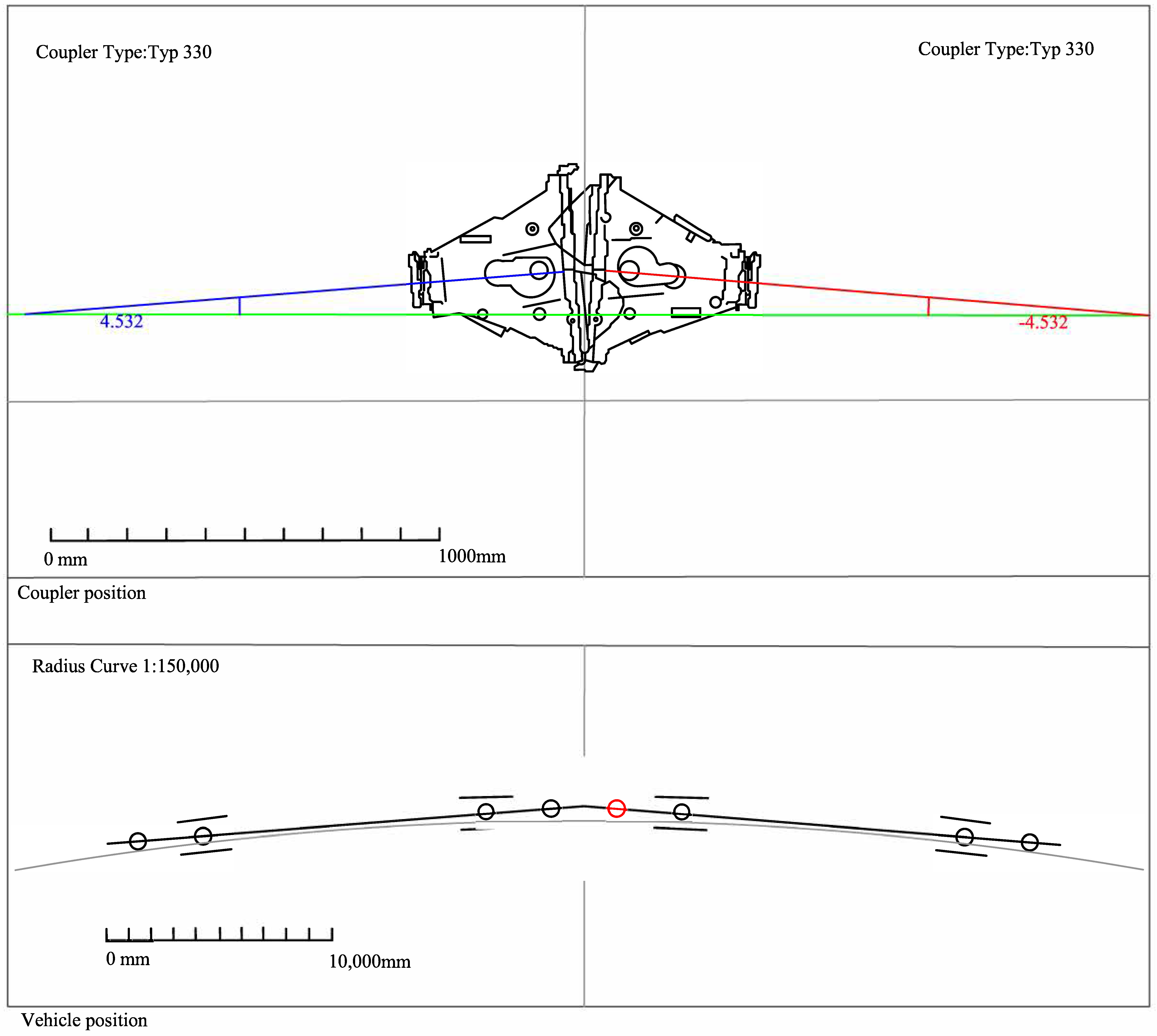
- We propose a new method to determine the coupler position, by calculating and analyzing the trajectory characteristics of the train under different line conditions, to verify whether the front-end couplers can be connected automatically and whether the coupler swing angle meets the connection requirements, to obtain the actual connection of the couplers on the horizontal curve.
- Our calculation method fully takes into account the effect of the lateral offset of the vehicle on the vehicle during the curve rescue linkage. Therefore, our algorithm is applicable to various line conditions, and it can accurately determine whether the hook swing angle meets the curve rescue linkage requirements when the train is under curve working conditions. Line calibration of Nanchang Rail Transit Line 3 through our calibration method, from the start of the line to date, there have been no accidents related to the rescue streak. In addition, after analyzing and judging by our calibration method under the actual line operation conditions of Nanchang Rail Transit Line 4, the parameters of some sections of the line were optimized and improved to ensure the safety of the trains in the curve rescue linkage.
- Our calculation method fully takes into account the influence of the lateral deflection of the vehicle on the coupling of the vehicle in curve rescue. Therefore, our algorithm is applicable to various line conditions and can accurately determine whether the coupler swing angle meets the requirements for rescue coupling when the train is in curve conditions.
2. Related Works
2.1. CAD 2D Geometric Drawing Simulation Analysis Method
2.2. Analytical Method
3. Preliminaries
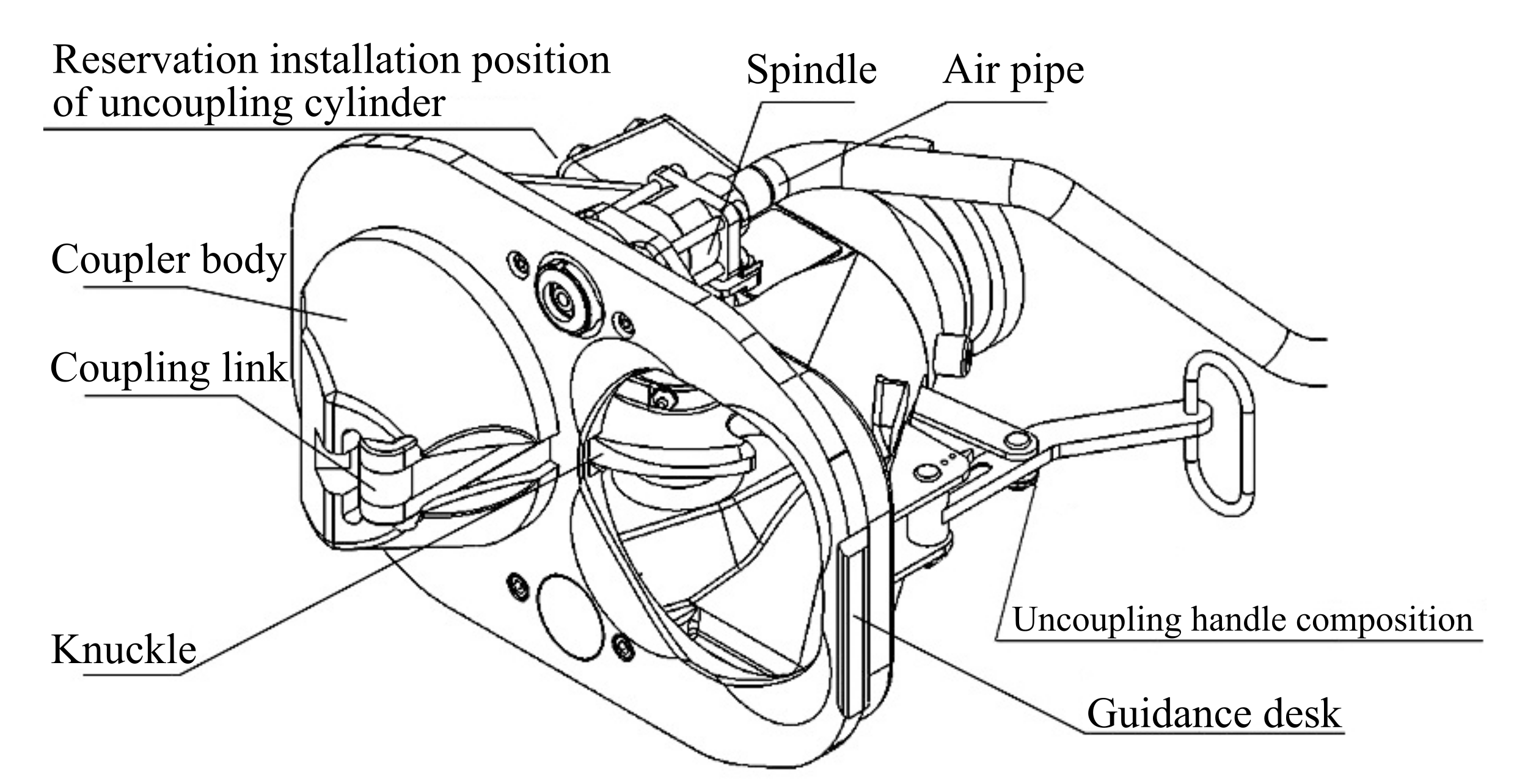
3.1. Structure and Principle
- Pending hooking. As shown in Figure 4a, at this time, the tension spring is in the maximum tension state, the coupling link is placed in the convex cone, and the connected composition is in the pending state.
- Continuous hooking. As shown in Figure 4b–d, the convex cone of the connecting hook extends into the concave cone of the opposing hook, and the knuckle on both sides pushes the opposing coupling link back to cause the knuckle to rotate, and as the hooks approach each other, the angle of the knuckle rotation increases, and under the action of the tension spring, the coupling link can enter the opposing knuckle to complete the connecting of the two couplers.
- Unhooking. Manually pull one side of the hook unhooking handle, drive the knuckle clockwise rotation, when the knuckle turned to a certain angle, the knuckle of this side of the hook, when the coupling link is in the unhooked state as shown in Figure 4e, then move one side of the hook body, you can complete the decomposition of the hook. When the two hooks are separated, the coupling link is reset due to the action of the tension spring, and the hook returns to the pending state.
3.2. Parameters
3.3. Vehicle Curve through Offset Calculation
3.3.1. Algorithm
3.3.2. Geometric Offset Calculation
3.3.3. Calculation of the Quasi-Static Offset ‘z’
3.3.4. Calculation of Special Terms ,
3.3.5. Lateral Offset of Vehicle through Curved Section
4. Proposed Method
4.1. Algorithm Analysis Steps
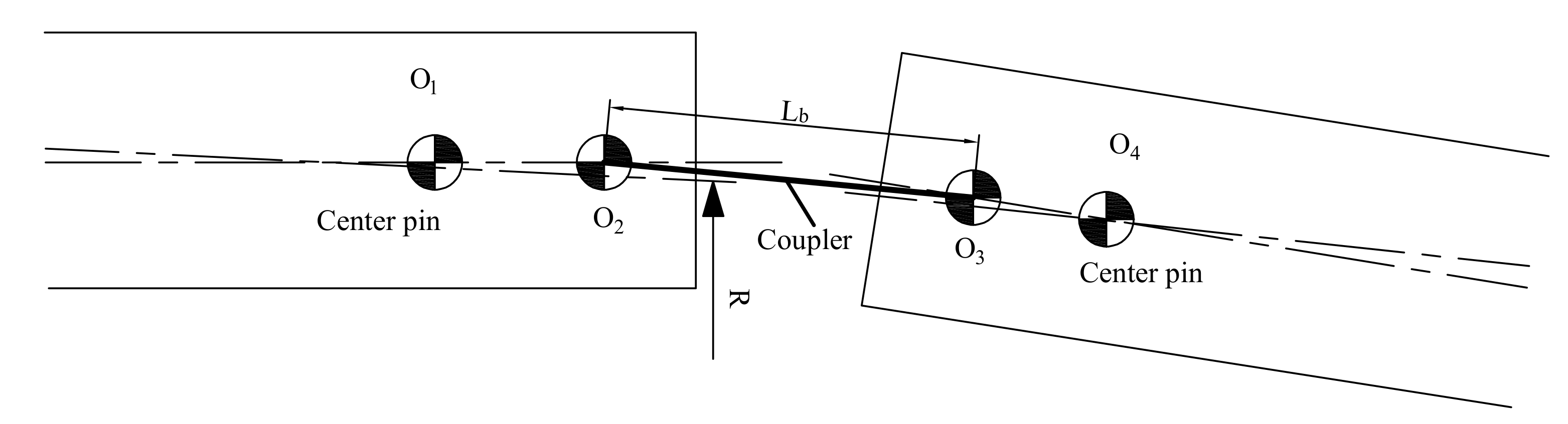
4.2. Determination Method of the Coupler Swing Angle under Horizontal Curve
4.3. Determination Method of Hook Position under Horizontal Curve
5. Analysis of Coupler Curve Connection under Different Working Conditions
5.1. Circular Curve Connection
5.1.1. Determination of Limiting Working Conditions
5.1.2. Feasibility Analysis of the Curve Rescue Linkage
5.2. Curve-Line Working Condition
5.2.1. Determination of Limiting Working Conditions
5.2.2. Feasibility Analysis of the Curve Rescue Linkage
5.3. S-Curve Connection
5.3.1. Determination of Limiting Working Conditions
5.3.2. Feasibility Analysis of the Curve Rescue Linkage
5.4. Data Summary
5.5. Train Manual Auxiliary Linkage
- A seat (pin or bolt with holes, etc.) is added under each anti-climber at the front of the train to hold the tension spring.
- When manual assistance is required to make a linkage on a curve, observe the relative positions of the hooks of the two cars and determine in which direction the hooks need to be rotated.
- Hang the tension spring at one end of the traction cable on the seat under the anti-climber; hang the tether at the other end of the cable on the strut of the protective tread of the hook head.
- Use the fasteners on the tether to shorten the length of the tow rope and rotate the hook to the desired position for attachment. At this point the tension spring will have some extension.
- After the hook is rotated to the required position for the linkage, the personnel on the ground for manual assistance leave the linkage area; the vehicle is moved for the linkage; the hook head also oscillates to a certain extent when the linkage is made, so that the length of the extension spring changes; the traction cable is removed after the linkage is completed.
5.6. Symmetry Analysis
5.6.1. Maximum Hook Turning Angle
- On the basis of the line of Nanchang Metro Line 4, the maximum hook turning angle of the same model of continuous vehicle through the horizontal curve has the largest value in the cure-line working condition, followed by the S-curve clamping straight line working condition, and finally the fixed circular curve working condition.
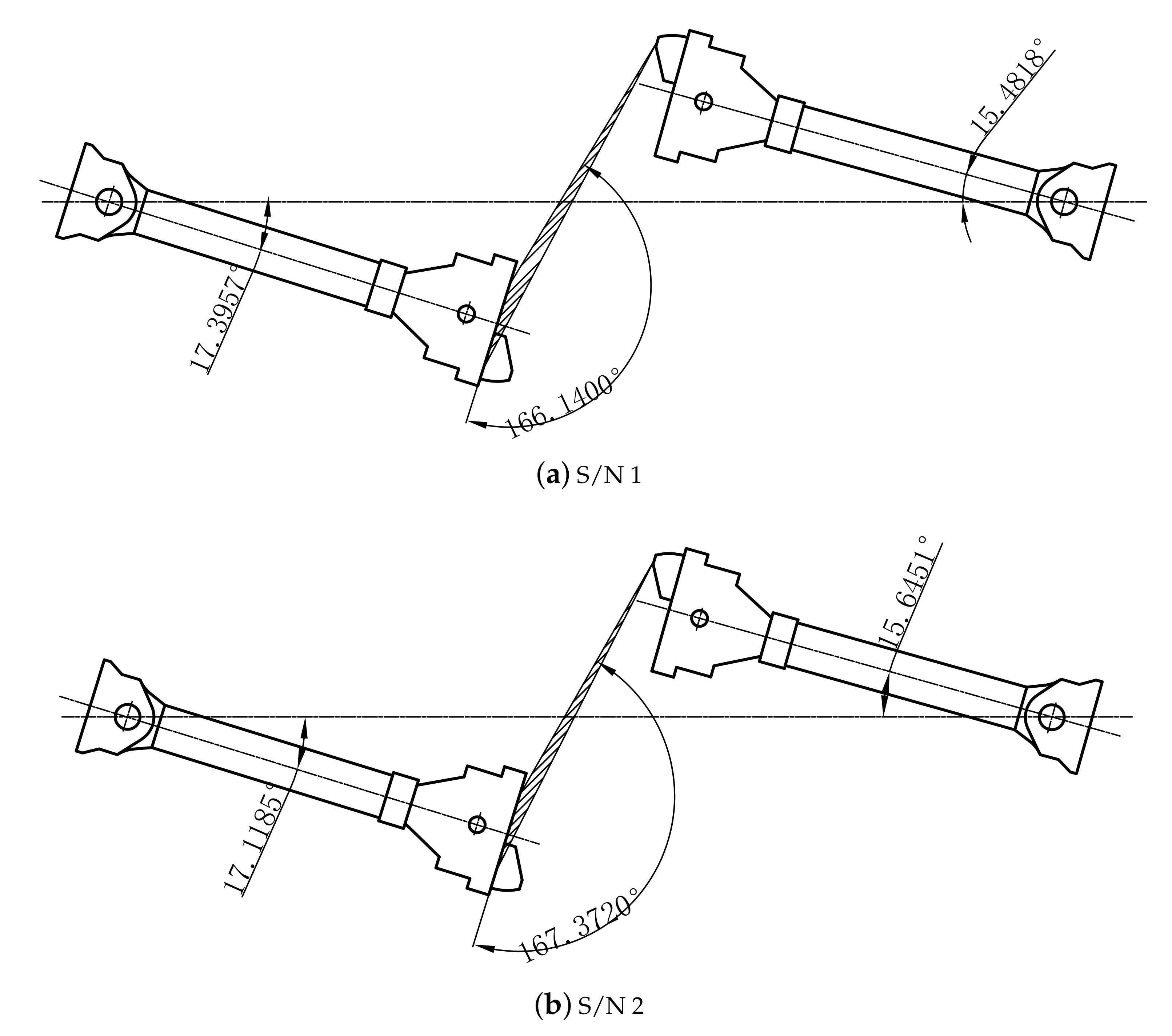
- The maximum hook angle derived from the simulation analysis algorithm using CAD 2D geometric mapping is slightly larger than the value derived from the graphical method, with a maximum relative error of 4.68% in the horizontal curve condition.
5.6.2. Combined Factor Comparison
6. Conclusions
Author Contributions
Funding
Institutional Review Board Statement
Informed Consent Statement
Data Availability Statement
Conflicts of Interest
References
- Pshinko, O.M.; Ursulyak, L.V.; Zhelieznov, K.I.; Shvets, A. To the problem of train running safety. IOP Conf. Ser. Mater. Sci. Eng. 2020, 985, 012014. [Google Scholar]
- Schumann, T. Increase of capacity on the Shinkansen high-speed line using virtual coupling. In Proceedings of the COMPRAIL 2016, Madrid, Spain, 19–21 July 2016. [Google Scholar]
- Todorov, G.; Kamberov, K.; Kralov, I.; Ignjatov, I. Influence of the contact roughness upon railway monobloc wheel acoustic behaviour on virtual prototyping approach. In AIP Conference Proceedings; AIP Publishing LLC: Sozopol, Bulgaria, 7 December 2017; Volume 1910, p. 020014. [Google Scholar]
- Magalhaes, H.; Madeira, J.; Ambrosio, J.; Pombo, J. Railway vehicle performance optimisation using virtual homologation. Veh. Syst. Dyn. 2016, 54, 1177–1207. [Google Scholar] [CrossRef]
- Bezin, Y.; Funfschilling, C.; Kraft, S.; Mazzola, L. Virtual testing environment tools for railway vehicle certification. Proc. Inst. Mech. Eng. Part F J. Rail Rapid Transit. 2015, 229, 755–769. [Google Scholar] [CrossRef] [Green Version]
- Kawasaki, K.; Seki, K. Development of a Radio Communication System Simulator for Railway Applications. Q. Rep. RTRI 2015, 56, 33–38. [Google Scholar] [CrossRef]
- Andrew, V.; Alexander, M.; Godyaev, I. 1F11 Designing a simulation model of a railway section using CAD layers (Operation management). Jpn. Soc. Mech. Eng. 2015. Available online: https://www.jstage.jst.go.jp/article/jsmestech/2015/0/2015__1F11-1_/_article.html (accessed on 19 September 2021).
- Wanchu, H. Theoretical analysis of vehicle geometry curve passage. Roll. Stock 1981, 8, 22–30. [Google Scholar]
- Shan, W.; Li, R. The Design and Checking Calculation of Coupled Cars in Negotiation of Curves. Roll. Stock 2004, 5, 5–8. [Google Scholar]
- Shvets, A.O. Analysis of the dynamics of freight cars with lateral displacement of the front bogie. Adv. Math. Model. Appl. 2021, 6, 45–58. [Google Scholar]
- Zhang, G.; Shen, G.; Zhang, Y. The Dynamic Simulation Analysis of the Interference of the Adjacent Car-bodies and Bogies for the Dual-Hinged Train. China Railw. 2005, 4, 1–3. [Google Scholar]
- Wang, W.; Mi, C. Parameterized calculation of geometry curve negotiation of locomotive. Railw. Locomot. Mot. Car 2007, 11, 17–20. [Google Scholar]
- Luke, W. Calculation of curving of locomotives and vehicles by introducing the conception of equivalent radius of curve. Electr. Locomot. Mass Transit Veh. 2016, 6, 89–92. [Google Scholar]
- Zhang, K.; Meng, L. Analysis of the curve passing capacity of the vehicle end connection device of rolling stock. China-High-Tech Enterp. 2013, 13, 103–106. [Google Scholar]
- Li, B.; Li, D.; Ren, X.; Xu, D. Analysis on rescue of B-type metro trains connected in curve. China Railw. 2016, 06, 89–92. [Google Scholar]
- Wang, L.; Min, Y.; Liu, X. Analysis on the Calculation Method and Result- validity of Coupling Simulations for Heavy Load Locomotive. Railw. Locomot. Car 2016, 16, 48–68. [Google Scholar]
- Zou, R.; Ma, W.; Luo, S. Coupling stability of couplers between locomotive and vehicle. J. Traffic Transp. Eng. 2016, 16, 48–54. [Google Scholar]
- Zhu, J. Analysis and Discussion on the Causes of the Failure of Fully Automatic Coupler. Electr. Locomot. Mass Transit Veh. 2017, 40, 90–92. [Google Scholar]
- Ozerov, M.A.; Li, Q. Check of connected vehicles passing through the curve section. Foreign Roll. Stock 1966, 4, 50–54. [Google Scholar]
- Zhang, P.M.; Zhang, S.H.; Jia, K. Coupling analysis on a tight-lock coupler for subway vehicle. Mach. Des. Manuf. 2011, 6, 38–40. [Google Scholar]
- Ouyang, S.; Peng, Y.; Gao, W. Discussion of the Way to Detect the State of Coupling Structure of Couplers. Roll. Stock 2011, 49, 24–28. [Google Scholar]
- Song, W. Study on the Distance Between Turnout and Horizontal Curve of Rail Transit in City Region. J. ECJTU 2018, 35, 22–26. [Google Scholar]
- Li, C. Study on Minimum Curve Radius for Railway Vehicles. Railw. Stand Des. 2016, 60, 19–24. [Google Scholar]
- Bing, L.; Ai, M.; Pan, H. Analysis of the Maximum Deflection Angle of Coupler When Railway Cars Passing Horizontal Curve. Railw. Qual. Des. 2014, 42, 3–8. [Google Scholar]
- UIC 505-1. Railway Transport Stock-Rolling Stock Construction Ganges. 1977. Available online: https://www.docin.com/p-349898773.html (accessed on 20 September 2021).
- UIC CODE 505-4. Effects of the Application of the Kinematic Gauge Defined in the 505 Series of Leafletson the Positioning of Structures in Relation to the Tracks and of the Tracks in Relation to Each Other, 4th ed.; 2007; Available online: https://www.docin.com/p-349898824.html (accessed on 20 September 2021).
- Kampczyk, A. Magnetic-measuring square in the measurement of the circular curve of rail transport tracks. Sensors 2020, 20, 560. [Google Scholar] [CrossRef] [Green Version]
- Kampczyk, A. Measurement of the geometric center of a turnout for the safety of railway infrastructure using MMS and total station. Sensors 2018, 20, 4467. [Google Scholar] [CrossRef] [PubMed]
- Gu, Y.; Liu, L.; Mou, X. Main parts of the couplers for metro vehicles and their selection. Locomot. Roll. Stock Technol. 2018, 2, 34–37. [Google Scholar]
- Xu, Z.; Ma, W.; Wu, Q.; Luo, S. Analysis of the rotation angle of a coupler used on heavy haul locomotives. Proc. Inst. Mech. Eng. Part F 2014, 228, 835–844. [Google Scholar] [CrossRef]
- Luo, R.; Gan, F.; Teng, W.; Cong, R. Calculation of coupling vehicles geometrically passing through curves. Electr. Locomot. Mass Transit Veh. 2013, 36, 16–18. [Google Scholar]
- Jin, X.; Zhang, H.; Shuai, G.; Kuang, X.; Lin, F. Research on Simulation Calculation of Coupler Swing Angle During Rail Vehicles Passing Curve. J. ECJTU 2019, 36, 19–24. [Google Scholar]
- Railway Application Facilities Automatic Coupler Performance Requirements, Dedicated Interface Geometry. EN16019-2014. 2014. Available online: https://www.doc88.com/p-5783803430033.html (accessed on 15 September 2021).
- Feng, G. Analysis of the position of the center line of the coupler connection. Roll. Stock 1986, 11, 33–34. [Google Scholar]


| Serial Number | Parameter | Initial Value (mm) | Remarks |
|---|---|---|---|
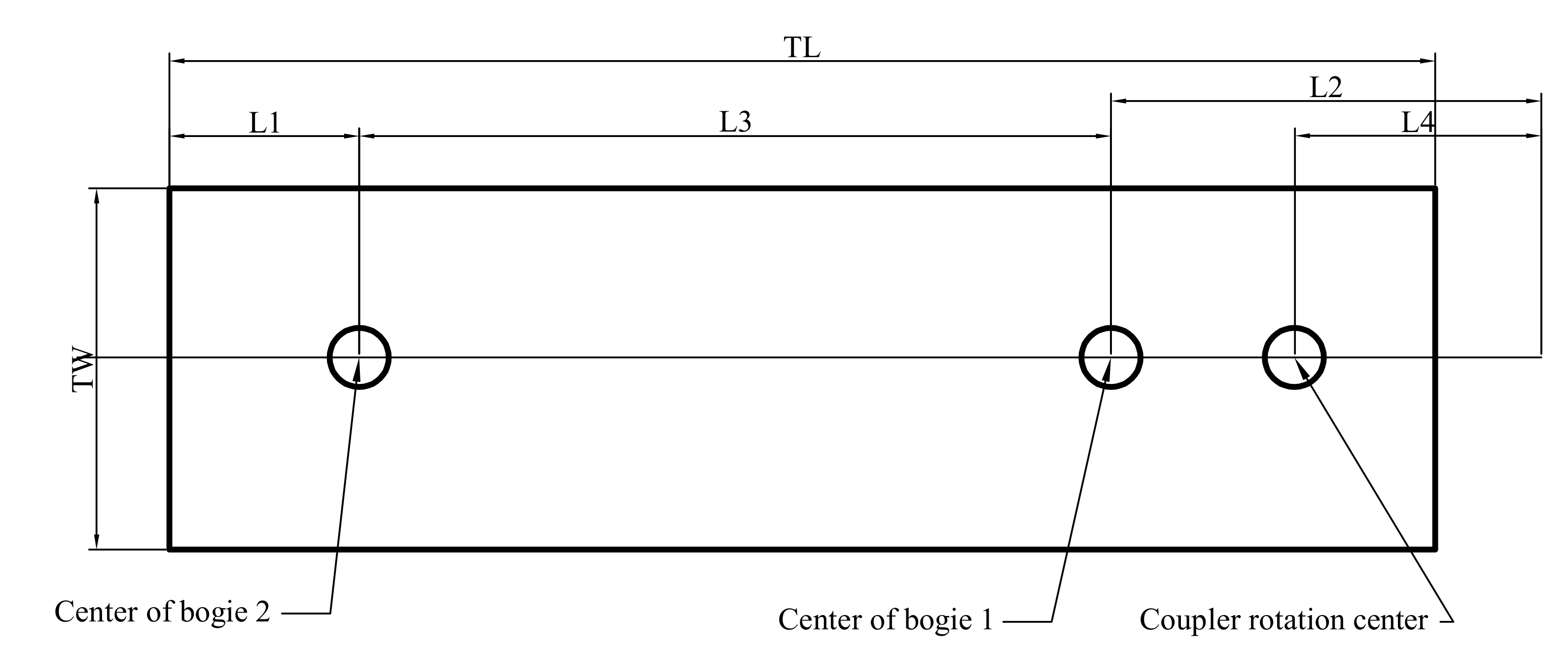
| 1 | L | 2100 | Distance from the center of the 2-position bogie to the vehicle end |
| 2 | L2 | 2339 | The distance from the center of a bogie to the center of rotation of the coupler |
| 3 | L3 | 12,600 | Distance from 1 bogie center to 2 bogie center |
| 4 | L4 | 1225 | Distance from coupler rotation center to even noodle |
| 5 | TL | 19,000 | Vehicle length |
| 6 | TW | 2800 | Vehicle width |
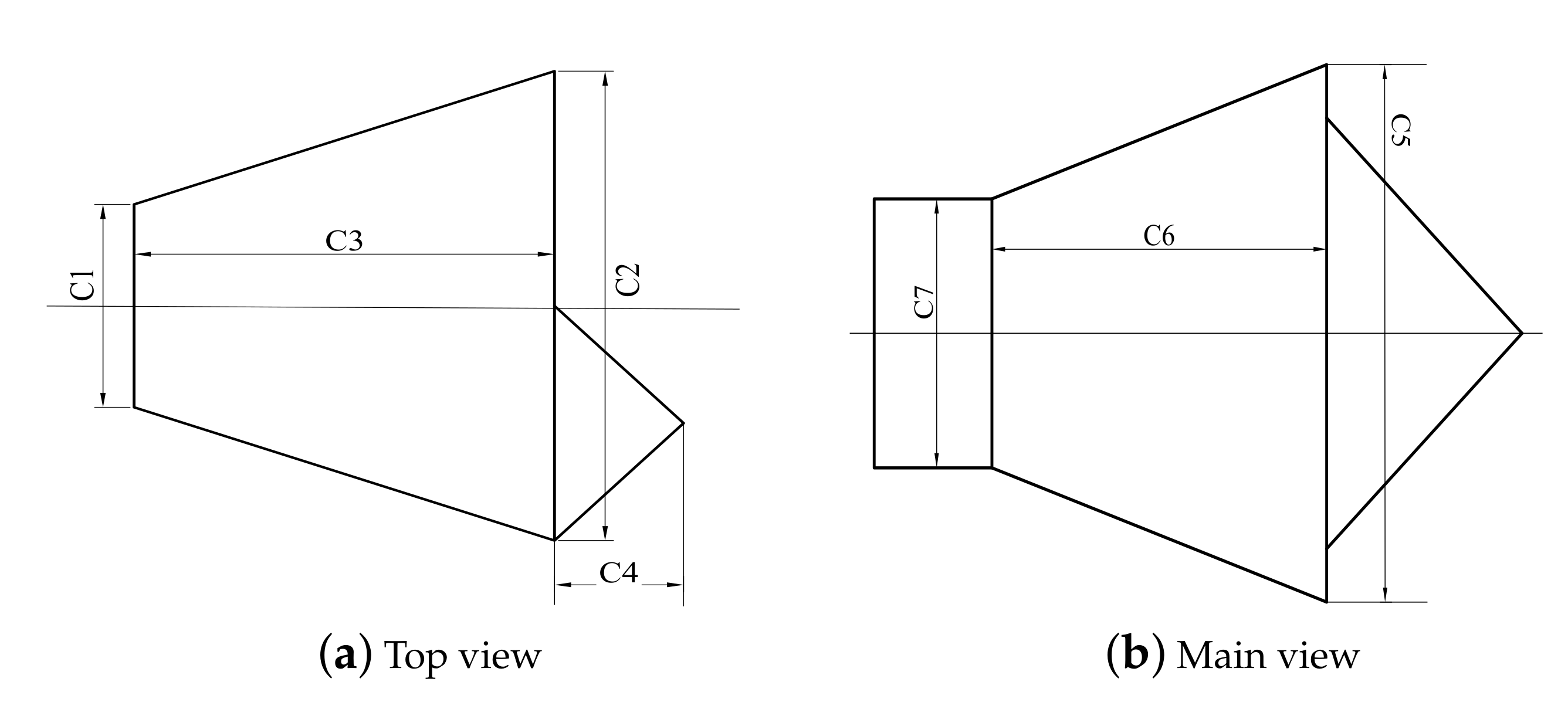
| 7 | C1 | 140 | Width of hook head and tail |
| 8 | C2 | 480 | Hook head width |
| 9 | C3 | 280 | Hook length |
| 10 | C4 | 115 | Length of hook head convex cone |
| 11 | C5 | 297 | Height of hook head convex cone (top view) |
| 12 | C6 | 150 | Hook length |
| 13 | C7 | 100 | Width of hook head and tail |
| 14 | W1 | 170 | Horizontal left distance of hook head connecting position |
| 15 | W2 | 170 | The horizontal right distance of the hook head connecting position |
| 16 | W3 | 90 | The distance from the upper side of the hook head connecting position |
| 17 | W4 | 90 | The distance from the lower side of the hook position |
| S/N | Coupler Swing Angle (°) | Center Pin Lateral Offset (mm) | ||||
|---|---|---|---|---|---|---|
| No.1 Vehicle | No.2 Vehicle | No.1 Coupler of No.1 Vehicle | No.2 Coupler of No.1 Vehicle | No.1 Coupler of No.2 Vehicle | No.2 Coupler of No.2 Vehicle | |
| 1 | 5.0384 | 8.4963 | 75 | −75 | 75 | −75 |
| 2 | 3.346 | 7.7047 | −75 | 75 | −75 | 75 |
| S/N | Position | Coupler Swing Angle (°) | Center Pin Lateral Offset (mm) | ||||
|---|---|---|---|---|---|---|---|
| No.1 Vehicle | No.2 Vehicle | No.1 Coupler of No.1 Vehicle | No.2 Coupler of No.1 Vehicle | No.1 Coupler of No.2 Vehicle | No.2 Coupler of No.2 Vehicle | ||
| 1 | 1.0 | 17.3957 | 15.4818 | −83.5 | 83.5 | −83.5 | 83.5 |
| 2 | −2.5 | 17.1185 | 15.6451 | 83.5 | 83.5 | −83.5 | 83.5 |
| S/N | Position | Coupler Swing Angle (°) | Center Pin Lateral Offset (mm) | ||||
|---|---|---|---|---|---|---|---|
| No.1 Vehicle | No.2 Vehicle | No.1 Coupler of No.1 Vehicle | No.2 Coupler of No.1 Vehicle | No.1 Coupler of No.2 Vehicle | No.2 Coupler of No.2 Vehicle | ||
| 1 | 42.671 | 10.132 | 6.975 | −99 | 99 | 99 | −99 |
| 2 | 4.0 | 6.886 | 10.146 | −99 | −99 | 99 | 99 |
| The Position of the Train on the Actual Line | |||
|---|---|---|---|
| Left Line of the Main Line at 445.777 km∼759.731 km | The Right Line of the Main Line 444.175 km∼754.205 km | Wangcheng Vehicle Section | |
| Maximum angle | 152.1074° | 167.3720° | 150.4819° |
| Realization Method | Efficiency | Economical | Accuracy | Stability | |
|---|---|---|---|---|---|
| CAD 2D geometric drawing method | Manual drawing | Low | Low | High | Unstable |
| Voytek’s algorithm | Computer programs | High | High | Low | Stable |
| Algorithm of this paper | Computer programs | High | High | Medium | Stable |
Publisher’s Note: MDPI stays neutral with regard to jurisdictional claims in published maps and institutional affiliations. |
© 2021 by the authors. Licensee MDPI, Basel, Switzerland. This article is an open access article distributed under the terms and conditions of the Creative Commons Attribution (CC BY) license (https://creativecommons.org/licenses/by/4.0/).
Share and Cite
Zhang, H.; Zhang, C.; Lin, F.; Wang, X.; Fu, G. Research on Simulation Calculation of the Safety of Tight-Lock Coupler Curve Coupling. Symmetry 2021, 13, 1997. https://doi.org/10.3390/sym13111997
Zhang H, Zhang C, Lin F, Wang X, Fu G. Research on Simulation Calculation of the Safety of Tight-Lock Coupler Curve Coupling. Symmetry. 2021; 13(11):1997. https://doi.org/10.3390/sym13111997
Chicago/Turabian StyleZhang, Hai, Chenyu Zhang, Fengtao Lin, Xiugang Wang, and Gengzhe Fu. 2021. "Research on Simulation Calculation of the Safety of Tight-Lock Coupler Curve Coupling" Symmetry 13, no. 11: 1997. https://doi.org/10.3390/sym13111997
APA StyleZhang, H., Zhang, C., Lin, F., Wang, X., & Fu, G. (2021). Research on Simulation Calculation of the Safety of Tight-Lock Coupler Curve Coupling. Symmetry, 13(11), 1997. https://doi.org/10.3390/sym13111997