Electroactive Textile Actuators for Breathability Control and Thermal Regulation Devices

 ,
,  ,
, 
Abstract

1. Introduction
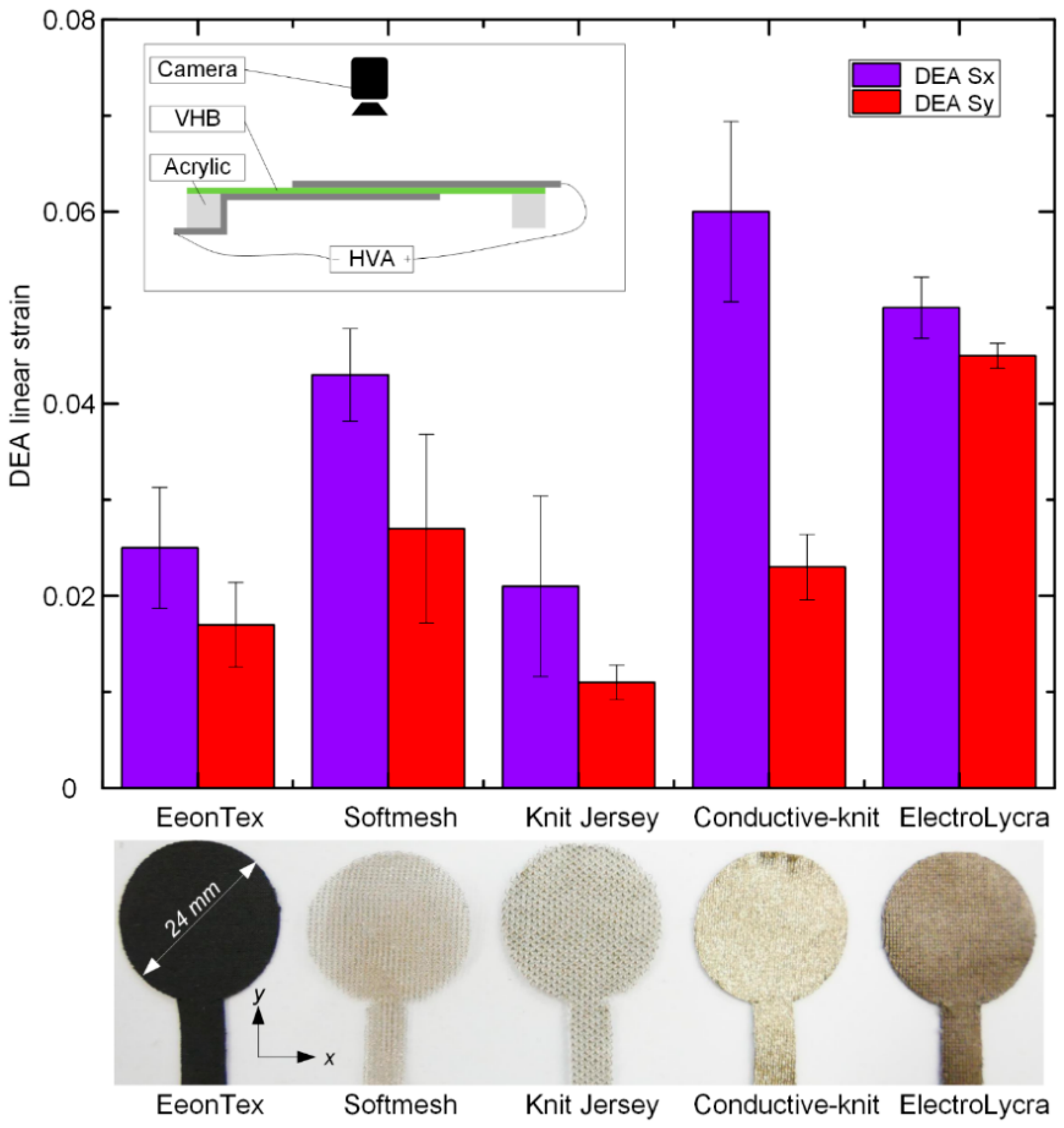
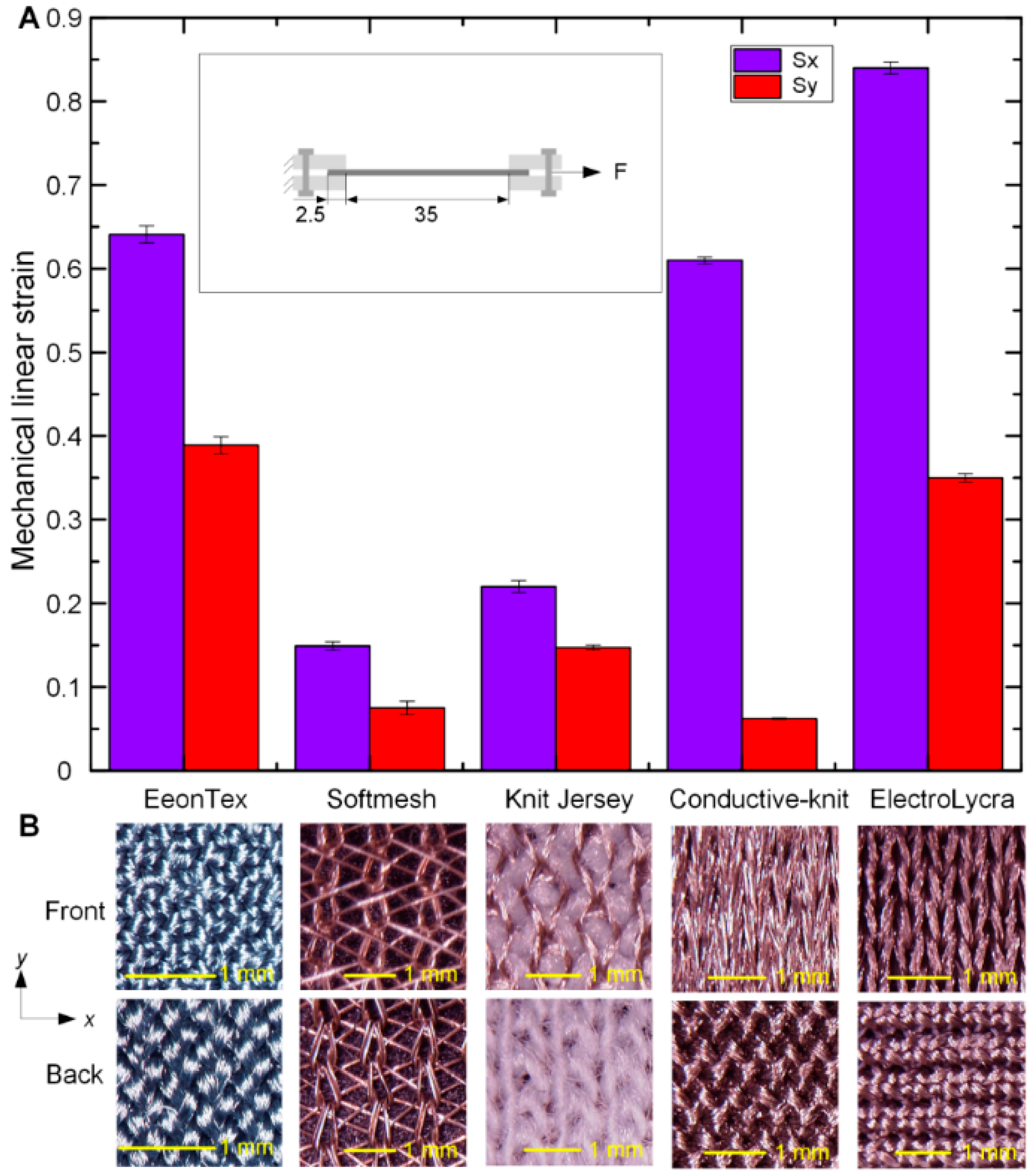
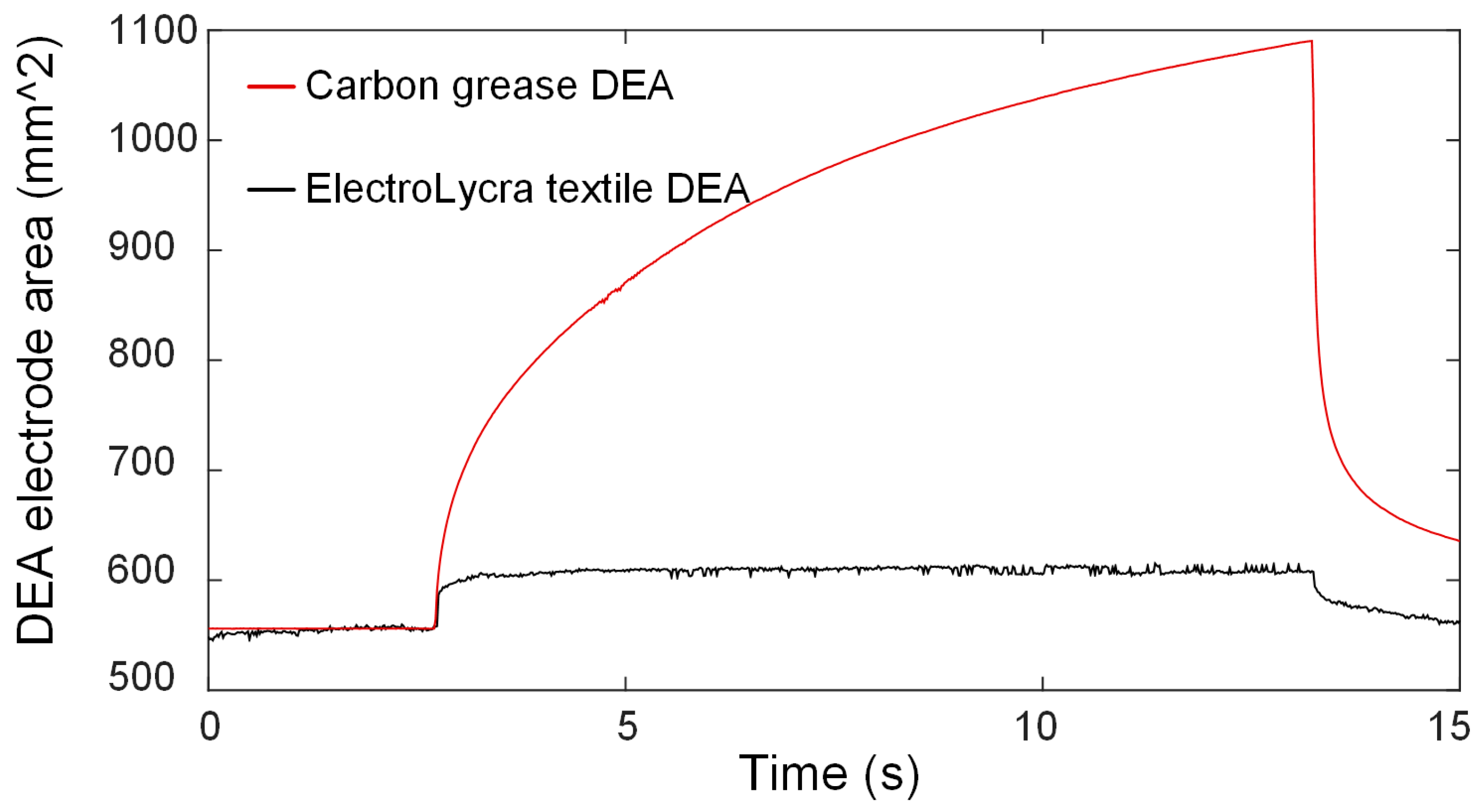
2. Conductive Textile Dielectric Elastomer Actuation
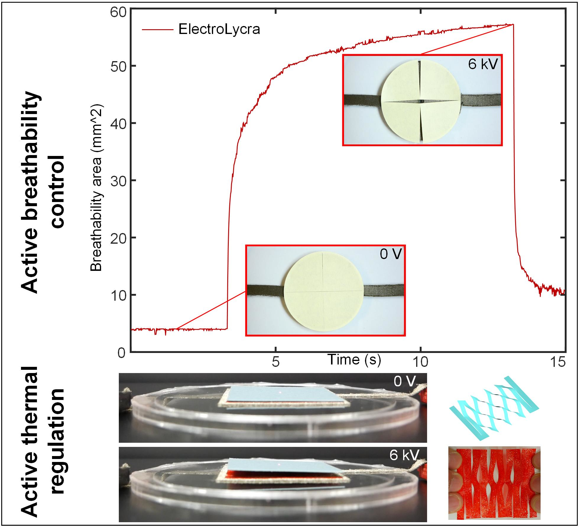
3. DEA Driven Breathability and Thermal Control Devices
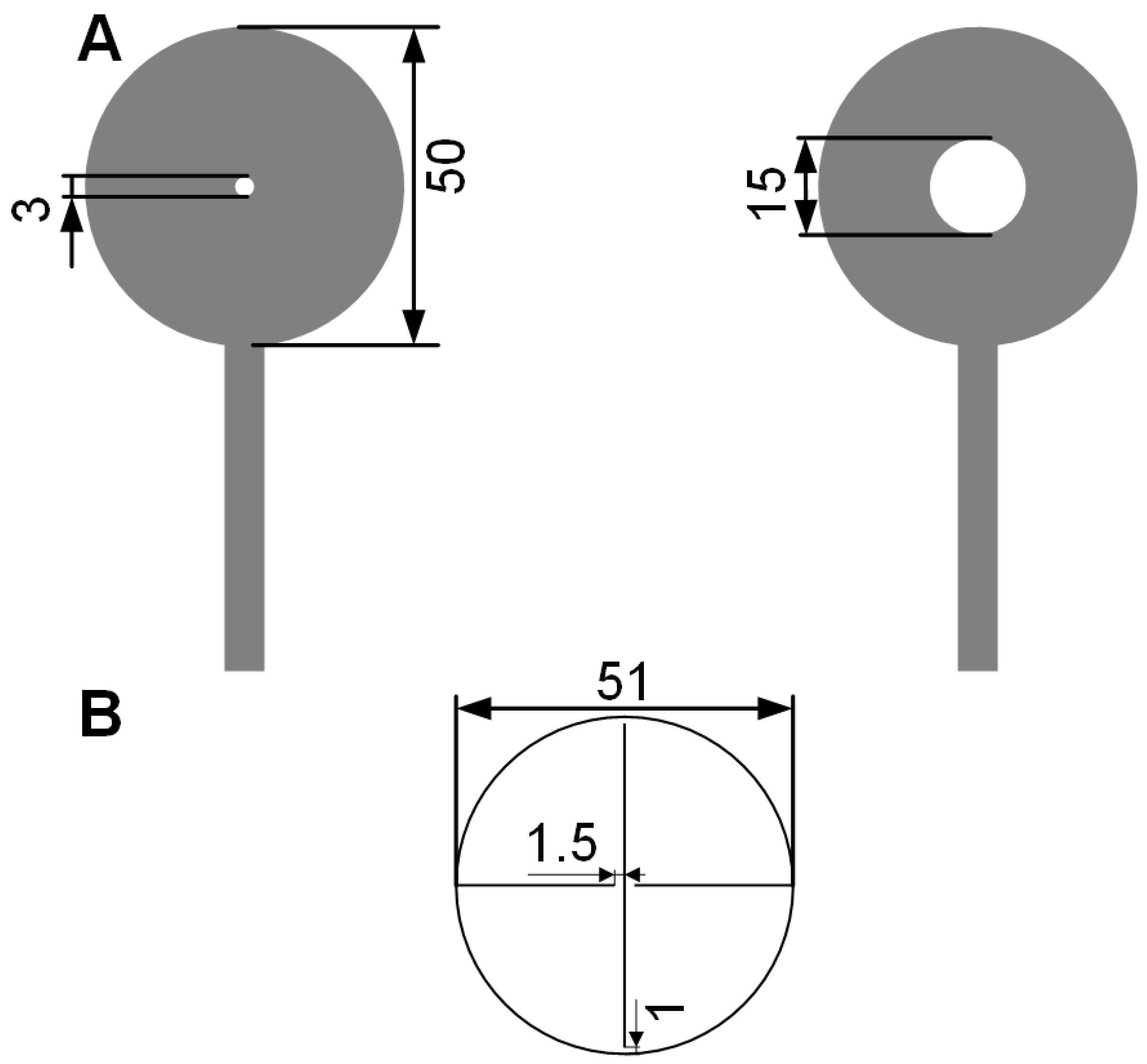
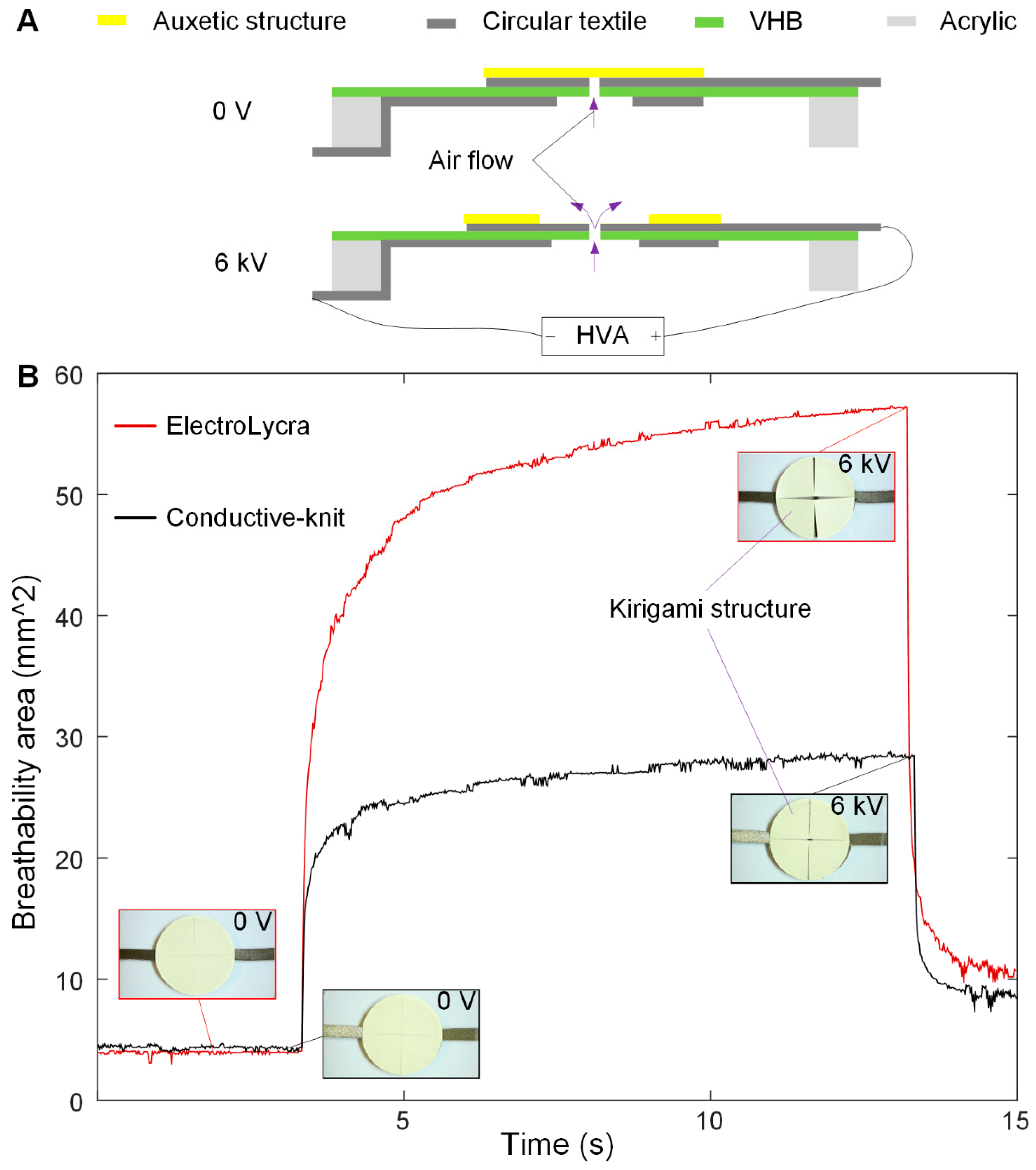
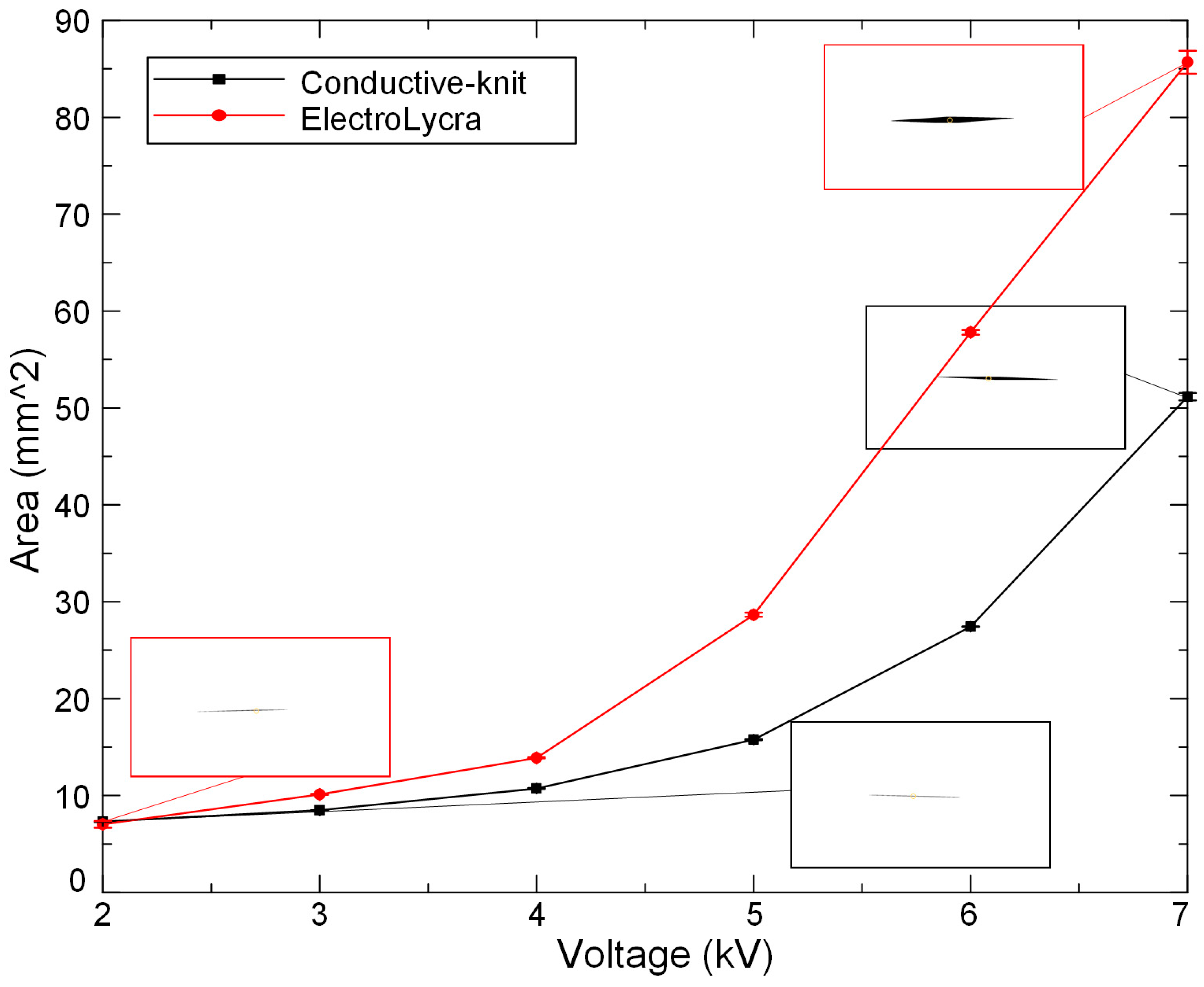
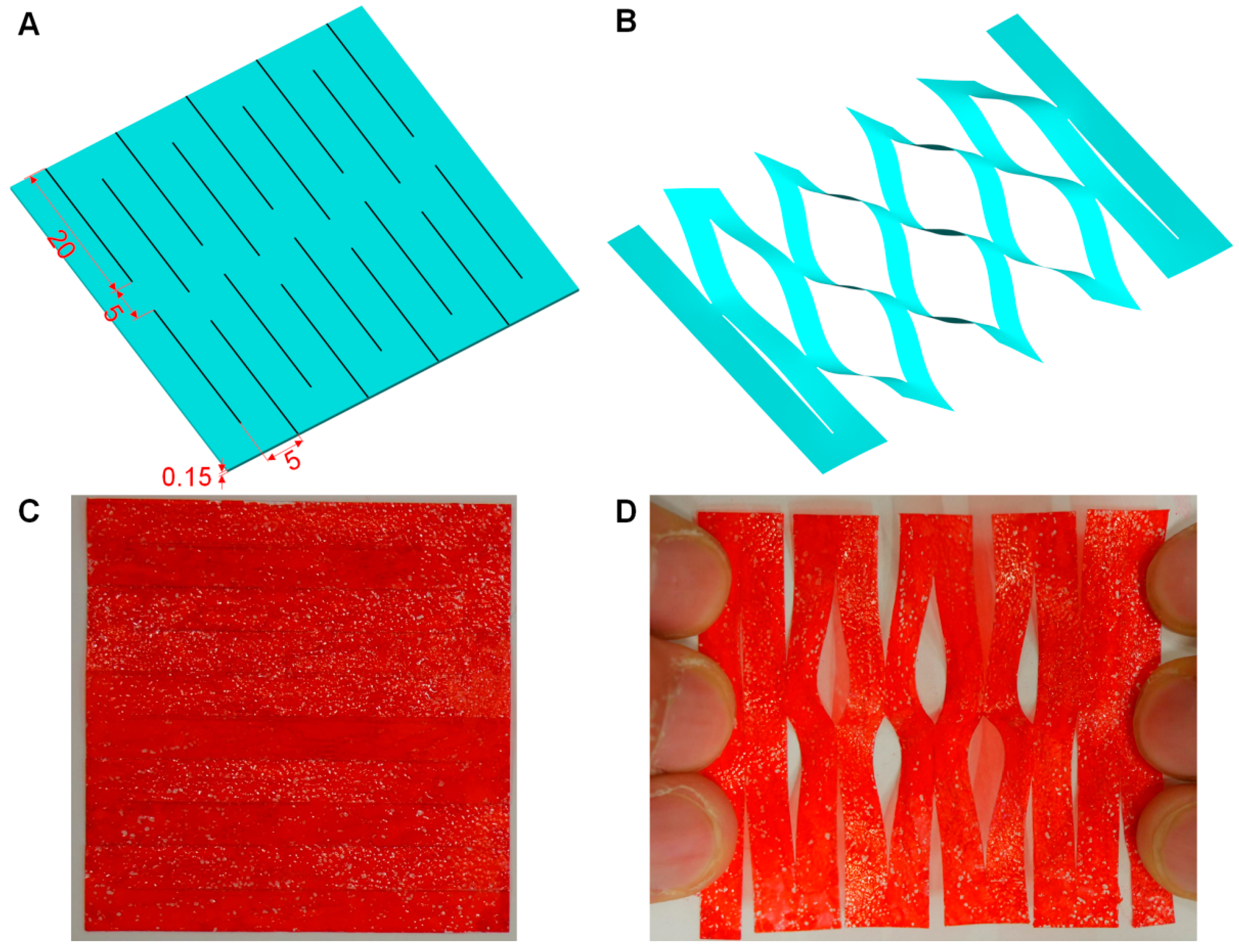
3.1. 2D Textile Breathability Control Device
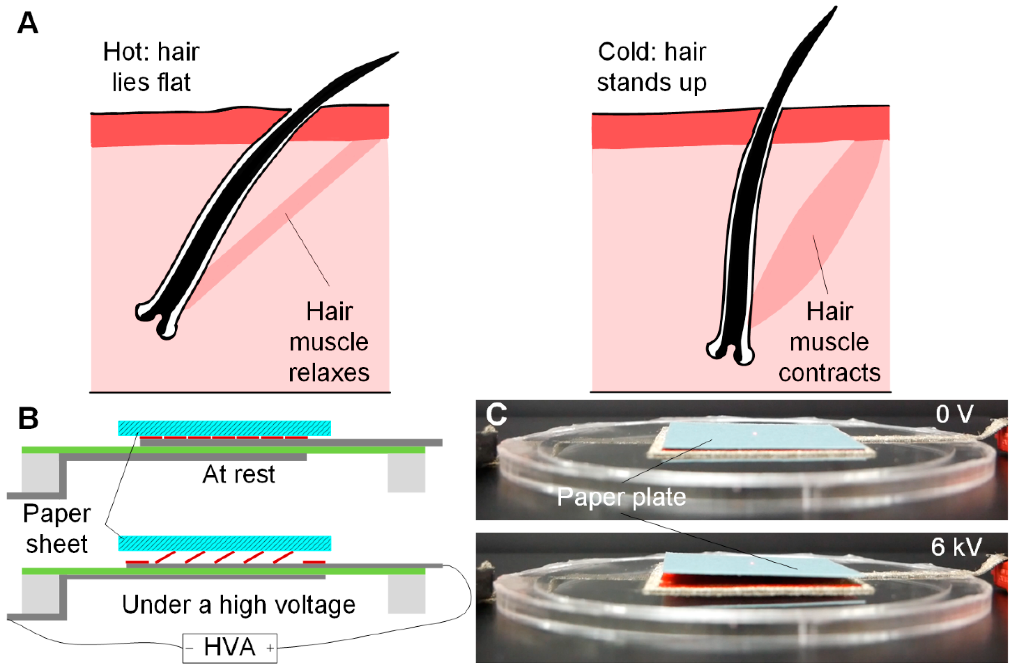
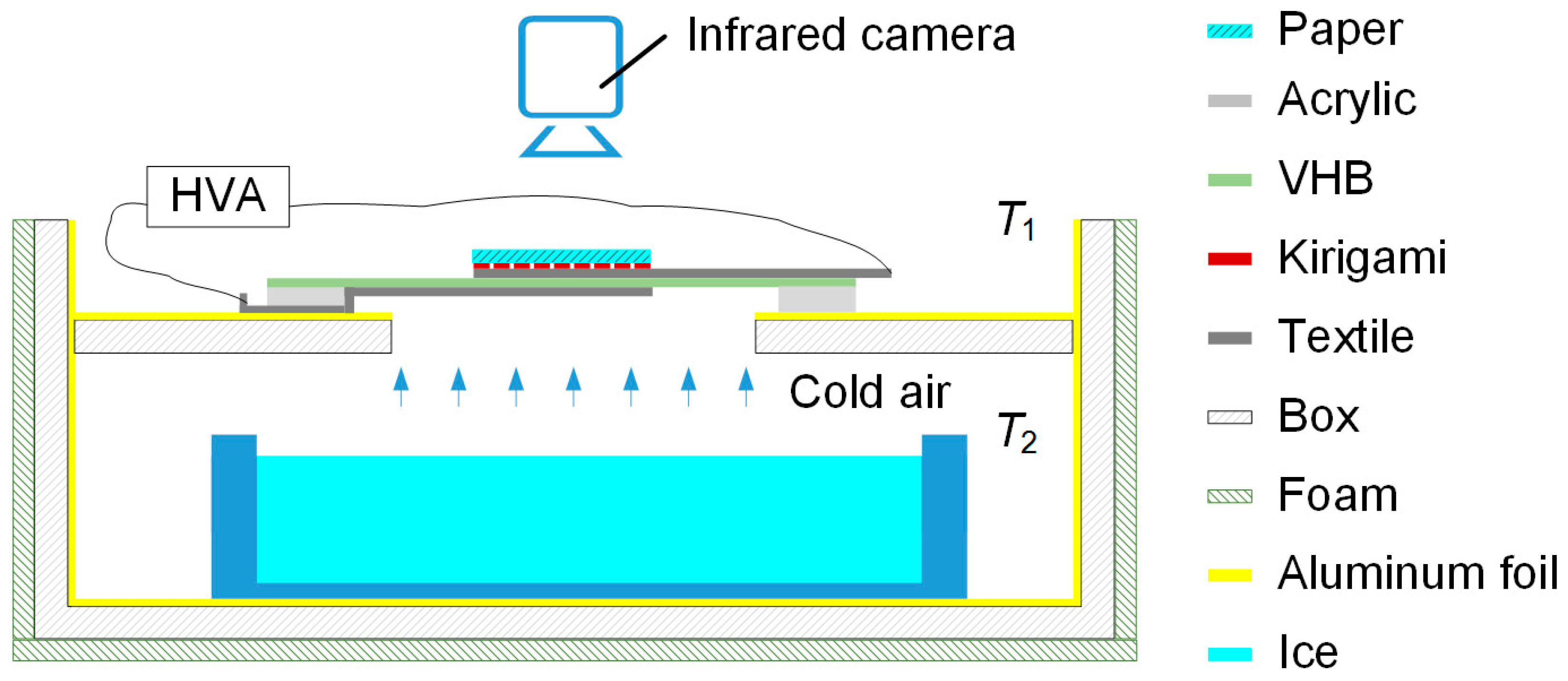
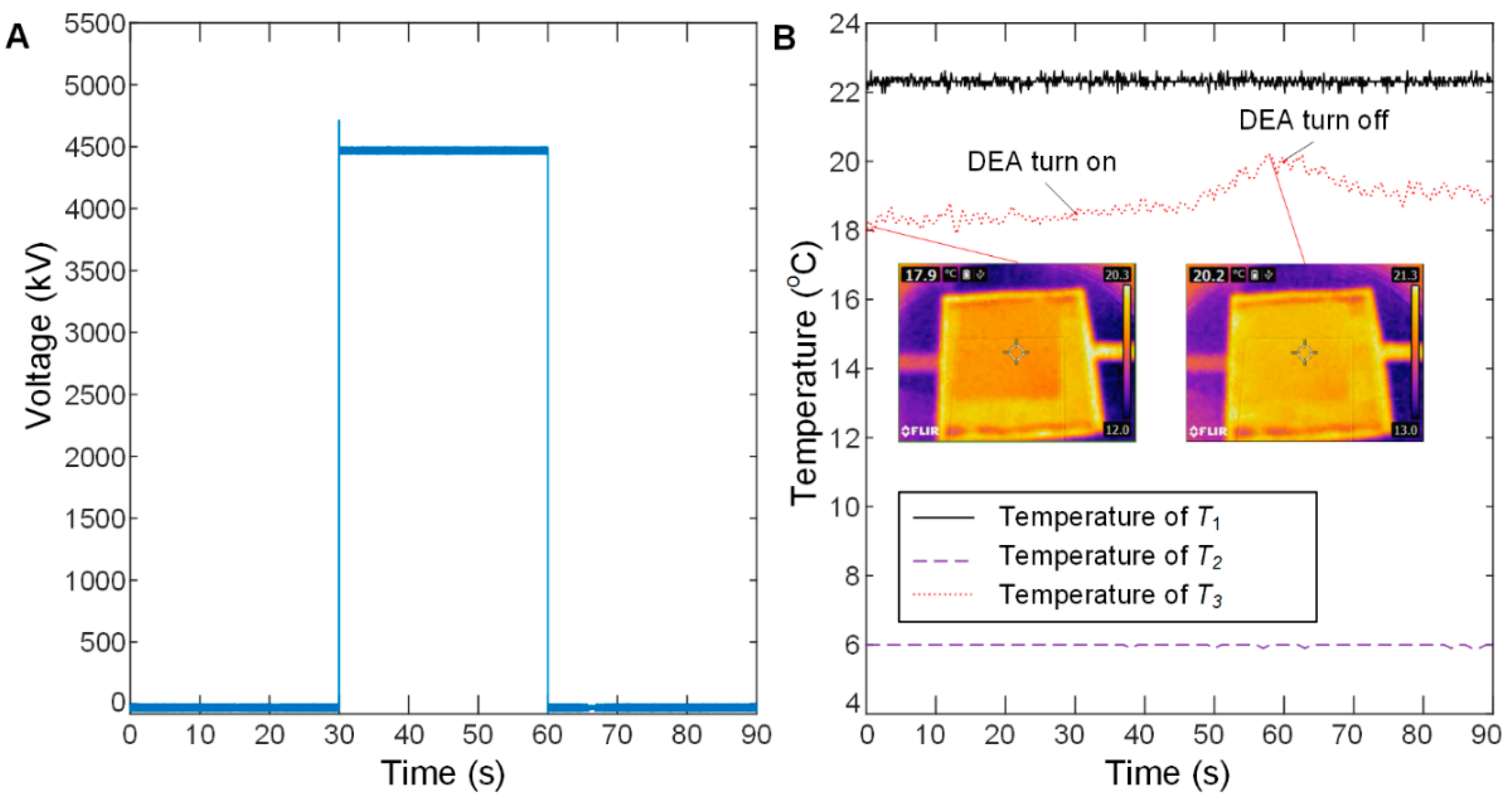
3.2. 3D Kirigami Thermal Regulation Device
4. Conclusions and Future Work
Supplementary Materials
Author Contributions
Funding
Conflicts of Interest
References
- Ilievski, F.; Mazzeo, A.D.; Shepherd, R.F.; Chen, X.; Whitesides, G.M. Soft robotics for chemists. Angew. Chem. 2011, 50, 1890–1895. [Google Scholar] [CrossRef]
- Whitesides, G.M. Soft robotics. Angew. Chem. 2018, 57, 4258–4273. [Google Scholar] [CrossRef]
- Majidi, C. Soft robotics: A perspective-Current trends and prospects for the future. Soft Robot. 2013, 1, 5–11. [Google Scholar] [CrossRef]
- Rus, D.; Tolley, M.T. Design, fabrication and control of soft robots. Nature 2015, 521, 467–475. [Google Scholar] [CrossRef]
- Laschi, C.; Mazzolai, B.; Cianchetti, M. Soft robotics: Technologies and systems pushing the boundaries of robot abilities. Sci. Robot. 2016, 1, 1–12. [Google Scholar] [CrossRef]
- Xie, R.Z.; Su, M.J.; Zhang, Y.H.; Li, M.J.; Zhu, H.F.; Guan, Y.S. PISRob: A pneumatic soft robot for locomoting like an inchworm. In Proceedings of the 2018 IEEE International Conference on Robotics and Automation (ICRA), Brisbane, Australia, 21–26 May 2018; pp. 3448–3453. [Google Scholar]
- Huang, H.M.; Lin, J.H.; Wu, L.Y.; Fang, B.; Sun, F.C. Optimal control scheme for pneumatic soft actuator under comparison of proportional and PWM-solenoid valves. Photonic Netw. Commun. 2019, 37, 153–163. [Google Scholar] [CrossRef]
- Shintake, J.; Rosset, S.; Schubert, B.; Floreano, D.; Shea, H. Versatile soft grippers with intrinsic electroadhesion based on multifunctional polymer actuators. Adv. Mater. 2016, 28, 231–238. [Google Scholar] [CrossRef]
- Terryn, S.; Brancart, J.; Lefeber, D.; Assche, G.V.; Vanderborght, B. Self-healing soft pneumatic robots. Sci. Robot. 2017, 1, 1–13. [Google Scholar] [CrossRef]
- Hines, L.; Petersen, K.; Lum, G.Z.; Sitti, M. Soft actuators for small-scale robotics. Adv. Mater. 2016, 29, 1603483. [Google Scholar] [CrossRef]
- Pelrine, R.; Kornbluh, R.; Pei, Q.B.; Joseph, J. High-speed electrically actuated elastomers with strain greater than 100%. Science 2000, 287, 836–840. [Google Scholar] [CrossRef]
- Rosset, S.; Shea, H.R. Small, fast, and tough: Shrinking down integrated elastomer transducers. Appl. Phys. Rev. 2016, 3, 031105. [Google Scholar] [CrossRef]
- Carpi, F.; Frediani, G.; Turco, S.; Rossi, D. Bioinspired tunable lens with muscle-like electroactive elastomers. Adv. Funct. Mater. 2011, 21, 4152–4158. [Google Scholar] [CrossRef]
- Conn, A.T.; Rossiter, J. Towards holonomic electro-elastomer actuators with six degrees of freedom. Smart Mater. Struct. 2012, 21, 035012. [Google Scholar] [CrossRef]
- Liu, Y.; Gao, M.; Mei, S.F.; Han, Y.T.; Liu, J. Ultra-compliant liquid metal electrodes with in-plane self-healing capability for dielectric elastomer actuators. Appl. Phys. Lett. 2013, 103, 064101. [Google Scholar] [CrossRef]
- Zhang, C.; Sun, W.J.; Liu, L.; Li, B.; Li, D. Electromechanical deformation of conical dielectric elastomer actuator with hydrogel electrodes. J. Appl. Phys. 2016, 119, 094108. [Google Scholar] [CrossRef]
- Rogers, J.A.; Someya, T.; Huang, Y. Materials and mechanics for stretchable electronics. Science 2010, 327, 1603–1607. [Google Scholar] [CrossRef]
- Liu, C.; Liu, J.; Ning, X.; Chen, S.; Liu, Z.; Jiang, S.; Miao, D. The effect of polydopamine on an ag-coated polypropylene nonwoven fabric. Polymers 2019, 11, 627. [Google Scholar] [CrossRef]
- Guo, J.L.; Xiang, C.Q.; Helps, T.; Taghavi, M.; Rossiter, J. Electroactive textile actuators for wearable and soft robots. In Proceedings of the 2018 IEEE International Conference on Soft Robotics (RoboSoft), Livorno, Italy, 24–28 April 2018; pp. 339–343. [Google Scholar]
- Allen, D.P.; Farmer, S.E.; Gregg, R.D.; Voit, W. Stretchable conductive fabric simplifies manufacturing of low-resistance dielectric-elastomer-system electrodes. In Proceedings of the Electroactive Polymer Actuators and Devices (EAPAD), Denver, CO, USA, 5–8 March 2018; p. 1059412. [Google Scholar]
- Wang, L.H.; Hayakawa, T.; Ishikawa, M. Dielectric-elastomer-based fabrication method for varifocal microlens array. Opt. Express 2017, 25, 31708–31717. [Google Scholar] [CrossRef]
- Maziz, A.; Concas, A.; Khaldi, A.; Stålhand, J.; Persson, N.K.; Jager, W.H. Knitting and weaving artificial muscles. Sci. Adv. 2017, 3, e1600327. [Google Scholar] [CrossRef]
- WIKIPEDIA, Breathability. Available online: https://en.wikipedia.org/wiki/Breathability (accessed on 10 September 2018).
- Zhang, X.A.; Yu, S.; Xu, B.; Li, M.; Peng, Z.; Wang, Y.; Deng, S.; Wu, X.; Wu, Z.; Ouyang, M.; et al. Dynamic gating of infrared radiation in a textile. Science 2019, 363, 619–623. [Google Scholar] [CrossRef]
- Brodribb, T.J.; McAdam, S.A. Passive origins of stomatal control in vascular plants. Science 2011, 331, 582–585. [Google Scholar] [CrossRef]
- WIKIPEDIA, Origami. Available online: https://en.wikipedia.org/wiki/Origami (accessed on 10 September 2018).
- Sun, R.J.; Zhang, B.; Yang, L.; Zhang, W.J.; Farrow, I.; Scarpa, F.; Rossiter, J. Kirigami stretchable strain sensors with enhanced piezoelectricity induced by topological electrodes. Appl. Phys. Lett. 2018, 112, 251904. [Google Scholar] [CrossRef]
- Rafsanjani, A.; Zhang, Y.; Liu, B.Y.; Rubinstein, S.M.; Bertoldi, K. Kirigami skins make a simple soft actuator crawl. Sci. Robot. 2018, 3, eaar7555. [Google Scholar] [CrossRef]
- Myhrvold, C.L.; Stone, H.A.; Bou-Zeid, E. What is the use of elephant hair? PLoS ONE 2012, 7, e47018. [Google Scholar] [CrossRef]
- Romanovsky, A.A. Skin temperature: Its role in thermoregulation. Acta Physiol. 2014, 210, 498–507. [Google Scholar] [CrossRef]


| Fabric Name | Thickness [mm] | Mass [g/m2] | Resistance [Ω] | Construction Method |
|---|---|---|---|---|
| EeonTex 1 | 0.36 ± 0.017 | 175.0 | 60,0667 ± 3091 | Warp knit |
| Softmesh 2 | 0.21 ± 0.008 | 31.3 | 20.20 ± 0.70 | Knit |
| Knit Jersey 3 | 0.61 ± 0.014 | 162.5 | 21.67 ± 0.24 | Knit |
| Conductive-knit 4 | 0.52 ± 0.005 | 193.8 | 23.23 ± 0.60 | Knit |
| ElectroLycra 5 | 0.49 ± 0.021 | 150.0 | 21.87 ± 0.26 | Knit (medical grade) |
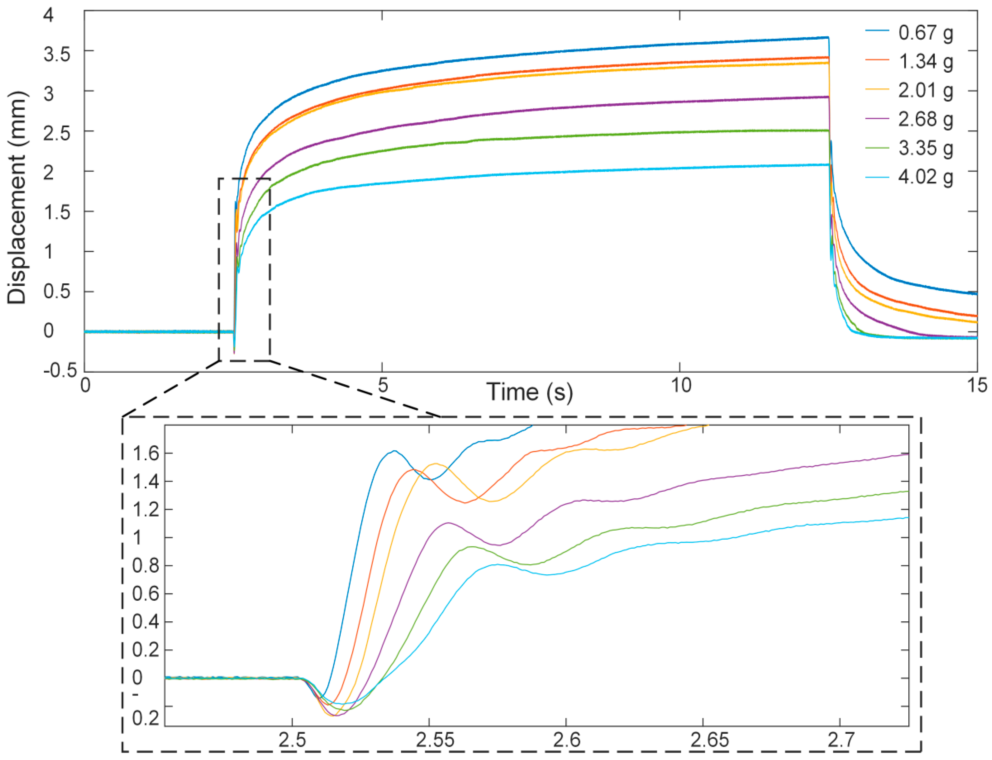
| Loads [g] | Maximum Vertical Displacements [mm] |
|---|---|
| 0.67 | 3.66 |
| 1.34 | 3.42 |
| 2.01 | 3.34 |
| 2.68 | 2.92 |
| 3.35 | 2.51 |
| 4.02 | 2.10 |
© 2019 by the authors. Licensee MDPI, Basel, Switzerland. This article is an open access article distributed under the terms and conditions of the Creative Commons Attribution (CC BY) license (http://creativecommons.org/licenses/by/4.0/).
Share and Cite
Xiang, C.; Guo, J.; Sun, R.; Hinitt, A.; Helps, T.; Taghavi, M.; Rossiter, J. Electroactive Textile Actuators for Breathability Control and Thermal Regulation Devices. Polymers 2019, 11, 1199. https://doi.org/10.3390/polym11071199
Xiang C, Guo J, Sun R, Hinitt A, Helps T, Taghavi M, Rossiter J. Electroactive Textile Actuators for Breathability Control and Thermal Regulation Devices. Polymers. 2019; 11(7):1199. https://doi.org/10.3390/polym11071199
Chicago/Turabian StyleXiang, Chaoqun, Jianglong Guo, Rujie Sun, Andrew Hinitt, Tim Helps, Majid Taghavi, and Jonathan Rossiter. 2019. "Electroactive Textile Actuators for Breathability Control and Thermal Regulation Devices" Polymers 11, no. 7: 1199. https://doi.org/10.3390/polym11071199
APA StyleXiang, C., Guo, J., Sun, R., Hinitt, A., Helps, T., Taghavi, M., & Rossiter, J. (2019). Electroactive Textile Actuators for Breathability Control and Thermal Regulation Devices. Polymers, 11(7), 1199. https://doi.org/10.3390/polym11071199