Abstract
Multiple-input multiple-output (MIMO) technology as an efficient approach to improve the transmission rate in visible light communication (VLC) has been well studied in recent years. In this paper, we focus on the MIMO VLC system using multi-color LEDs in the typical indoor scenario. Besides the correlation of the MIMO channel, the multi-color crosstalk interference and quadrangle chromaticity region are also considered to increase the practicality of this system. With the constraints of power, amplitude and chromaticity, an iterative algorithm to minimize mean-squared-error (MSE) is proposed to jointly design the precoder and equalizer. Our proposed algorithm provides an effective method to get the optimal precoder by updating optimization variables iteratively. As the equalizer matrix is fixed at each iteration, the main non-convex precoding design problem is transformed into a convex optimization problem and then solved. With the utilization of multi-color LEDs, our proposed precoding method would be promising to promote the practical applications of high-speed indoor optical wireless communication. Simulation results show that our proposed method owns better performance than conventional chromaticity-fixed schemes and zero-forcing precoding designs.
1. Introduction
In recent years, visible light communications (VLCs) have become an extremely promising new wireless communication technology [1]. Due to the large bandwidth of the visible light spectrum, VLC can provide high-speed wireless information transmission in indoor and outdoor scenarios [2]. Lighting-emitting diodes (LEDs) are commonly used as the transmitters in VLC. Generally, there are two kinds of LEDs, one is the phosphor-converted LED (pc-LED) and the other one is the multi-chip LED. Although pc-LEDs are easily accessible, their intrinsic modulation bandwidth is limited to MHz. Compared with pc-LEDs, multi-chip LEDs own a several times larger bandwidth and higher color rendering index.
To achieve abundant illumination, numerous lamps need to be placed at the same time in some scenarios. Meanwhile, these LEDs can be used as transmitters in VLC. Multi-input data streams make the high transmission rate increase significantly. Therefore, the techniques on multiple-input multiple-output (MIMO) is extensively researched in VLC. The multi-color LEDs used in these systems can improve the density of transmitters, which would undoubtedly boost transmission rate further.
MIMO VLC systems with multi-color LEDs can be used in both indoor and outdoor scenarios. In an indoor scenario, multi-color LEDs can work as the intelligent lighting solution owing to their dynamic controllable chromaticity; meanwhile, the data rate up to gigabit per second can be further improved [3,4,5]. In the outdoor scenarios, there are also various applications for high speed MIMO VLC including outdoor traffic lighting systems, signboard and display screen interaction, underwater communication, etc. [6]. For example, in the underwater network, as the turbulence severely affects the underwater VLC channels, the MIMO VLC with multi-color LEDs would be more effective to mitigate turbulence effects in the underwater environment due to its higher diversity property [7].
To make full use of MIMO VLC systems, some methods have been developed by researchers. In [8,9], the authors investigated the indoor channel characteristics of MIMO VLC systems. Besides the traditional non-imaging receiver, the imaging receiver, which is an effective candidate to separate signals from different directions, has been widely used in MIMO VLC [10]. Then, in [11,12,13], some signal design methods that exploited the spatial-collaborative property of MIMO VLC were brought forward and analyzed. Some advanced modulation formats such as orthogonal frequency division multiplexing (OFDM) are also employed in MIMO VLC systems [14]. To further improve the system performance, many transmitter design methods were put forward [15,16,17,18]. In [15], an optical power allocation method was proposed to improve the spectral efficiency with the requirements of amplitude and total optical power and bit error rate (BER). Moreover, the authors of [16] proposed a robust precoding method to solve the max-min signal-to-interference-plus-noise ratio (SINR) problem with the consideration of the inter-user interference and imperfect channel estimation. In [17], a singular value decomposition-based Chebyshev precoding was proposed to improve the performance of nonlinear MIMO VLC. Based on [17], an adaptive precoding design was further investigated for a massive MIMO VLC system in [18].
When multi-color LEDs are used in MIMO, the overlapping spectrum of multiple colors would cause inevitable crosstalk interference [19]. In [20], the authors applied an array of multi-color LEDs in MIMO VLC and proposed an optimal precoding design method to minimize total mean-squared-error (MSE) with the consideration of the color interference. However, in their works, the CCT values were fixed, and the clipping distortion of exceeding electric amplitude was neglected. In [21], an illumination-adapted transceiver was designed under chromaticity, luminance and signal range constraints with an iterative algorithm. However, they only took a single multi-color LED as the transmitter and also fixed the CCT values. As has been standardized in [22], the chromaticity difference in the region called the MacAdam ellipse on the CIE1931 chromaticity diagram could be ignored. Then, to meet the needs of LED products, chromaticity tolerances were even modified to be limited in quadrangle regions [23]. Therefore, the performance of multi-color VLC systems is able to be improved by considering the quadrangle chromaticity regions instead of fixed CCT values.
In this paper, different from the existing methods, we employ multi-color LEDs in MIMO VLC to improve the data transmission rate and consider the multi-color crosstalk and chromaticity tolerance regions to improve the system adaptivity for practical illumination scenarios. We propose a linear precoding design to minimize the MSE of the received signal under power, amplitude and chromaticity constraints. With the precoding design transformed into a convex optimization problem, an iterative algorithm is designed to derive the optimal precoder.
The main contributions of this paper are summarized as follows:
- We construct the MIMO VLC system model based on multi-color LEDs and formulate the precoding design problem to minimize the total MSE under multiple lighting constraints.
- Unlike the conventional multi-color precoding method designed for fixed CCT values, our proposed method is optimized under the chromaticity constraint in a quadrangle range.
- Considering the multi-color interference, our proposed MSE minimization algorithm provides an effective method to get the optimal precoder by updating optimization variables iteratively.
- The transmission data rate of traditional white light MIMO VLC systems is improved by the utilization of multi-color LEDs, and our proposed method would be applicable in high speed broadband optical wireless communication.
The remainder of this paper is laid out as follows: Section 2 mainly introduces the MIMO VLC system model. Section 3 indicates the main optimization problem and lighting constraints. In Section 4, we propose an iterative algorithm to solve the optimization and analyze the complexity. Simulation results are demonstrated in Section 5, and conclusions are drawn out in Section 6.
2. System Model
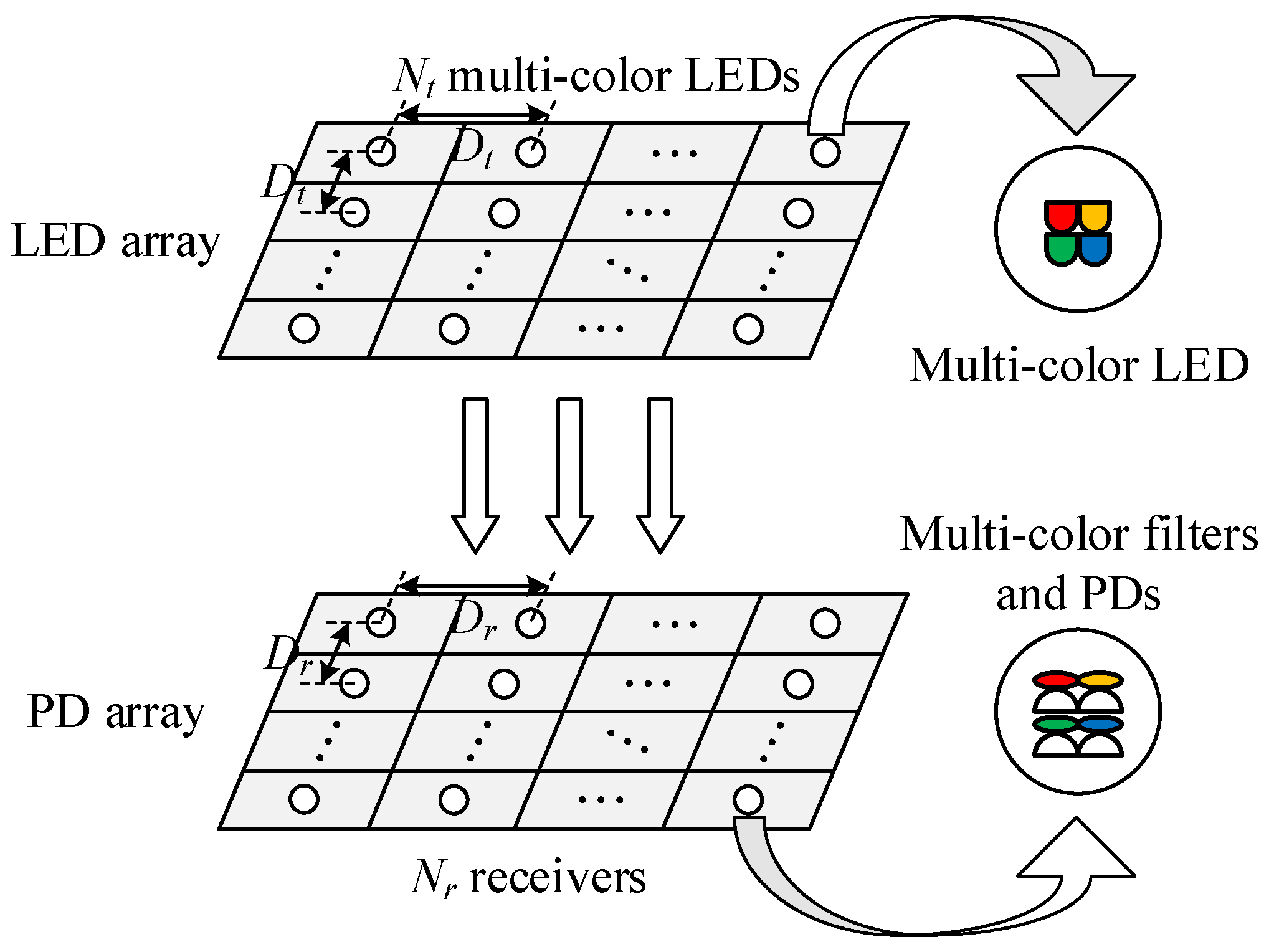
We consider N-color LED transmitters and receivers (each receiver consists of N-color filters and N PDs) to form an MIMO VLC system. The system model is shown in Figure 1.

Figure 1.
The system model of MIMO VLC using multi-color LEDs.
At the transmitter side, the source data are an multi-level pulse amplitude modulation (PAM) vector with zero mean, , where the k-th color signal vector is . The M-level PAM signal is formed in the range of , , where K is the number of bits per transmitted symbol. We modulate the source data with precoder and then add an positive offset vector to each stream to guarantee the non-negativeness of the intensity of transmitted signals. Therefore, the transmitted signals can be written as:
We first consider the channel matrix in a single color band c. For the k-th color, the channel gain between the j-th LED and i-th PD in the discrete-time channel matrix is determined by [24]:
where m is the order of Lambertian emission given by , in which is the half power angle of the LED, is the detector area of the receiver, is the receiver responsibility, is the distance between the j-th LED chip and the i-th PD, is the angle of irradiance and is the angle of incidence. As has been studied in [3], the diffuse light component in an indoor scenario is much lower than the weakest line-of-sight (LOS) component received, so here, we only take the LOS components of visible light into account.
Due to the overlapping spectrum of multiple colors and imperfect optical filters in receivers, the multi-color crosstalk in the overall channel matrix needs to be considered. As the overlap of the color spectrum usually occurs between two adjacent colors, for simplicity, only the crosstalk between adjacent colors is measured in the channel matrix [20]. The overall channel matrix in the MIMO VLC system using multi-color LEDs is given by:
where is the electrical-optical-electrical (EOE) channel matrix, is defined as the crosstalk interference ratio and .
At the receiver side, the received signal vector is sorted by N colors written as , where the k-th color received signal vector is . Therefore, the received signal can be expressed as:
where is the additive white Gaussian noise (AWGN) vector with zero mean and noise variance of , . Before the equalization of detector, the offset vector , which carries no information, can be subtracted from . Then, the received signal after subtraction can be written as:
In this paper, we adopt the linear minimum mean-squared-error (MMSE) equalizer to detect the received signal. Transmitted symbols estimated by the MMSE equalizer can be represented as follows:
3. Problem Formulation
With the MMSE equalizer employed in this MIMO VLC system, the mean-squared-error correlation matrix could be expressed as:
After plugging into Equation (7), we can derive:
where denotes the auto-correlation matrices of the source data, , and denotes the auto-correlation matrices of noise, . Based on Equation (8), the MSE can be derived as:
In an indoor scenario, MIMO VLC systems ought to guarantee stable wireless communication while satisfying practical white light illumination demands. Therefore, our work would be done under multiple lighting constraints as follows.
(1) Total power constraint
In a MIMO VLC system using multi-color LEDs, to offer a constant white light illumination, the total power of multiple color chips in each multi-color LED needs to be equal and invariable. Here, we define selection matrices , where ⊗ denotes the Kronecker product and represents the j-th column of the identity matrix , . Therefore, the total power constraint can be written as:
where denotes the one-norm and is the total optical power of each white light LED. is the optical power vector of multiple color streams, , where the optical power vector of the k-th color is . The transformation relationship between and the DC bias vector can be written as:
where the notation ∘ denotes the Hadamard product (i.e., ). is the luminance flux-forward current conversion coefficient vector.
(2) Amplitude constraint
To guarantee the nonnegativity of transmitted intensity signal , we need the minimum value of to be larger than . As the modulated PAM signal vector is limited in the range of , we have:
Therefore, the nonnegative constraint can be satisfied by letting:
where .
The transmitted signal would suffer clipping distortion when the amplitude exceeds the maximum electric amplitude, so each electric stream of multi-color LEDs has a maximum forward current limitation. We have the constant coefficient vector to convert the luminous flux to the forward current. Assuming that all the chips with the same color of different LEDs keep the same photoelectric property, there is:
where is the maximum forward current vector, .
(3) Chromaticity constraint
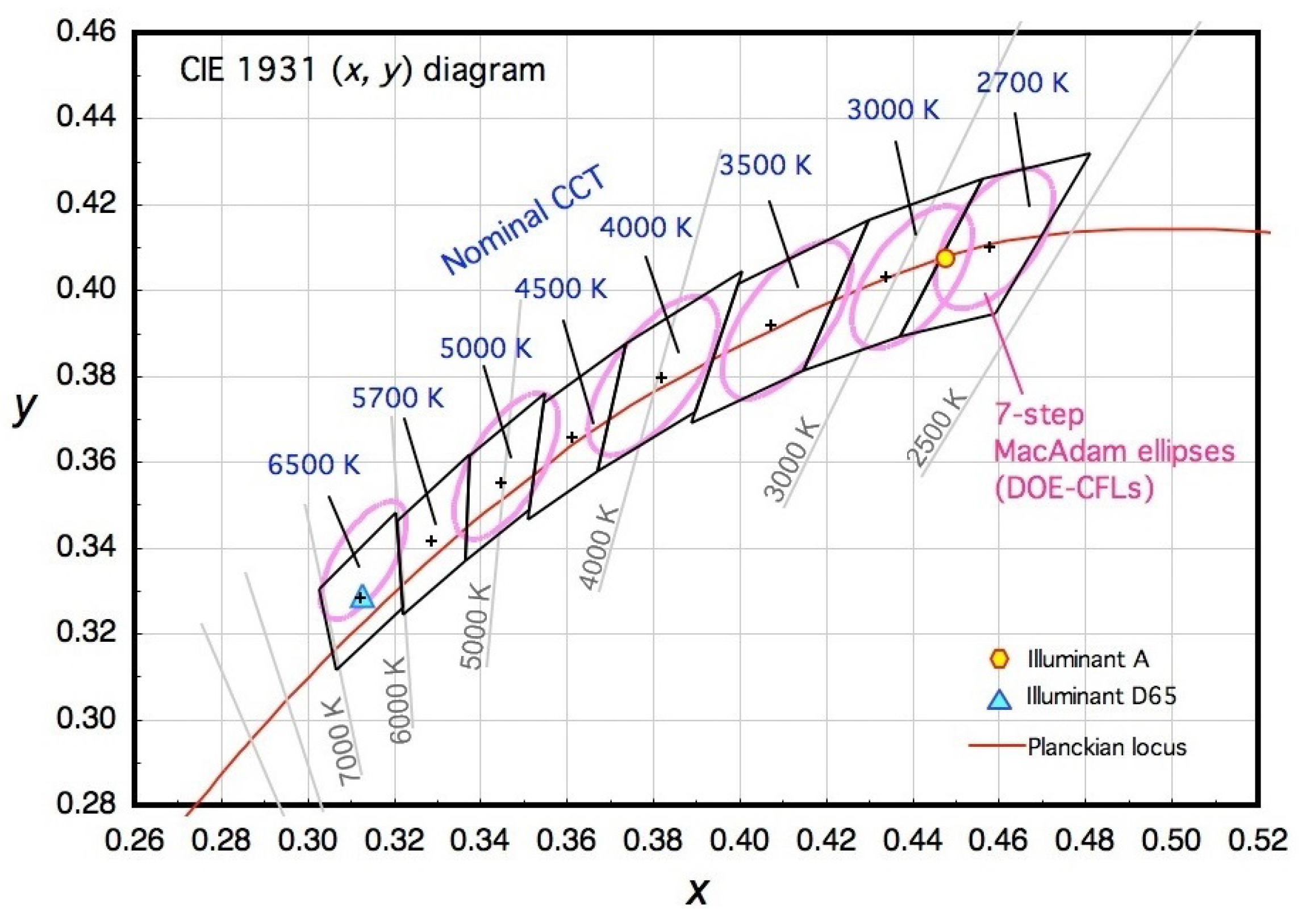
Chromaticity is the basic characteristic of the color perceived by human eyes. In the ANSI C78.376–2001 [22], seven-step MacAdam ellipses are used to define chromaticity tolerances of perceptible color differences for fluorescent lamps. As the chromaticity specifications in that standard have been modified to meet the needs of LED products [23], chromaticity coordinates are located in quadrangles rather than ellipses being specified to describe chromaticity tolerances approximately. These color tolerance regions are graphically shown in the CIE 1931 chromaticity diagram as Figure 2 [25].
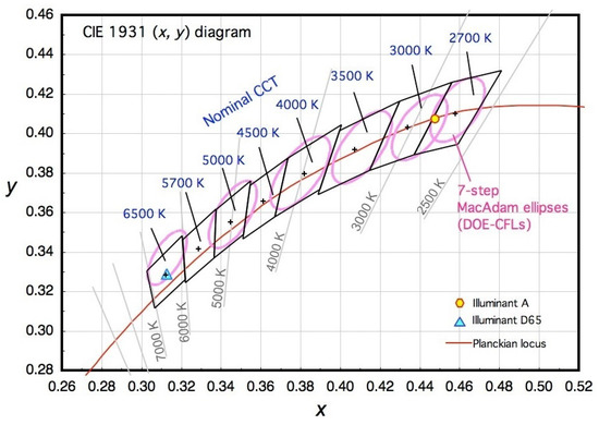
Figure 2.
Graphical representation of the chromaticity tolerance regions of LED products on the CIE 1931 chromaticity diagram.
Based on Grassmann’s laws of color mixture [26], the chromaticity coordinate of mixed color light can be calculated by multiple monochromatic coordinates as:
where and are coefficient vectors and denotes the average optical power percentage vector of N colors.
Thus, the average optical power percentage of the j-th LED can be expressed as:
Based on Equation (11), there is a transformation relationship between and the DC bias vector as follows:
Therefore, the constraints of the mixed white light chromaticity in a specific quadrangle can be given by:
where is a coefficient constant determined by the quadrangle vertices in chromaticity diagrams, which is given in [23], , .
To simplify the expression of Constraint (20), we denote:
Then, we define , and is an matrix. Finally, the chromaticity constraint can be expressed as:
where is an zero vector.
Considering the above three lighting constraints in this MIMO VLC system using multi-color LEDs, the main problem of our paper is formulated as follows:
The objective function of Problem (23) is related to three elements , , , and the offset vector is also indirectly constrained by . It is hard to solve Problem (23) without any transformation because this problem is a non-convex function with multiple variables and constraints. In the next section, we propose an iterative method to transform the optimization problem into a convex problem and then work it out.
4. Linear Precoding Design
In this section, we propose a linear precoding design based on an iterative optimization method. After transforming the non-convex optimization problem into a convex problem, the optimal precoder can be derived under multiple lighting constraints.
It could be observed that the optimal is only dependent on since both and are given. Here, we use the transformations and ; the first item of Equation (9) can be rewritten as [28]:
For a fixed , the optimal can be seen as a known matrix. After the value of matrix is given, Equation (25) is obviously a quadratic item related to . Meanwhile, the items and in Equation (9) are linear with , while and are constant. Thus, the objective function is convex with respect to .
Finally, the main optimization Problem (23) with fixed is rewritten as:
It can be observed that the first and third constraints are a series of linear inequations, while the second equation constraints are also linear. Therefore, the optimization Problem (26) is convex at each iteration. This convex problem can be solved by optimization algorithms such as the interior point algorithm. In this paper, we adopt a toolbox for MATLAB called CVX to solve this convex optimization problem [29].
Our proposed iterative precoding design method is concluded in Algorithm 1.
| Algorithm 1: Iterative linear precoding design method |
In Algorithm Table 1, we first create the initial and randomly satisfying all the constraints. Then, at the n-th iteration, the optimal can be calculated by Equation (24) using . Based on the fixed , the optimal solution of and would be derived by the optimization Problem (26). Subsequently, the optimal could be obtained at the next iteration. After an amount of iterations, the iterative solution of and would be gained. Since the values of initial and are randomly chosen, we would repeat the whole iteration procedure for times to achieve an accurate solution of .

Table 1.
Simulation parameters used in the MIMO VLC system.
Now, we analyze the complexity of our proposed method in Algorithm 1. After initial and are randomly chosen, the main iteration procedure would be executed. At each iteration, the optimal is calculated using Equation (24), which costs the complexity of due to the calculation of matrix inversion and the matrix product. After the optimal value of is achieved, the convex optimization would be solved by the CVX toolbox, which costs the complexity of , where T denotes the inner iteration number of the interior point method. Therefore, the total complexity of each iteration is . Compared with the conventional zero-forcing (ZF) precoder whose complexity is [30], our proposed method pays more complexity to gain a better performance.
5. Simulation Results
In this section, we carry out some simulations in the practical indoor MIMO VLC scenario. Simulation parameters of the MIMO VLC system are shown in Table 1. Note that the angle of irradiance and the angle of incidence are calculated according to the position arrangements of devices. The two-level PAM signal formed in the range of is transmitted. RAGBLEDs chosen from the LUXEON C Color product line (LUMILEDS) are employed as the transmitters [31]. In the iterative algorithm, we set the iteration time and the loop time to obtain a trade-off between the complexity and precision.
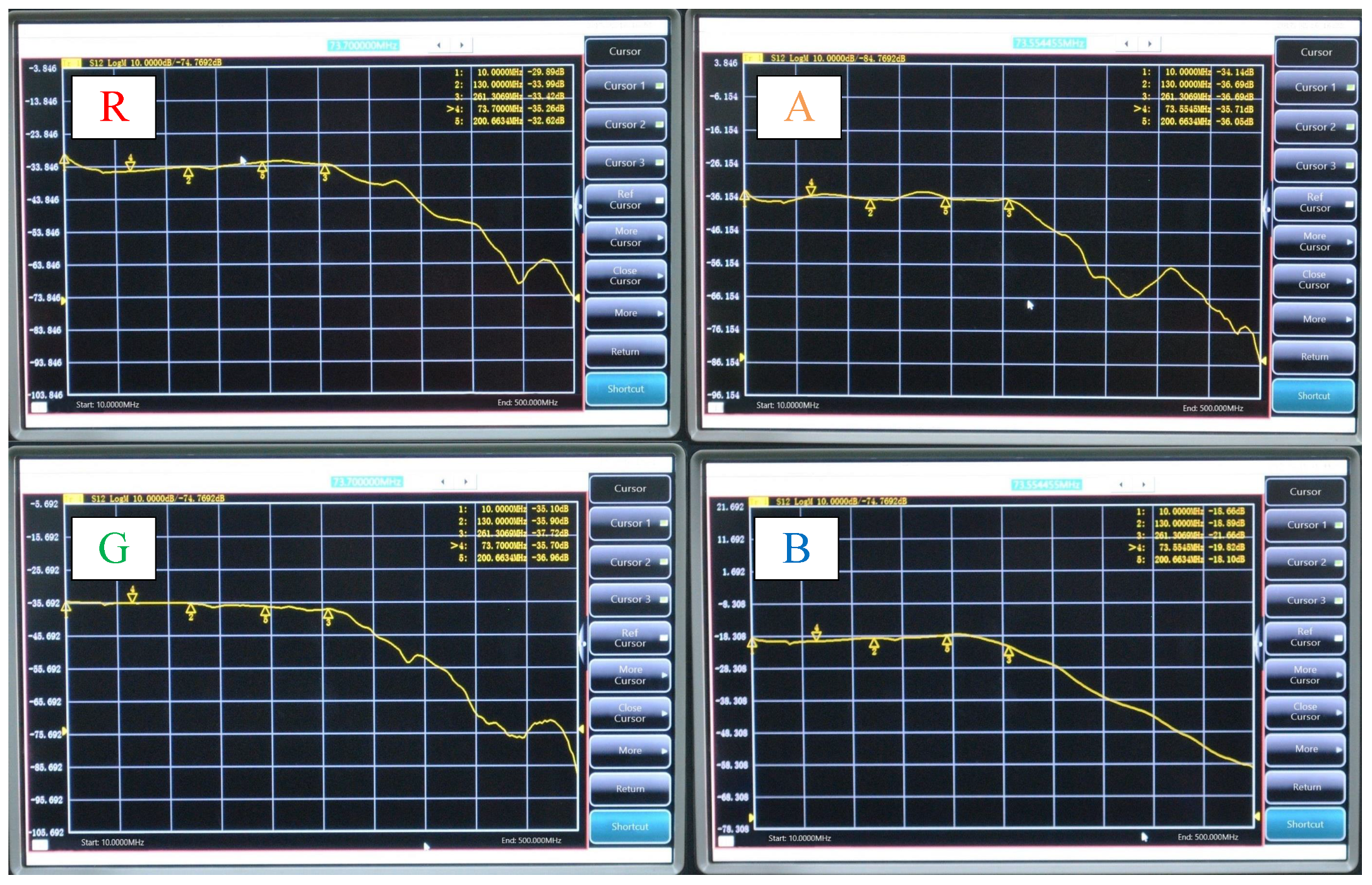
To extend the limited modulation bandwidth of commercial multi-color LEDs, the pre-equalization technology is utilized in our MIMO VLC system [32]. As shown in Figure 3, based on a single and cascaded bridged-T amplitude equalizer, the bandwidth of multiple color chips is extended to about 260 MHz from 100 MHz after the equalization. After introducing the roll-off factor , the total data rate R can be calculated as:
B is the bandwidth of the multi-color LED.
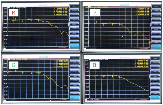
Figure 3.
The amplitude-frequency response characteristics of multiple colors after pre-equalization.
Thus, the throughput of our proposed system can be derived by:
where is the data transmission error property.
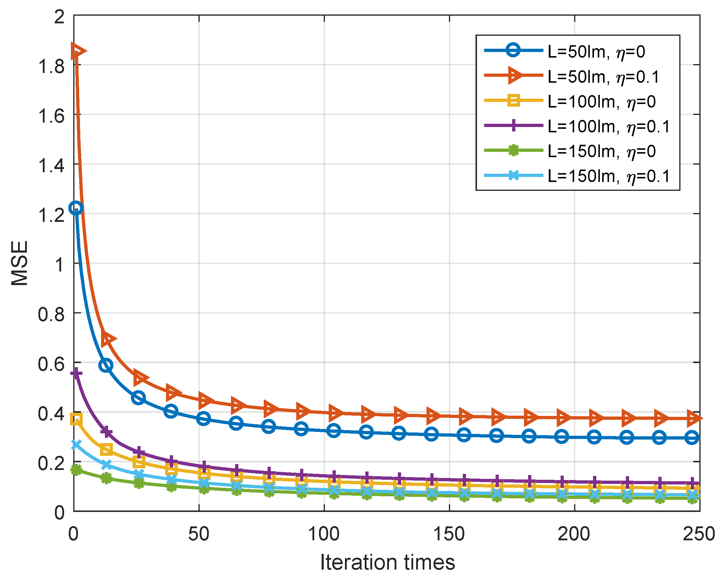
We first present the convergence performance of our proposed iterative algorithm. Figure 4 demonstrates the convergence performance versus luminous flux with different interference ratio when CCT = 5000 K. It can be seen that the values of MSE converge to the optimal solutions after about 100 iterations, so the iteration time we set is reasonable. Besides, the convergence value of MSE when is always smaller than obviously due to the lower crosstalk interference.
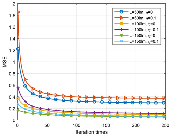
Figure 4.
Convergence performance of the iterative algorithm with different luminous fluxes and interference ratios when CCT = 5000 K.
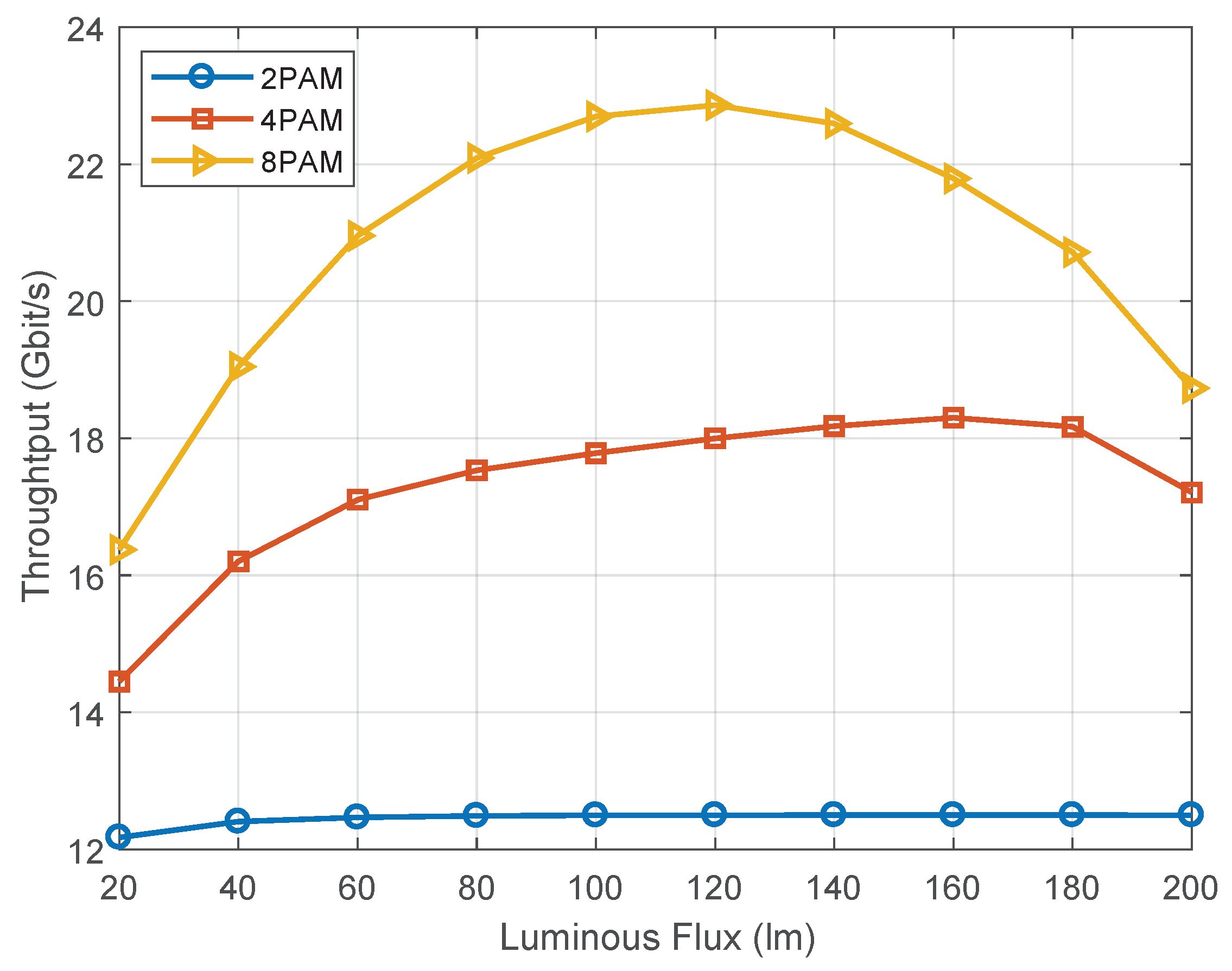
The throughput performance of our system for different order of PAM modulation when CCT = 5000 K is brought forward in Figure 5. The data transmission error property is approximated by the bit error rate (BER). It could be seen that the throughput of this system achieves over 10 Gbit/s, which is higher than traditional white light MIMO VLC systems [32]. Besides, we could also draw out the conclusion that the higher-order modulation would suffer more severe performance loss caused by the clipping distortion.
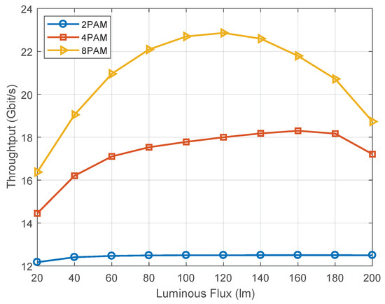
Figure 5.
The throughput performance of the proposed precoder for different modulation orders. PAM, pulse amplitude modulation.
Next, we compare the BER performance of our proposed method with some conventional precoding methods. The BER is calculated by the Monte Carlo method, and the length of transmitted data is set to be in the simulations. In [21], a precoding design is proposed for fixed chromaticity (denoted as the chromaticity-fixed method). Figure 6 shows the BER performance of our proposed precoder and the chromaticity-fixed precoder versus luminous flux with different interference ratios when CCT = 5000 K. Compared with the chromaticity-fixed precoder, our proposed precoder always shows better BER performances since we consider the quadrangle chromaticity region. Moreover, it could be seen that the performance gap decreases with the increasing of crosstalk ratio. As the luminous flux increases, the BER curves show a down and up tendency because the clipping distortion happens when the luminous flux gets too high.
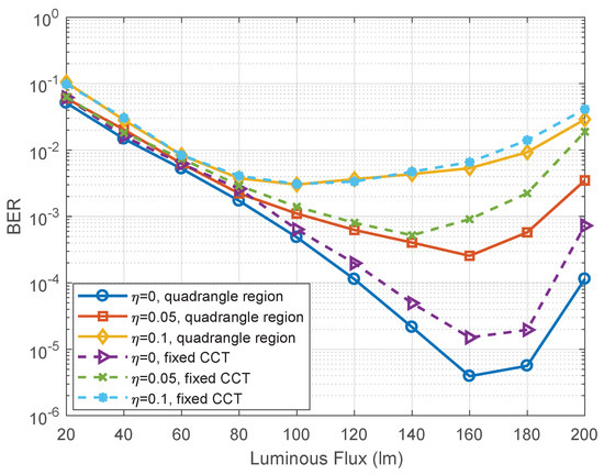
Figure 6.
The BER performance of the proposed precoder and chromaticity-fixed precoder versus luminous flux with different interference ratios when CCT = 5000 K.
Then, we compare our proposed precoder with the conventional ZF precoder. The ZF precoder can be written as:
where denotes a diagonal matrix. The value of is optimized to satisfy the lighting constraints for indoor scenarios. The BER performances of these two precoders versus luminous flux with different CCT values is demonstrated in Figure 7. It can be seen that the performance of our proposed precoder outperforms the traditional ZF precoder, and the BER curves also show a down and up tendency.
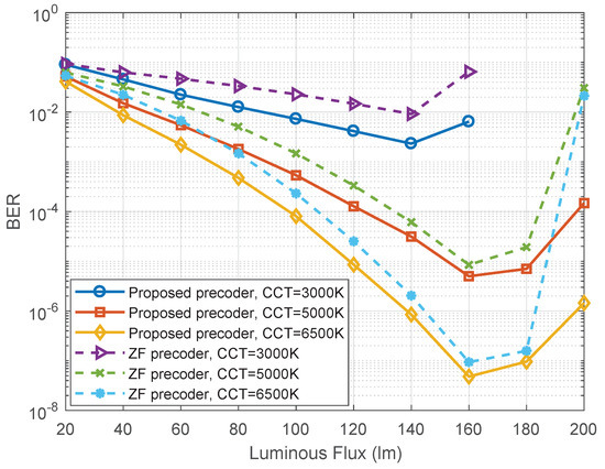
Figure 7.
The BER performance of the proposed precoder and ZF precoder versus luminous flux with different CCT values when .
Furthermore, the BER performances of our proposed precoder for six different CCT values (i.e., 3000 K, 3500 K, 4000 K, 4500 K, 5000 K, 6500 K) when are shown in Figure 8. The curves for different CCT values also own the same tendency as the above figures. With a larger CCT value, the BER performance is better. This is because the percentage of blue light is the smallest portion of white light, and it gets higher as the CCT value increases; then, the power allocation of each color becomes more balanced, and better BER performance can be achieved.
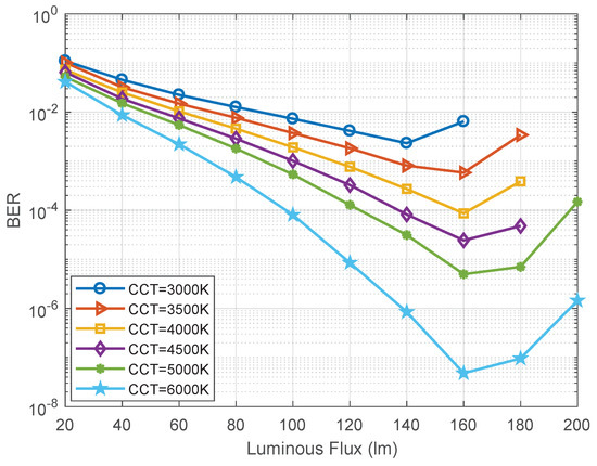
Figure 8.
The BER performance of the proposed precoder for different CCT values when .
6. Conclusions
In this paper, we have studied a joint optimization problem of the precoder and equalizer design in the proposed MIMO VLC system using multi-color LEDs. To increase the practicality of this system, we have further taken the crosstalk interference of multiple colors and the quadrangle chromaticity constraint into account. With considering the total power, amplitude and chromaticity constraints, an iterative MSE minimization algorithm has been proposed to transform the main non-convex optimization problem into a convex optimization problem. Simulation results show that our proposed method owns better performance than conventional fixed CCT schemes and ZF design methods.
Author Contributions
Conceptualization, Y.X. and Y.-J.Z.; methodology, Y.X. and Y.-J.Z.; software, Y.X.; validation, Y.X., Y.-J.Z. and Z.-G.S.; formal analysis, Y.X. and Z.-G.S.; investigation, Y.X.; resources, Y.X.; data curation, Y.X.; writing-original draft preparation, Y.X.; writing-review and editing, Y.-J.Z. and Z.-G.S.; visualization, Y.X.; supervision, Y.-J.Z.; project administration, Y.-J.Z.; funding acquisition, Y.-J.Z.
Funding
This research was sponsored in part by Grant No. 61671477 from China NSFC and in part by Grant No. 160 2015B010112001 from the Major Scientific and Technological Project of Guangdong Province, China.
Conflicts of Interest
The authors declare no conflict of interest.
Abbreviations
The following abbreviations are used in this manuscript:
| MIMO | Multiple-input multiple-output |
| VLC | Visible light communication |
| LED | Lighting-emitting diodes |
| WDM | Wavelength division modulation |
| SINR | Signal-to-interference-plus-noise ratio |
| CRI | Color rendering index |
| CCT | Correlated color temperature |
| MSE | Mean-squared-error |
| MMSE | Minimum mean-squared-error |
| ZF | Zero-forcing |
References
- Elgala, H.; Mesleh, R.; Haas, H. Indoor optical wireless communication: Potential and state-of-the-art. IEEE Commun. Mag. 2011, 49, 56–62. [Google Scholar] [CrossRef]
- Pathak, P.H.; Feng, X.; Hu, P.; Mohapatra, P. Visible light communication, networking, and sensing: A survey, potential and challenges. IEEE Commun. Surv. Tutor. 2015, 17, 2047–2077. [Google Scholar] [CrossRef]
- Zeng, L.; O’Brien, D.; Minh, H.; Faulkner, G.; Lee, K.; Jung, D.; Oh, Y.; Won, E.T. High data rate multiple input multiple output (MIMO) optical wireless communications using white LED lighting. IEEE J. Sel. Areas Commun. 2009, 27, 1654–1662. [Google Scholar] [CrossRef]
- Azhar, A.H.; Tran, T.A.; O’Brien, D. A Gigabit/s indoor wireless transmission using MIMO-OFDM visiblelight communications. IEEE Photonics Technol. Lett. 2013, 25, 171–174. [Google Scholar] [CrossRef]
- Rajbhandari, S.; Jalajakumari, A.V.; Chun, H.; Faulkner, G.; Cameron, K.; Henderson, R.; Tsonev, D.; Haas, H.; Xie, E.; McKendry, J.J.; et al. A multigigabit per second integrated multiple input multiple output VLC demonstrator. J. Lightw. Technol. 2017, 35, 4358–4365. [Google Scholar] [CrossRef]
- Karunatilaka, D.; Zafar, F.; Kalavally, V.; Parthiban, R. LED based indoor visible light communications: State of the art. IEEE Commun. Surv. Tutor. 2015, 17, 1649–1678. [Google Scholar] [CrossRef]
- Jamali, M.V.; Nabavi, P.; Salehi, J.A. MIMO underwater visible light communications: Comprehensive channel study, performance analysis, and multiple-symbol detection. IEEE Trans. Veh. Technol. 2018, 67, 8223–8237. [Google Scholar] [CrossRef]
- Fath, T.; Haas, H. Performance comparison of MIMO techniques for optical wireless communications in indoor environments. IEEE Trans. Commun. 2013, 61, 733–742. [Google Scholar] [CrossRef]
- Chvojka, P.; Zvanovec, S.; Haigh, P.A.; Ghassemlooy, Z. Channel characteristics of visible light communications within dynamic indoor environment. J. Lightw. Technol. 2015, 33, 1719–1725. [Google Scholar] [CrossRef]
- Chen, T.; Liu, L.; Tu, B.; Zheng, Z.; Hu, W. High-spatial-diversity imaging receiver using fisheye lens for indoor MIMO VLCs. IEEE Photonics Technol. Lett. 2014, 26, 2260–2263. [Google Scholar] [CrossRef]
- Zhu, Y.J.; Wang, W.Y.; Zhang, J.K.; Zhang, Y.Y. Constellation collaborated nonlinear orthogonal space-time block codes with fast maximum-likelihood detection. IEEE Trans. Veh. Technol. 2017, 66, 513–528. [Google Scholar] [CrossRef]
- Xu, K.; Yu, H.Y.; Zhu, Y.J.; Cai, H.B. Channel-adaptive spacecollaborative constellation design for MIMO VLC with fast maximum likelihood detection. IEEE Access 2017, 5, 842–852. [Google Scholar] [CrossRef]
- Zhu, Y.J.; Liang, W.F.; Wang, C.; Wang, W.Y. Energy-efficient constellations design and fast decoding for space-collaborative MIMO visible light communications. Opt. Commun. 2017, 383, 260–273. [Google Scholar] [CrossRef]
- Chen, C.; Wu, D.; Zhong, W.D. Non-Hermitian symmetry orthogonal frequency division multiplexing for multiple-input multiple-output visible light communications. IEEE/OSA J. Opt. Commun. Netw. 2017, 9, 36–44. [Google Scholar] [CrossRef]
- Park, K.H.; Ko, Y.C.; Alouini, M.S. On the power and offset allocation for rate adaptation of spatial multiplexing in optical wireless MIMO channels. IEEE Trans. Commun. 2013, 61, 1535–1543. [Google Scholar] [CrossRef]
- Sifaou, H.; Kammoun, A.; Park, K.H.; Alouini, M.S. Robust transceivers design for multi-stream multi-user MIMO visible light communication. IEEE Access 2017, 5, 2169–3536. [Google Scholar] [CrossRef]
- Mitra, R.; Bhatia, V. Precoded Chebyshev-NLMS-based pre-distorter for nonlinear LED compensation in NOMA-VLC. IEEE Trans. Commun. 2017, 65, 4845–4856. [Google Scholar] [CrossRef]
- Jain, S.; Mitra, R.; Bhatia, V. Adaptive precoding based detection algorithm for massive MIMO visible light communication. IEEE Commun. Lett. 2018, 99, 1842–1845. [Google Scholar] [CrossRef]
- Gong, C.; Li, S.; Gao, Q.; Xu, Z. Power and rate optimization for visible light communication system with lighting constraints. IEEE Trans. Signal Process. 2015, 63, 4245–4256. [Google Scholar] [CrossRef]
- Wang, R.; Gao, Q.; You, J.; Liu, E.; Wang, P.; Xu, Z.; Hua, Y. Linear transceiver designs for indoor MIMO visible light communications under lighting constraints. IEEE Trans. Commun. 2017, 99, 2494–2508. [Google Scholar] [CrossRef]
- Dong, J.M.; Zhu, Y.J.; Zhang, Y.Y.; Sun, Z.G. Illumination-adapted transceiver design for quadrichromatic light-emitting diode based visible light communication. IEEE Photonics J. 2018, 10. [Google Scholar] [CrossRef]
- ANSI NEMA ANSLG C78.376–2001: Specications for the Chromaticity of Fluorescent Lamps; ANSI, American National Standard Institute: Washington, DC, USA, 2001.
- ANSI NEMA ANSLG C78.377–2008: Specications for the Chromaticity of Solid State Lighting Products; ANSI, American National Standard Institute: Washington, DC, USA, 2008.
- Komine, T.; Nakagawa, M. Fundamental analysis for visible-light communication system using LED lights. IEEE Trans. Consum. Electron. 2004, 50, 100–107. [Google Scholar] [CrossRef]
- Smith, T.; Guild, J. The CIE colorimetric standards and their use. Trans. Opt. Soc. 2002, 33, 73. [Google Scholar] [CrossRef]
- Wyszecki, G.; Stiles, W.S. Color Science: Concepts and Methods, Quantitative Data and Formulas. Phys. Today 1968, 21, 83–84. [Google Scholar] [CrossRef]
- Palomar, D.P.; Cioffi, J.M.; Lagunas, M.A. Joint Tx-Rx beamforming design for multicarrier MIMO channels: A unified framework for convex optimization. IEEE Trans. Signal Process. 2003, 51, 2381–2401. [Google Scholar] [CrossRef]
- Ying, K.; Qian, H.; Baxley, R.J.; Yao, S. Joint optimization of precoder and equalizer in MIMO VLC systems. IEEE J. Sel. Areas Commun. 2015, 33, 1949–1958. [Google Scholar] [CrossRef]
- Grant, M.; Boyd, S. CVX: Matlab Software for Disciplined Convex Programming, version 1.21. Glob. Optim. 2008, 33, 155–210. [Google Scholar]
- Yu, Z.; Baxley, R.J.; Zhou, G.T. Multi-user MISO broadcasting for indoor visible light communication. In Proceedings of the 2013 IEEE International Conference on Acoustics, Speech and Signal Processing, Vancouver, BC, Canada, 26–31 May 2013; pp. 4849–4853. [Google Scholar] [CrossRef]
- Lumileds. LUXEON C Color Line Product Datasheet. 2018. Available online: http://www.lumileds.com/uploads/571/DS144-pdf (accessed on 2 February 2018).
- Huang, X.X.; Shi, J.Y.; Li, J.H.; Wang, Y.G.; Chi, N. A Gb/s VLC Transmission Using Hardware Preequalization Circuit. IEEE Photonics Technol. Lett. 2015, 27, 1915–1918. [Google Scholar] [CrossRef]
© 2018 by the authors. Licensee MDPI, Basel, Switzerland. This article is an open access article distributed under the terms and conditions of the Creative Commons Attribution (CC BY) license (http://creativecommons.org/licenses/by/4.0/).