Abstract
Swing arc narrow gap GMA welding experiments were carried out with a Box–Behnken response surface design. Weld metal and heat-affected sizes were measured from the joints obtained, and an ANOVA was performed to obtain well-fitting models for definition of the heat-affected length. Overlapping patterns and microstructures were analyzed and observed in zones within the heat-affected length through the thickness direction. In addition, thermal processes in typical zones of HAZs were calculated by FEM and analyzed to explain the patterns in the typical coarse grain heat-affected zones (CG-HAZs) with thermal simulated microstructures attached. It was realized that a single pass could only be confused with an austenitized process by two passes. The coarse grain heat-affected zone of a single pass could be divided into an unaltered coarse grain heat-affected zone (UACG-HAZ), a supercritically reheated coarse grain heat-affected zone (SCRCG-HAZ) and an intercritically reheated heat-affected zone (IRCG-HAZ). It is likely that there would be an intercritically reheated UACG-HAZ upon the UACG-HAZ. The microstructures in the CG-HAZs and the UACG-HAZ were mainly lath bainite and a little acicular ferrite; the microstructures in the SCRCG-HAZ were short lath bainite, granular bainite and acicular ferrite and the microstructures in the IRCG-HAZ were massive textures and secondary austenite decomposition products. The cooling times in the typical bainite transformation procedures were similar to one another in a secondary austenitized process and significantly longer than those in a single austenitized thermal cycle, which caused similar patterns in reheated CG-HAZs and an increase in acicular ferrite compared to CG-HAZs. The prior austenite grain sizes caused differences among the reheated CG-HAZs.
1. Introduction
Steel plates used in offshore and marine structures have become thicker to meet the needs of extreme service conditions. Thus, a larger number of welding operations for thick-walled steel structures would be required, which brings challenges to the shipbuilding and offshore industries [1,2,3]. High heat input methods such as submerged arc welding (SAW) and electro-gas welding (EGW) have been widely used in the welding of ship plate steels with various kinds of strength grades because of the higher manufacturing efficiency. Admittedly, when using conventional HSLA steels, there are problems of worse microstructures and severe decreases in the heat-affected zones obtained by high heat input methods [4,5,6,7]. With regards to the conflict between efficiency and mechanical properties, optimized and modified thick-walled steels for high heat input welding were developed.
The steel for high heat input welding is low-carbon microalloyed. Oxide metallurgical elements or nitride metallurgical elements were added to obtain inclusion particles with a proper size and distribution during the TMCP [8]. Therefore, the size of the primary austenite grains would not severely increase due to the particles preventing the grain growth. Furthermore, the particles could also act as nucleating particles of acicular ferrite (AF) [9,10,11,12,13,14]. Nowadays, steels for high heat input welding from AH32 grade to FH550 grade have been well developed. Conventional HSLA steels used in offshore and marine structures will also be gradually replaced by these microalloy steels.
The development of microalloy steels relieves the metallurgical problems brought by long-standing high temperatures. However, thick-walled plates require large angle grooves, which would cause significant stress accumulation at the root of the groove under multiple high heat input thermal cycles. Narrow gap welding techniques could relieve the problems of residual stress and deformation caused by groove types. Narrow gap GMA welding is a high-efficiency welding technology. A deep, narrow and almost vertical gap is used in narrow gap welding, which would significantly reduce the filling metal and the processing time. In addition, a lower filling size in the width direction and a lower heat input per pass cause less residual stress and deformation [15,16,17,18]. It is believed that narrow gap GMA welding could be applied well to the manufacturing of marine engineering. However, because of the small filling size and multilayer filling procedure, the thermal processes and microstructures of heat-affected zones become complex. It is necessary to find out the thermal cycles during narrow gap GMA welding and declare the transformation of the heat-affected zones to further estimate the application of narrow gap GMA welding to thick-walled marine steel plates.
In this study, EH40 grade ship plate microalloyed steels were used. The filling size of the solidification area and the size of the heat-affected zones under various processing parameters were obtained by swing arc narrow gap GMA welding. The thermal processes and distribution of the coarse grain heat-affected zones (CG-HAZs) were analyzed. The microstructures of typical CG-HAZs were also investigated.
2. Experimental Materials, Methods and Models
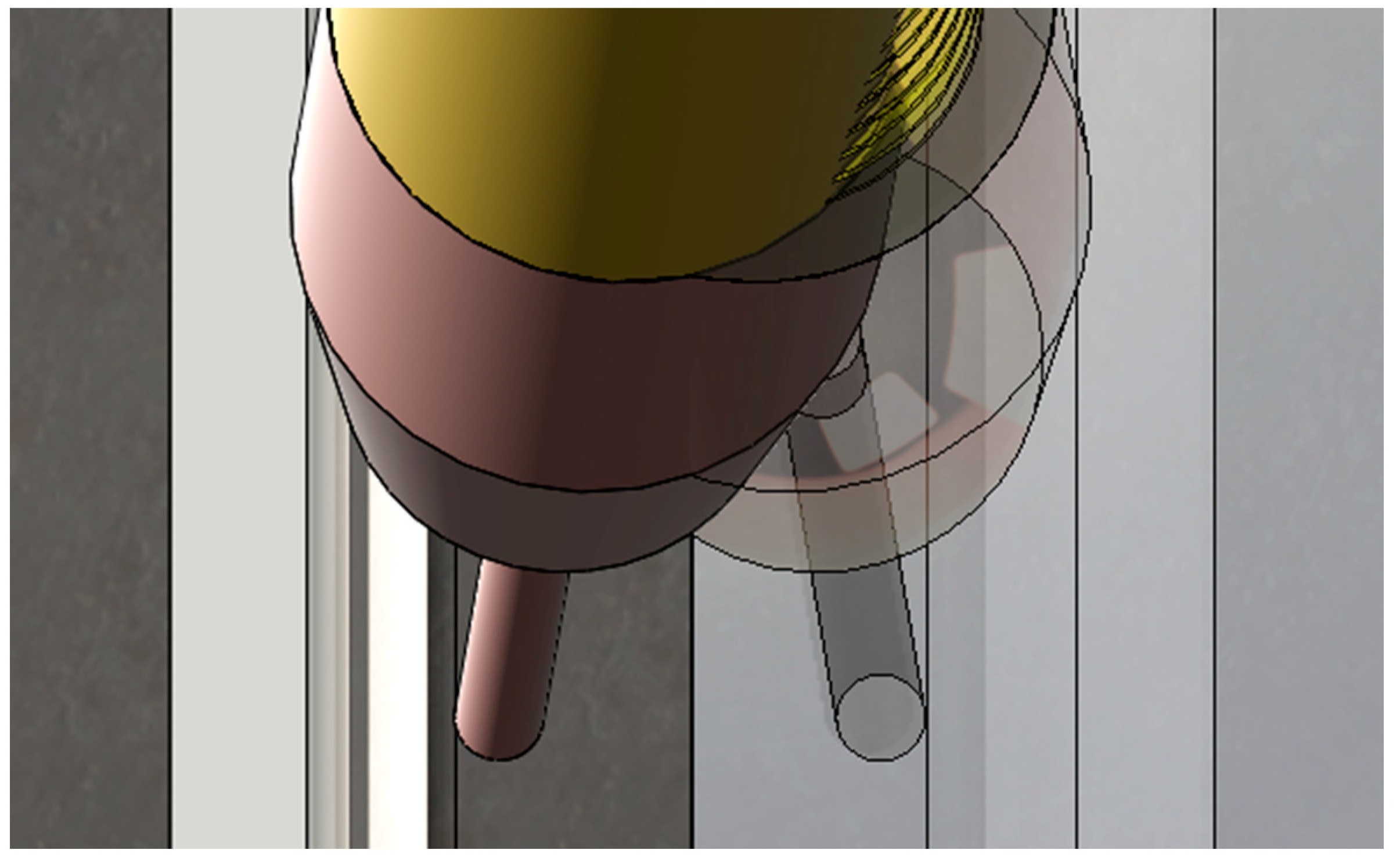
A swing arc narrow gap GMA welding process was carried out using a CLOOS 503 power source (from Germany) and a self-designed welding torch, during which the arc and the tip of the wire oscillated as the contact tube oscillated, driven by a servo motor. The contact tube was bent near the end with an angle of 15° between the contact tip axis and the contact tube axis to attain oscillation of the welding arc, as given in Figure 1.

Figure 1.
Contact tip and the wire of the self-designed torch.
No monitoring system was used during the welding procedure in this study. All processing parameters given in this study were the set values of the machines. The power source was operated in a U-I pulsed mode with a frequency of 220 Hz. The peak voltage and base current were input and controlled in this mode. EH40 grade microalloyed steels were used as the base metal, and MG-51T welding wire with a diameter of 1.2 mm was used as the filler metal. Furthermore, 90% Ar–10% CO2 was used as the shielding gas with a flow rate of 25 L/min. The nominal compositions of the base metal and the filler metal are given in Table 1. The processing parameters and ranges used in this study are shown in Table 2.

Table 1.
Nominal compositions of EH40 plates and MG-51T wire (wt%).
Table 2.
Processing parameters set in the machines.
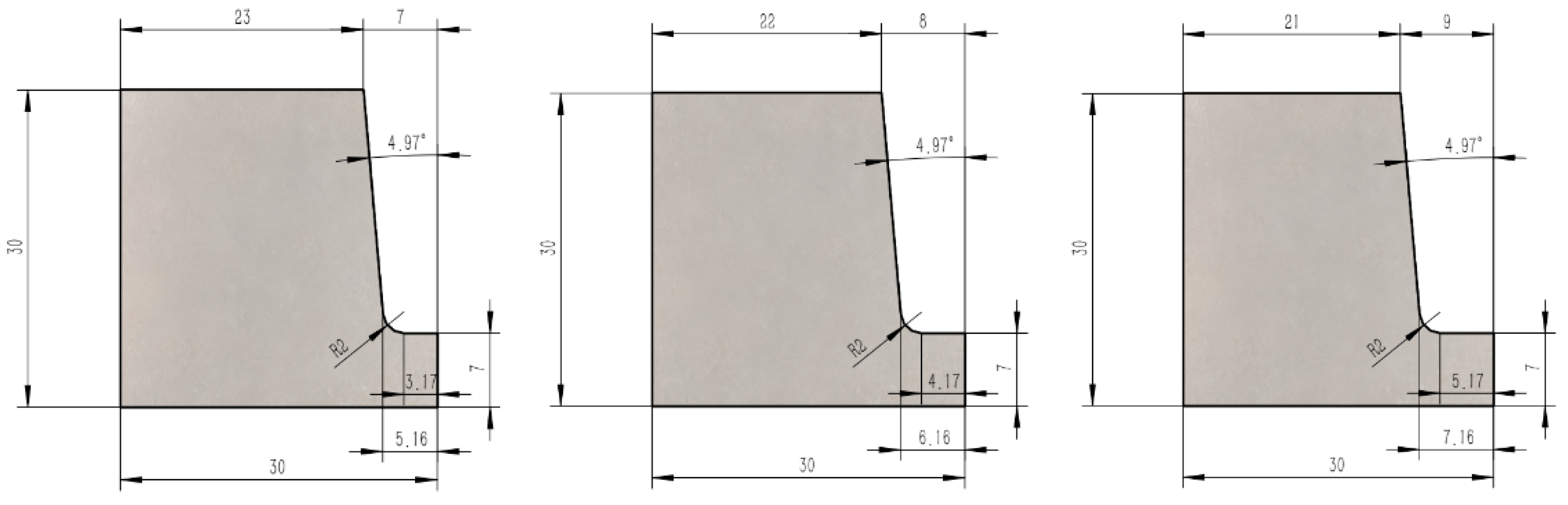
In order to quantify the relationship between filling sizes and processing parameters with different groove widths in relatively fewer experiments, a Box–Behnken design was chosen to prepare and analyze the results [19]. The parameters used and designed are given in Table 3 and Table 4. The pulse parameters and oscillation parameters are given in Table 5. The sizes and geometry of the grooves used in the Box–Behnken design are shown in Figure 2. The wire feed speed is marked as vfill, the welding speed is marked as vweld, the bottom width of the grooves is marked as bgroove, the filling height is marked as hfill and the width of the HAZ is marked as wHAZ.
Table 3.
Ranges of the parameters used in the Box–Behnken design.
Table 4.
Experimental parameters and responses in the Box–Behnken design.
Table 5.
Pulse parameters and oscillation parameters set in the machines.
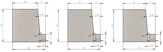
Figure 2.
Grooves used in the Box–Behnken design.
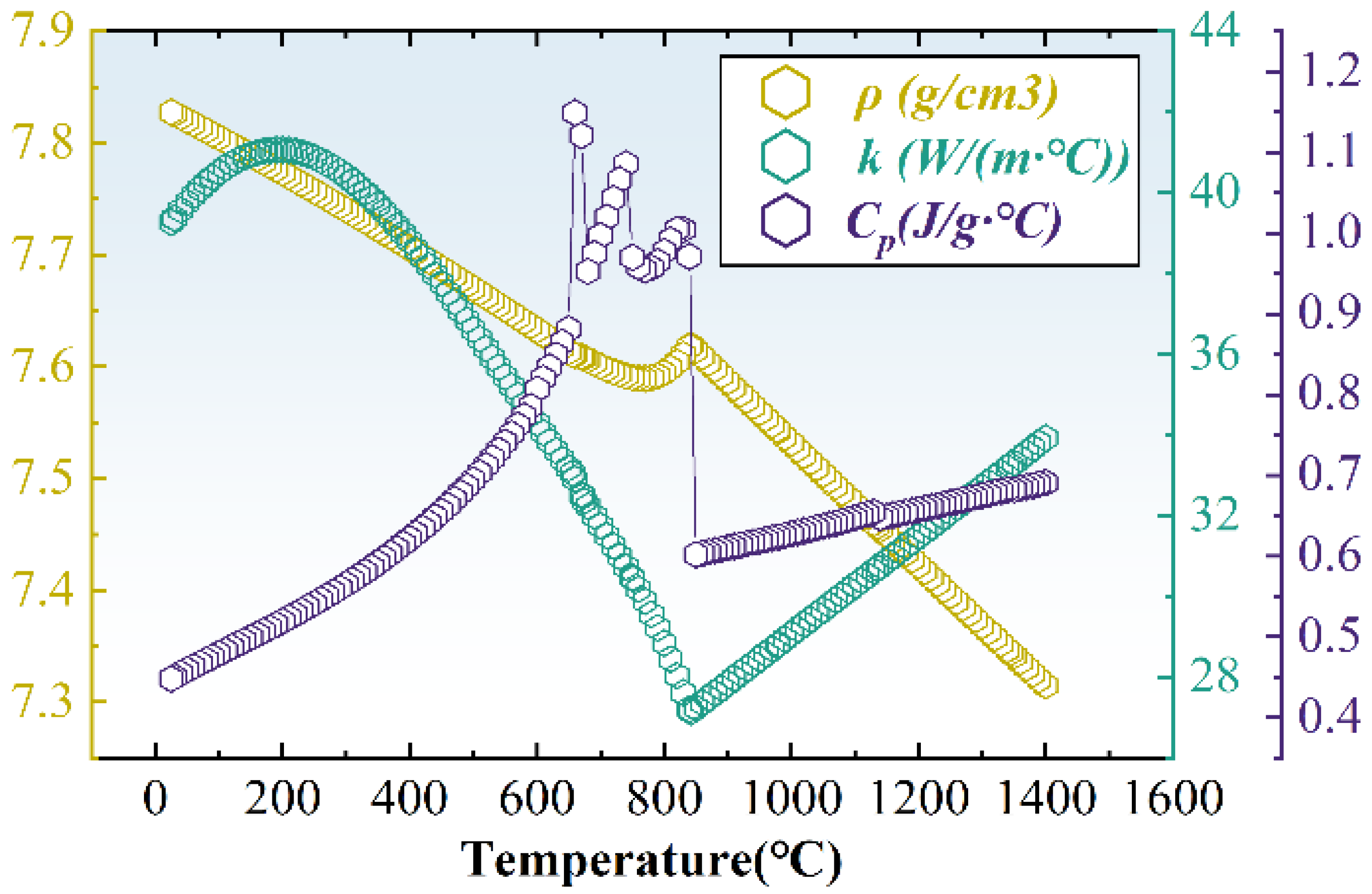
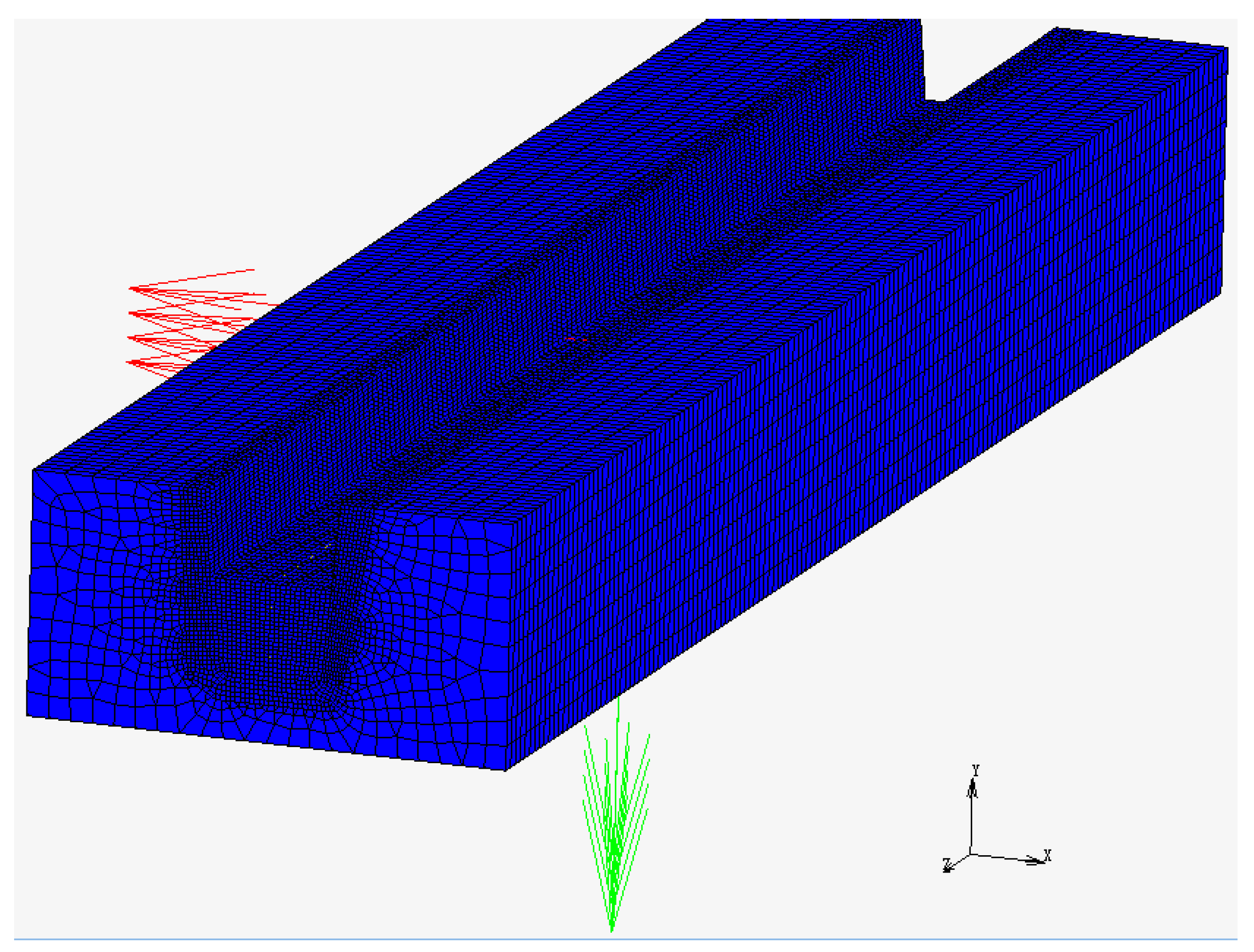
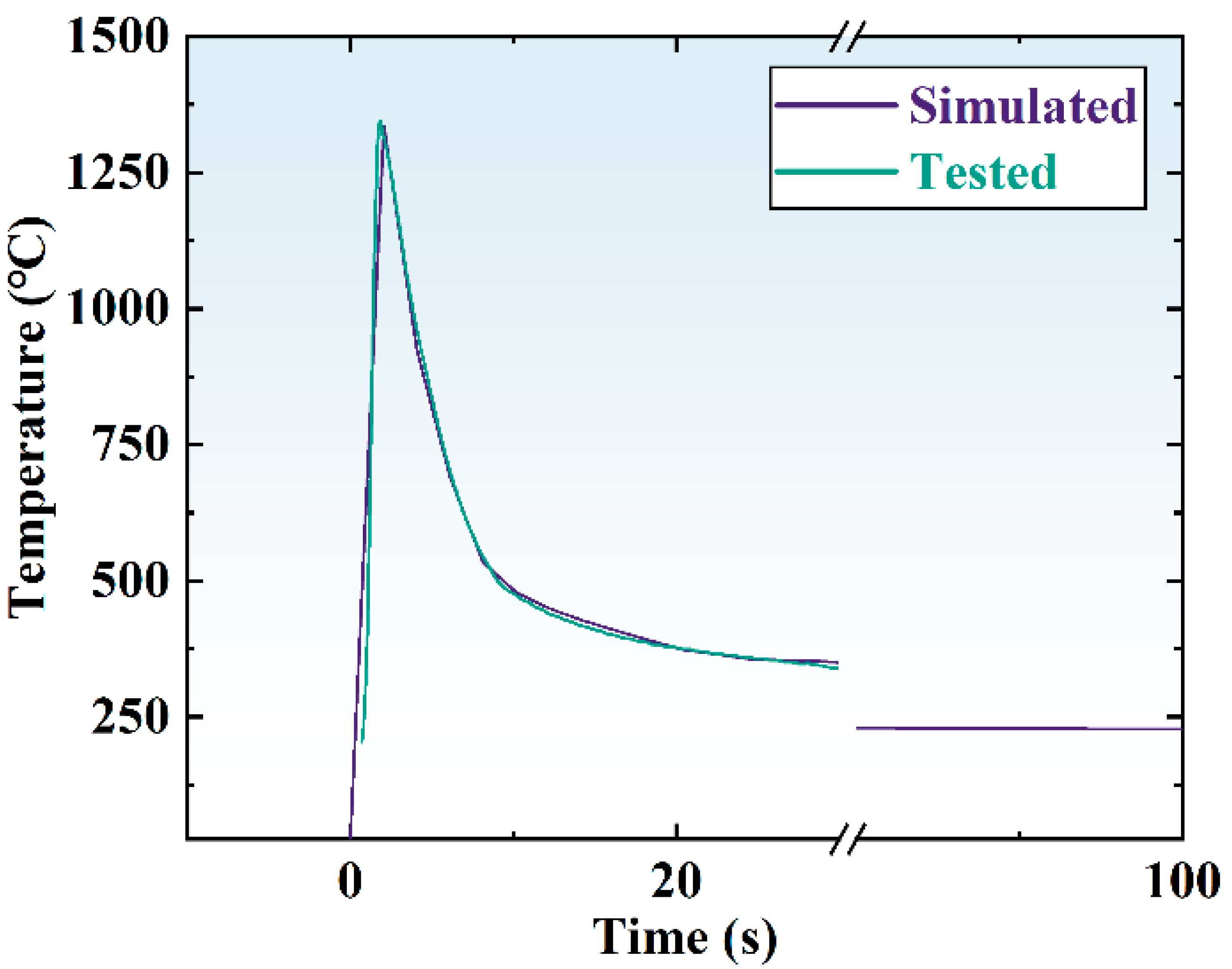
A finite element thermal model was used to analyze the thermal processes of the narrow gap GMA multilayer welding in three dimensions by MSC.Marc. The geometry of the cross-section of the calculated model was as shown in Figure 2. The bottom width of the grooves used for calculation was 12 mm and the length was 250 mm. Data of the material properties are given in Figure 3 and the meshed model is given in Figure 4. A test point in CGHAZ was chosen to assess the heat source. The assessment of the heat source is given in Figure 5. Faces except the sidewalls and the bottom were convection and radiation boundaries. The governing equation and the boundary conditions are given below. A double ellipsoid heat source was used, and the parameters used in the calculation are given in Table 6.
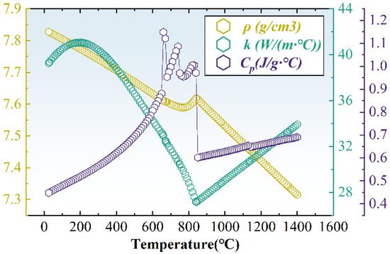
Figure 3.
Density, thermal conductivity and specific heat of the base metal.
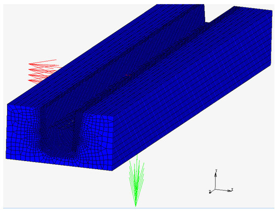
Figure 4.
Meshed model used in the simulation.
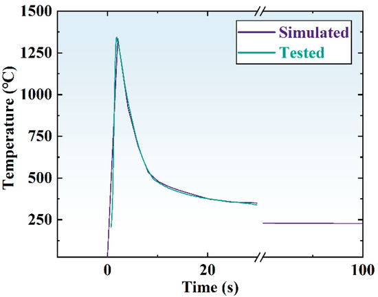
Figure 5.
Assessment of the heat source.
Table 6.
Heat source and material property parameters.
In Equations (1)–(5), ρ is the density of the metal used for calculation, λ is the thermal conductivity with the assumption of material isotropy, hc is the convective heat transfer coefficient, T0 is the initial temperature, U is the average voltage and I is the average current.
Specimens cut from the base metal with dimensions of 11 mm × 11 mm × 110 mm were used for thermal simulation testing using a Gleeble 3500 system. Each specimen underwent thermal simulation according to the thermal cycle calculated at the typical position.
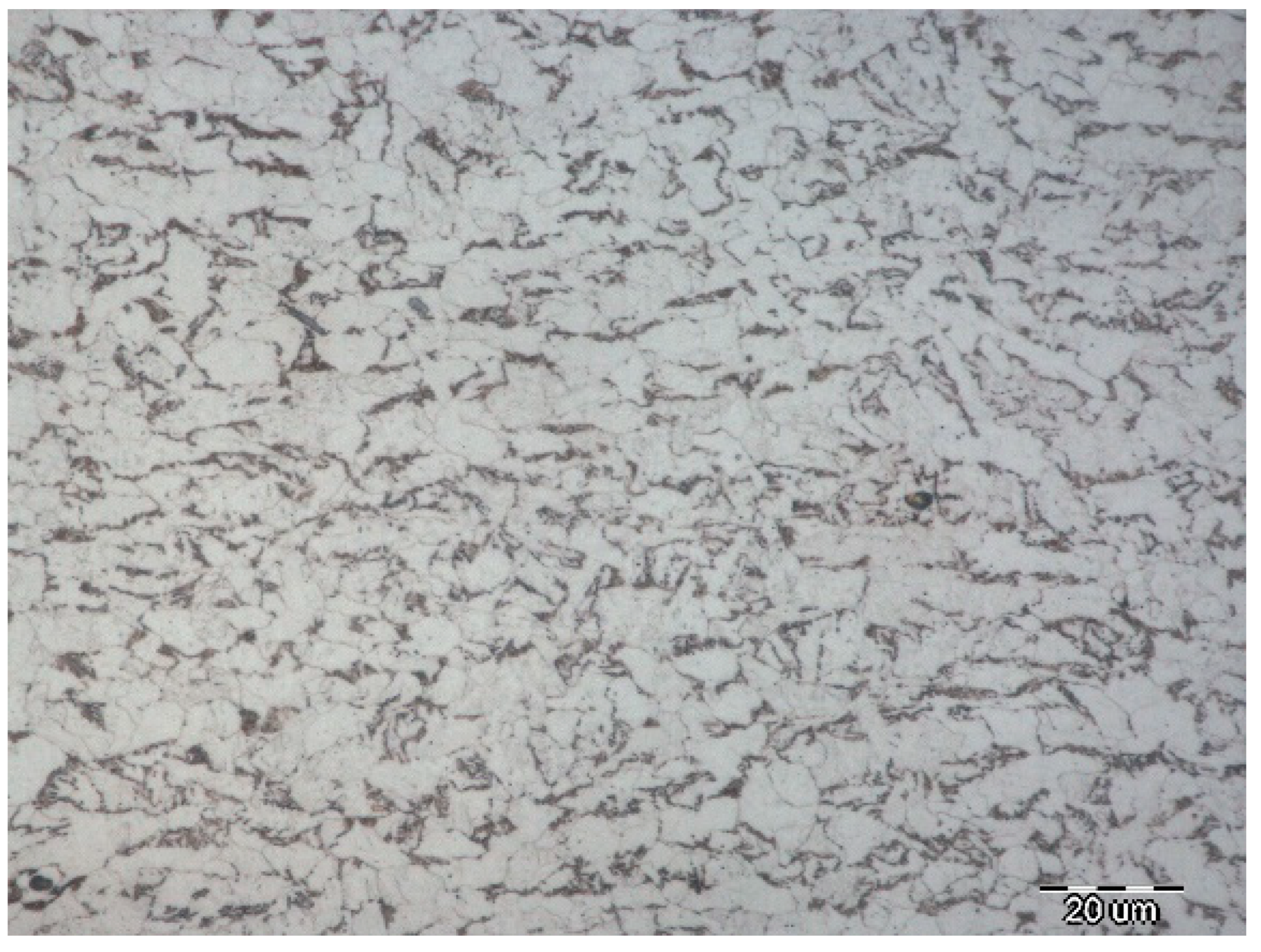
The microstructures of the base metal are shown in Figure 6. The microstructures of the base metal were quasi-polygonal ferrite (QF) and acicular ferrite (AF), with a small amount of retained austenite distributed in the grain boundaries.
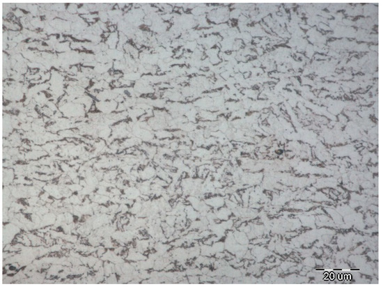
Figure 6.
Microstructures of the base metal (with a magnification of 1000).
3. Results and Discussion
The welding procedures were carried out with the parameters designed in Table 4, the responses of filling height and wHAZ were calculated to obtain Equations (6) and (7) and an ANOVA was performed. Goodness of fit details are given in Table 7. It is indicated that the two mathematical models were well suited to the prediction within the picked parameter ranges, which is convenient to estimate the size magnitudes of filling heights and widths of HAZs [21].
Table 7.
Goodness of fit.
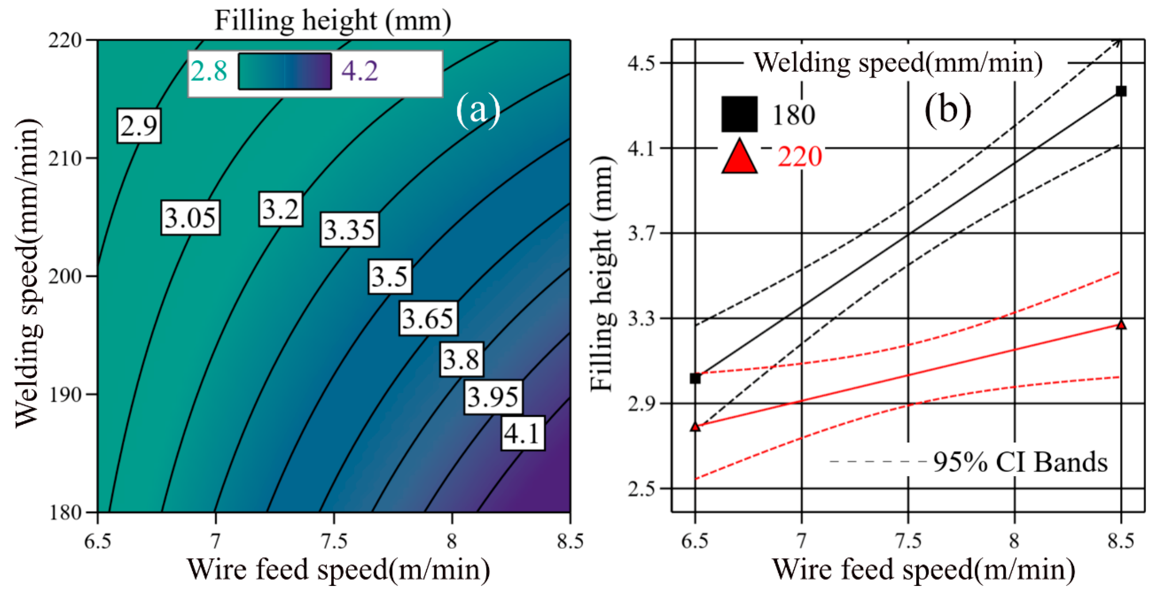
A 12-millimeter-width bgroove was picked to show the changes in filling height with various wire feed speeds and welding speeds. The effects of wire feed speed and welding speed interaction are given in Figure 7. According to Figure 7a, the filling height ranged from around 2.8 mm to 4.2 mm in the selected parameter regions. As the wire feed speed increased and the welding speed decreased, the density of the isopleth increased. Further and direct interaction is shown in Figure 7b. The increase in filling height with the wire feed speed at a welding speed of 220 mm/min appears to be significantly lower than that at a welding speed of 180 mm/min.
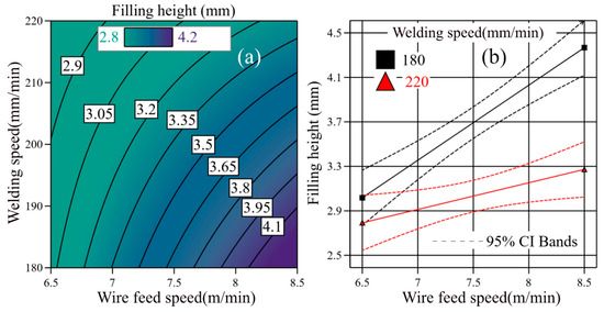
Figure 7.
Height of filling passes in a couple of 12-millimeter-width grooves: (a) filling height obtained by the calculated models; (b) interaction of welding speed and wire feed speed on the filling height.
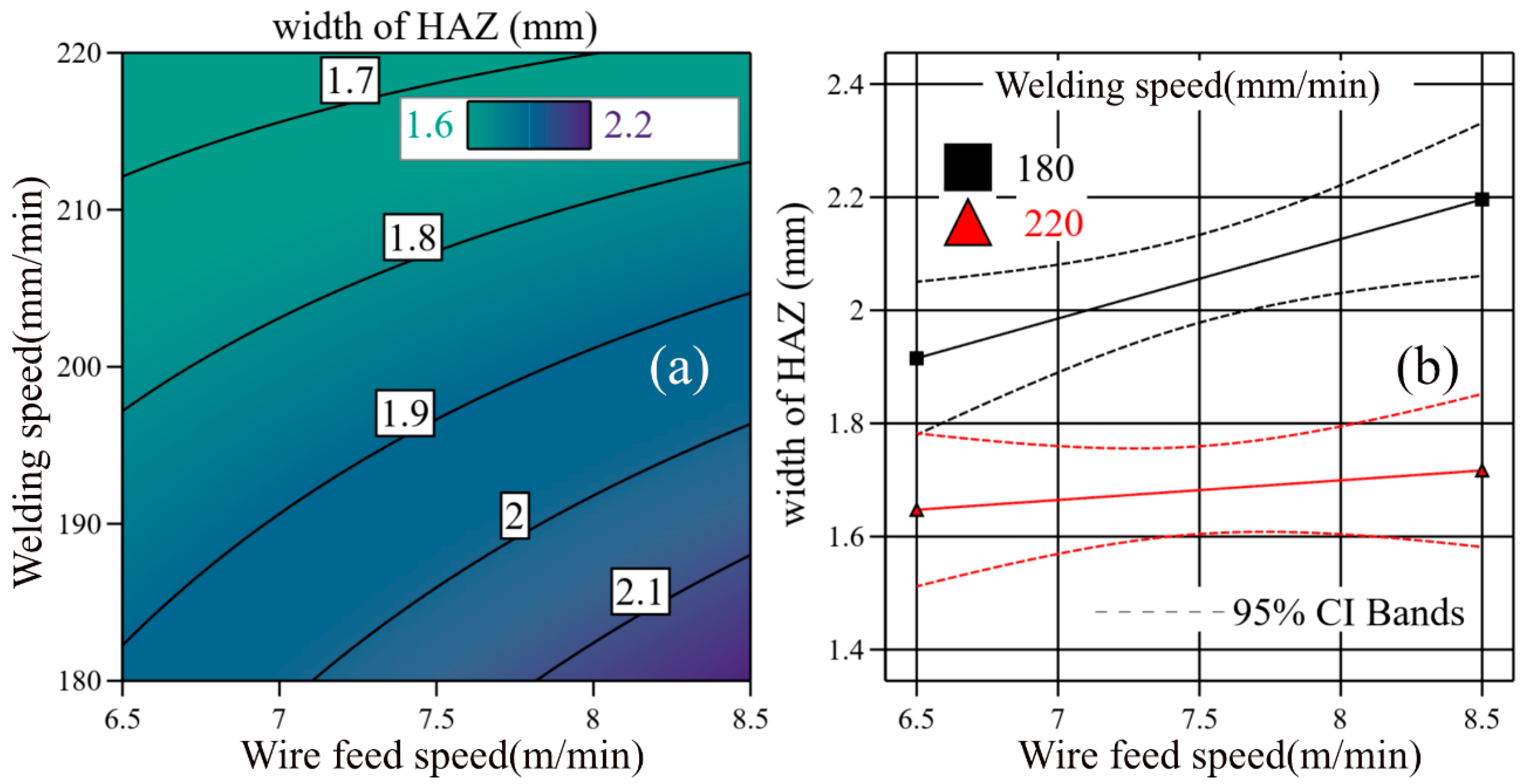
Similarly, the width of the HAZs is given by Figure 8. The width of the HAZs ranged from around 1.6 mm to 2.2 mm. As the welding speed increased, there was less influence of the wire feed speed on the width of the HAZs, while the filling height decreased as the welding speed increased at any wire feed speed within its range. According to Figure 7a and Figure 8a, the impact of welding speed on the isopleth curves appears to be more significant in Figure 8a, which indicates that the welding speed exerts more influence on the width of HAZs than the filling height does. Figure 7b directly shows the decline in the influence at different welding speeds.

Figure 8.
Size of heat-affected zones: (a) widths of HAZs obtained by the calculated models; (b) interaction of welding speed and wire feed speed on the width of the HAZs.
The penetration of a couple of 12-millimeter-width grooves is given in Table 8. The penetration ranged from around 1.7 mm to 1.9 mm with various parameters. It was found that a larger wire feed speed would not cause an increase in the penetration at a given welding speed. It is likely that the heat input depends on the voltages and the welding speed in a U-I pulsed mode, and the same peak voltage and pulsed wave were picked in all welding procedures, which would lead to less thermal efficiency in heating the base metal with a larger sum of filler metal.
Table 8.
Penetration in a 12-millimeter-width groove.
With the reference of the sizes above, the ranges of heat-affected areas among passes could be determined. In this study, the parameters given in Table 9 were picked to obtain the multilayer joints for observing the microstructures.
Table 9.
Parameters picked for microstructure observations.
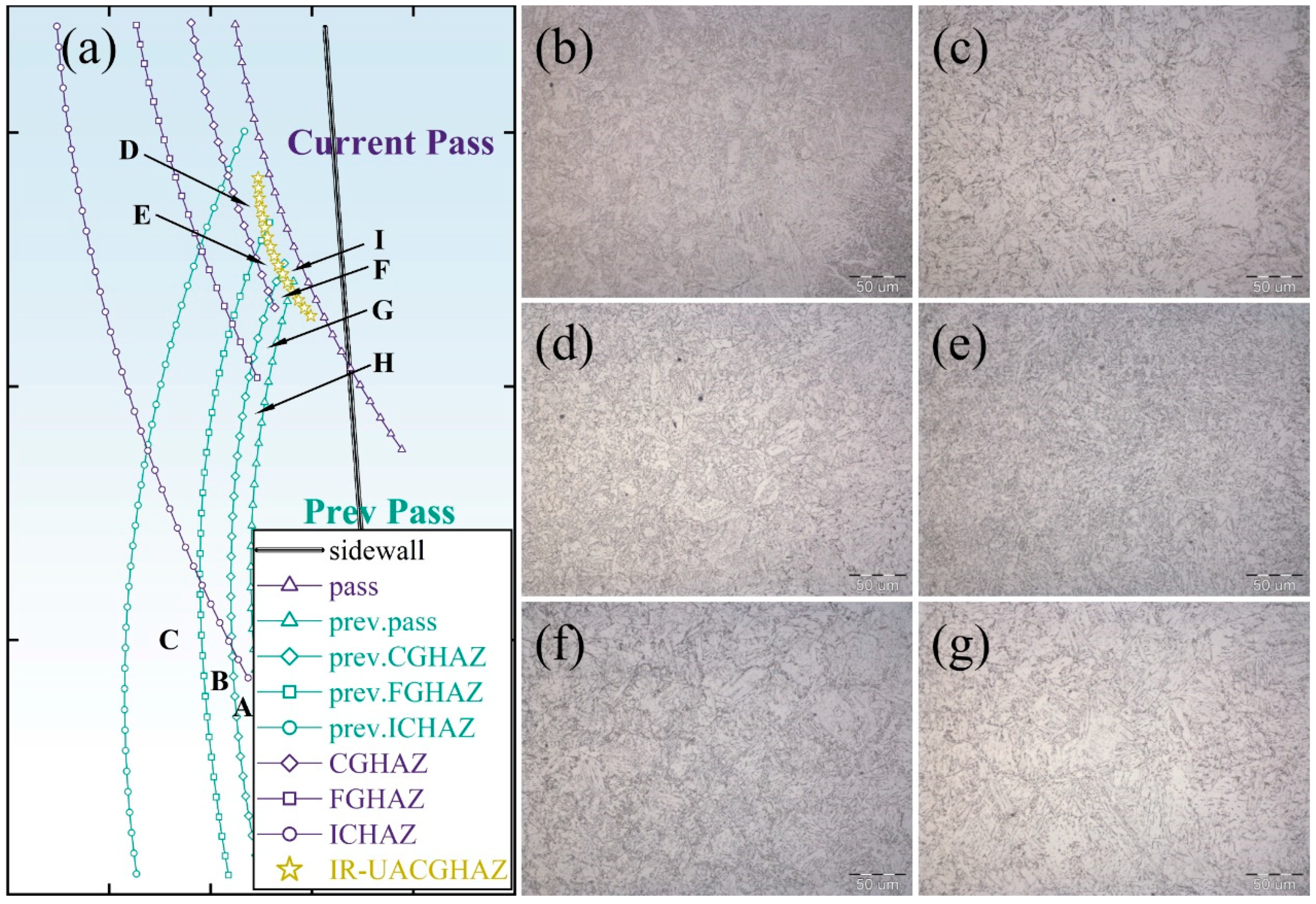
The filling height per pass was around 3.4 mm, the penetration was around 1.9 mm and the width of heat-affected zones was around 1.8 mm~1.9 mm. The filling height was close to the sum of the penetration and the width of heat-affected zones, which indicates that the transient phenomena caused by the current pass to the CG-HAZ of the previous pass would be entirely reserved. It is possible that the next pass could have heat effects with an austenitized procedure on the previous pass, but it is unlikely that further passes have thermal effects on the previous pass. Thus, the typical distribution of coarse grain heat-affected zones in a swing arc narrow gap GMA welded joint could be defined as the pattern given in Figure 9a. The microstructures are given in Figure 9.
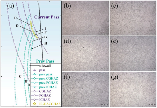
Figure 9.
Overlapping patterns of the coarse grain heat-affected zones and the microstructures at the typical zones (with a magnification of 500): (a) distribution of CG-HAZs; (b) A: CG-HAZ; (c) F: UACG-HAZ; (d) G: SCRCG-HAZ; (e) H: IRCG-HAZ, near to the reference curve FGHAZ; (f) H: IRCG-HAZ, far away from the reference curve FGHAZ; (g) I: IR-UACG-HAZ.
As shown in Figure 9a, the previous pass generated heat-affected zones marked as ‘prev.CGHAZ’, ‘prev.FGHAZ’ and ‘prev.ICHAZ’. Zone A is a CG-HAZ, zone B is an FG-HAZ and zone C is an IC-HAZ. The current pass also generated its own CG-HAZ, FG-HAZ and IC-HAZ marked as ‘CGHAZ’, ‘FGHAZ’ and ‘ICHAZ’, respectively. Zone F is a UACG-HAZ generated from the overlapping of ‘CGHAZ’ and ‘prev.CGHAZ’, zone G is an SCRCG-HAZ generated from the overlapping of ‘FGHAZ’ and ‘prev.CGHAZ’ and zone H is an IRCG-HAZ generated from the overlapping of ‘ICHAZ’ and ‘prev.CGHAZ’. Given that it is possible that the previous pass could be heat-affected by the next pass, an IR-UACG-HAZ reference curve was added within zone F, in which zone I is an IR-UACG-HAZ generated by the overlapping of the UACG-HAZ and the IC-HAZ of the next pass. The microstructures of the CG-HAZ, UACG-HAZ, SCRCG-HAZ, IRCG-HAZ and IR-UACG-HAZ are shown in Figure 9b–g. There was mainly lath bainite growing from the prior austenite grain boundaries to the grain interior and a small amount of acicular ferrite. In the UACG-HAZ shown in Figure 9c, the amount of acicular ferrite slightly increased. The size of the prior austenite grain also slightly increased, and laths across the entire prior austenite grain appeared. In Figure 9d, there is lath bainite and granular bainite in the SCRCG-HAZ. The sizes of the prior austenite grains significantly decreased, and the morphological features of the bainitic ferrite inside the grains transferred from short laths to acicular ferrite and quasi-polygonal ferrite. Lath bainite also tended to transfer to granular bainite. The microstructures in the IRCG-HAZ are shown in Figure 9e,f. Two different appearances were observed in the IRCG-HAZ. Figure 9e is nearer to the reference curve ‘FGHAZ’ than Figure 9f is. There is mainly granular bainite, acicular ferrite and a small amount of quasi-polygonal ferrite in Figure 9e. A large sum of tiny secondary ferrite and austenite decomposition products appeared along the prior austenite grain boundaries and grain interior, and the microstructures were similar to those in the CG-HAZ, as is shown in Figure 9f. Figure 9g shows the microstructures of the IR-UACG-HAZ. The microstructures were similar to those in the UACG-HAZ, except for the small amount of tiny secondary ferrite and austenite decomposition products along the prior austenite boundaries.
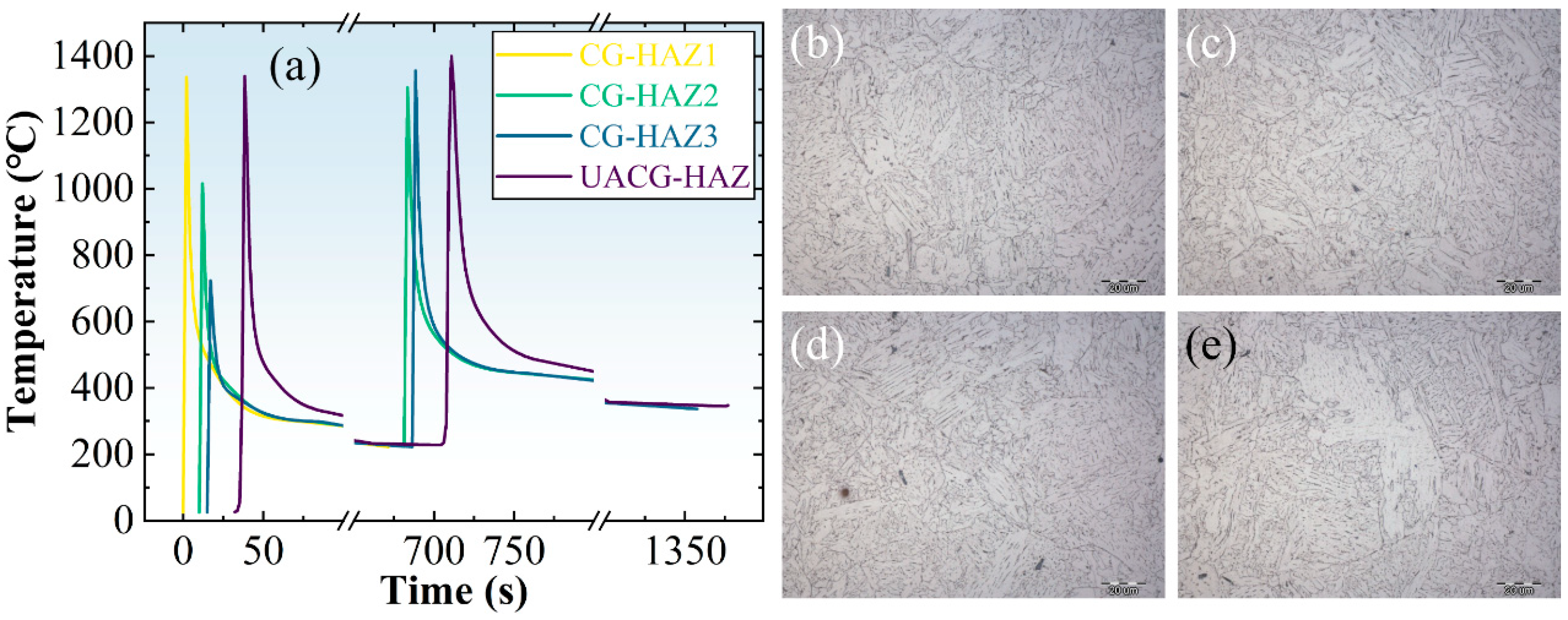
Thermal processes and thermal simulations were carried out for further investigation of the microstructure distribution and transformation. The thermal cycles and microstructures of zones whose second thermal cycle was a CG-HAZ thermal process are given in Figure 10. Zone A, zone E, zone D and zone F in Figure 9a are marked as ‘CG-HAZ1′, ‘CG-HAZ2′, ‘CG-HAZ3′ and ‘UACG-HAZ’ in Figure 10a, respectively. It was realized that the microstructures in the CG-HAZs showed similar morphological features. Although the peak temperatures in the first thermal cycle are different in Figure 10b–d, there are mainly lath bainites within the prior austenite grains, and the sizes of the prior austenite grains were similar among the CG-HAZs and the UACG-HAZ, which is well applied to the features in the welded CG-HAZs.
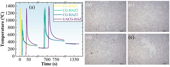
Figure 10.
Thermal processes in zones with CG-HAZ processes during the last austenitized cycles and the thermal simulated microstructures (with a magnification of 1000): (a) thermal cycles calculated for thermal simulation in CG-HAZs; (b) CG-HAZ1; (c) CG-HAZ2; (d) CG-HAZ3; (e) UACG-HAZ.
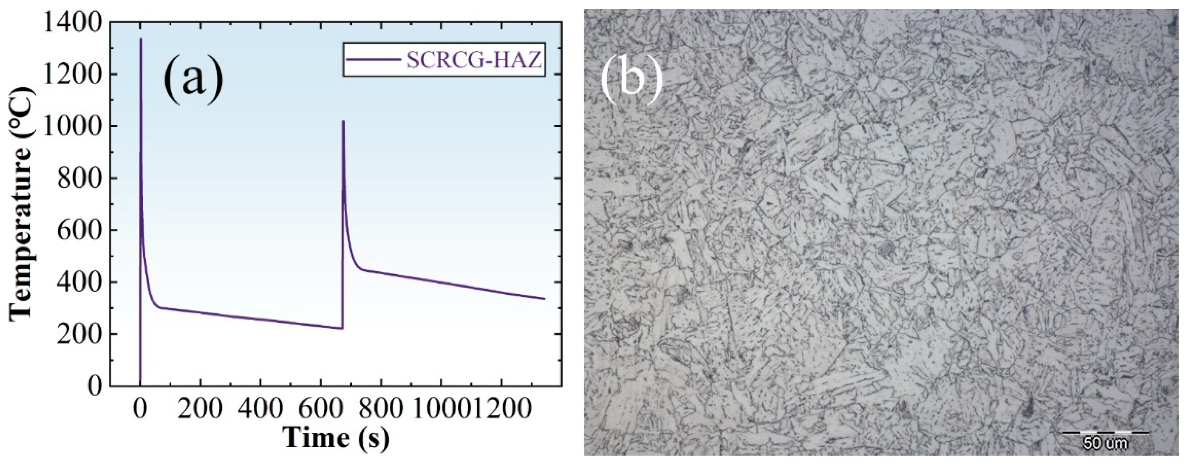
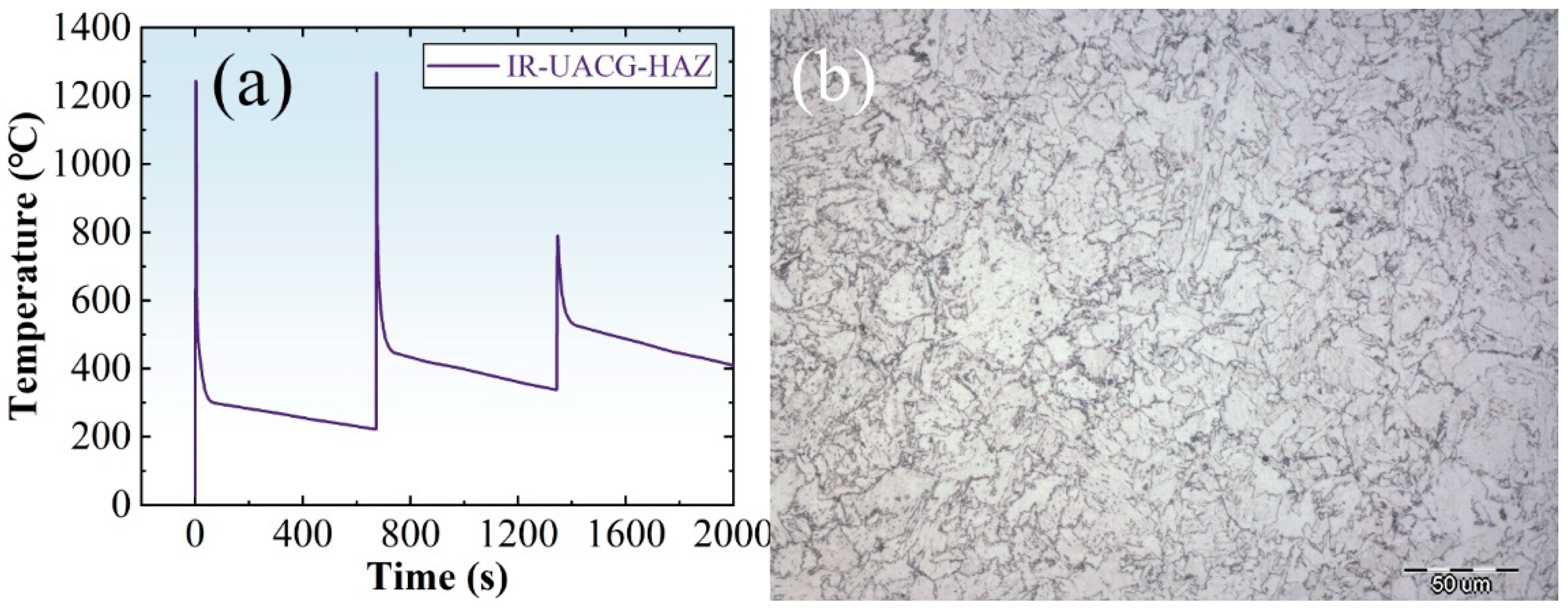
The thermal cycles and microstructures of the SCRCG-HAZ, IRCG-HAZ and IR-UACG-HAZ are given in Figure 11, Figure 12 and Figure 13. There was less acicular ferrite in the thermal simulated SCRCG-HAZ than in the welded SCRCG-HAZ. However, the size of the prior austenite grains appeared to be of the same magnitude as the size of the grains in the welded SCRCG-HAZ, and the microstructures were lath bainite and granular bainite. Prior austenite grain boundaries were entirely invisible in the simulated IRCG-HAZ, and the thermal simulated microstructures were almost granular bainite and a small amount of acicular ferrite, which might be applied to the features in Figure 9f. The thermal simulated IR-UACG-HAZ seems not well applied to the features in Figure 9g. That means there is only the feature that a few austenite decomposition products were distributed along the prior austenite grain boundaries retained. Long lath bainites did not appear, with massive textures instead.
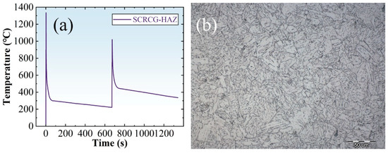
Figure 11.
Thermal process of SCRCG-HAZ and the thermal simulation microstructures (with a magnification of 500): (a) thermal cycles calculated for thermal simulation of SCRCG-HAZ; (b) microstructures of thermal simulated SCRCG-HAZ.
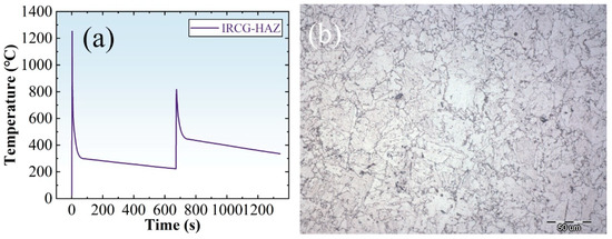
Figure 12.
Thermal processes of IRCG-HAZ and the thermal simulation microstructures (with a magnification of 500): (a) thermal cycles calculated for thermal simulation of IRCG-HAZ; (b) microstructures of thermal simulated IRCG-HAZ.
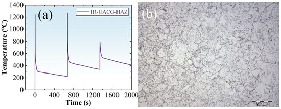
Figure 13.
Thermal process of incomplete recrystallized UACG-HAZ and the thermal simulation microstructures (with a magnification of 500): (a) thermal cycles; (b) microstructures of the thermal simulation zone.
For further discussion, CCT curves of the base metal and the typical cooling times in the last thermal cycle of each thermal simulation process were calculated and are given by Figure 14 and Table 10. The cooling time from 800 °C to 600 ℃ is marked as t8/6, the cooling time from 600 ℃ to 500 ℃ is marked as t6/5, the cooling time from 500 ℃ to Ms is marked as t500/Ms, the peak temperature in the last austenitized process is marked as Tp-end and the cooling time from the peak temperature to 800 ℃ is marked as tp/8. According to Figure 14 and Table 10, it is indicated that all thermal simulated microstructures were bainite and ferrite. The temperature range of ferrite transformation is around 600 ℃~750 ℃, and the ending temperature of bainite transformation is around 463 ℃. The cooling time in the undercooled austenite decomposition procedure was significantly higher in zones twice austenitized, especially in the UACG-HAZ, compared to those with a single austenitized thermal cycle. The tp/8 showed the same pattern. A long tp/8 with a long t8/6 and t6/5 could lead to a larger prior austenite grain size because of the retention in the fast-growing temperature ranges and an increase in AF as well as the length of the laths because of the relatively long staying time of t500/Ms and t6/5 in addition to a relatively larger grain size for the nucleation of intragranular ferrite. There was little difference in t8/6 and t6/5 between CG-HAZ2 and CG-HAZ3. Thus, more AF and longer laths could be found in CG-HAZ2, CG-HAZ3 and UACG-HAZ than in CG-HAZ1.
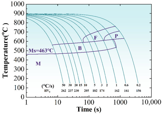
Figure 14.
CCT curves of the base metal.
Table 10.
Cooling time of typical temperature ranges in the thermal simulation processes.
The t8/6 in the SCRCG-HAZ was larger than that in CG-HAZ2 and CG-HAZ3 and smaller than that in the IRCG-HAZ. In the IR-UACG-HAZ, the cooling time in every typical temperature range of bainites transformation severely increased in the third austenitized thermal cycle. Since the prior austenite grain size was smaller in the SCRCG-HAZ, massive textures may have been competitive in the cooling procedure of 600 ℃~500 ℃, with a larger t8/6 compared to the CG-HAZs. The t500/Ms of the SCRCG-HAZ also seemed long enough to generate an amount of AF. Thus, the microstructures in the SCRCG-HAZ mainly appeared to be massive textures and AF together with small lath bainite across the prior austenite grains [22]. In the IRCG-HAZ, the t8/6 was close to that of the UACG-HAZ. However, the staying time above Ac3 was so short that the austenite grains had no chance to grow. Additionally, the composition homogenization process was not entirely developed. Therefore, the grain sizes of the prior austenite appeared to have a non-uniform distribution with massive textures and quasi-polygonal ferrite inside and a large amount of tiny secondary austenite decomposition along the grain boundaries. Similar patterns could also be observed in the IR-UACG-HAZ.
4. Conclusions
- With the given parameters in this study, the size magnitude of the filling height and width of HAZs could be defined with a range of 2.8~4.2 mm and 1.6~2.2 mm, respectively, in grooves with a bottom width of 12 mm when the welding speed was around 180~220 mm/min and the wire feed speed was around 6.5~8.5 m/min. The welding speed had a more significant influence on the width of the HAZ than on the filling height.
- The overlapping features of HAZs among passes in a typical swing arc narrow gap GMA welded joint were defined. The CG-HAZ of a single pass could only be heat-affected by the next two passes.
- The distribution patterns of the CG-HAZs were defined and arranged as a CG-HAZ, an IRCG-HAZ, an SCRCG-HAZ, a UACG-HAZ and an IR-UACG-HAZ from a single heat-affected pass to the third pass.
- The microstructures in the CG-HAZ and UACG-HAZ were lath bainite and acicular ferrite, the microstructures in the SCRCG-HAZ were short lath bainite and granular bainite and the microstructures in the IRCG-HAZ and UACG-HAZ were massive textures and secondary austenite decomposition products.
Author Contributions
Conceptualization, X.C. and S.L.; formal analysis, Z.N. and B.D.; resources, F.H.; data curation, Z.N., B.D. and F.H.; writing—original draft, Z.N.; writing—review and editing, X.C.; supervision, S.L.; funding acquisition, X.C. All authors have read and agreed to the published version of the manuscript.
Funding
This work was supported by the National Natural Science Foundation of China (grant number 51905128) and the Open Project Program of the State Key Laboratory of Metal Material for Marine Equipment and Application (grant number SKLMEA-K202005).
Institutional Review Board Statement
Not applicable.
Informed Consent Statement
Not applicable.
Data Availability Statement
Data are not available since the data in this study will be used in our current research works.
Acknowledgments
The FEM analysis work was guided and supported by Dong B.
Conflicts of Interest
The authors declare no conflict of interest.
References
- Mandal, N.R. Ship Construction and Welding; Springer: Singapore, 2017. [Google Scholar]
- Dehghani, A.; Aslani, F. A review on defects in steel offshore structures and developed strengthening techniques. Structure 2019, 20, 635–657. [Google Scholar] [CrossRef]
- Tümer, M.; Schneider-Bröskamp, C.; Enzinger, N. Fusion welding of ultra-high strength structural steels—A review. J. Manuf. Process. 2022, 82, 203–229. [Google Scholar] [CrossRef]
- Deng, W.; Qin, X. Development of High Heat Input Welding Offshore Steel as Normalized Condition. In HSLA Steels 2015, Microalloying 2015 & Offshore Engineering Steels 2015; Wiley: Hoboken, NJ, USA, 2015. [Google Scholar]
- Shi, M.H.; Yuan, X.G.; Huang, H.J.; Zhang, S. Effect of Zr Addition on the Microstructure and Toughness of Coarse-Grained Heat-Affected Zone with High-Heat Input Welding Thermal Cycle in Low-Carbon Steel. J. Mater. Eng. Perform. 2017, 26, 3160–3168. [Google Scholar] [CrossRef]
- Shi, Z.; Wang, R.; Wang, Q.; Su, H.; Chai, F.; Yang, C. Microstructures and Continuous Cooling Transformation of CGHAZ in E36 Class V-N-Ti, V-Ti and Nb-Ti Shipbuilding Steels. In HSLA Steels 2015, Microalloying 2015 & Offshore Engineering Steels 2015; Springer: Berlin/Heidelberg, Germany, 2016. [Google Scholar]
- Shi, Y.; Han, Z. Effect of weld thermal cycle on microstructure and fracture toughness of simulated heat-affected zone for a 800 MPa grade high strength low alloy steel. J. Mater. Process. Technol. 2008, 207, 30–39. [Google Scholar] [CrossRef]
- Buchmayr, B. Thermomechanical Treatment of Steels—A Real Disruptive Technology Since Decades. Steel Res. Int. 2017, 88, 1700182. [Google Scholar] [CrossRef]
- Mu, W.; Jönsson, P.G.; Nakajima, K. Recent Aspects on the Effect of Inclusion Characteristics on the Intragranular Ferrite Formation in Low Alloy Steels: A Review. High Temp. Mater. Process. 2017, 36, 309–325. [Google Scholar] [CrossRef]
- Seo, K.; Ryoo, H.; Kim, H.J.; Park, C.G.; Lee, C. Local variation of impact toughness in tandem electro-gas welded joint. Weld. World 2020, 64, 457–465. [Google Scholar] [CrossRef]
- Sha, Q.; Sun, Z. Grain growth behavior of coarse-grained austenite in a Nb–V–Ti microalloyed steel. Mater. Sci. Eng. A 2009, 523, 77–84. [Google Scholar] [CrossRef]
- Medina, S.F.; Chapa, M.; Valles, P. Influence of Ti and N contents on austenite grain control and precipitate size in structural steels. ISIJ Int. 1999, 39, 930–936. [Google Scholar] [CrossRef]
- Liu, Y.; Li, G.; Wan, X.; Zhang, X.; Shen, Y.; Wu, K. Toughness improvement by Zr addition in the simulated coarse-grained heat-affected zone of high-strength low-alloy steels. Ironmak. Steelmak. 2019, 46, 113–123. [Google Scholar] [CrossRef]
- Li, X.; Zhang, T.; Min, Y.; Liu, C.; Jiang, M. Effect of magnesium addition in low-carbon steel part 1: Behaviour of austenite grain growth. Ironmak. Steelmak. 2019, 46, 292–300. [Google Scholar] [CrossRef]
- Guo, N.; Wang, M.; Guo, W.; Yu, J.; Feng, J. Effect of rotating arc process on molten pool control in horizontal welding. Sci. Technol. Weld. Join. 2014, 19, 385–391. [Google Scholar] [CrossRef]
- Xu, W.; Lin, S.; Fan, C.; Zhuo, X.; Yang, C. Statistical modelling of weld bead geometry in oscillating arc narrow gap all-position GMA welding. Int. J. Adv. Technol. 2014, 72, 1705–1716. [Google Scholar] [CrossRef]
- Xu, W.; Lin, S.; Fan, C.; Yang, C. Evaluation on microstructure and mechanical properties of high-strength low-alloy steel joints with oscillating arc narrow gap GMA welding. Int. J. Adv. Technol. 2014, 75, 1439–1446. [Google Scholar] [CrossRef]
- Cai, X.; Fan, C.; Lin, S.; Ji, X.; Yang, C.; Guo, W. Effects of shielding gas composition on arc properties and wire melting characteristics in narrow-gap MAG welding. J. Mater. Process. Technol. 2017, 244, 225–230. [Google Scholar] [CrossRef]
- Ferreira, S.L.C.; Bruns, R.E.; Ferreira, H.S.; Matos, G.D.; David, J.M.; Brandao, G.C.; Silva, E.G.P.D.; Portugal, L.A.; Reis, P.S.D.; Souza, A.S. Box-Behnken design: An alternative for the optimization of analytical methods. Anal. Chim. Acta 2007, 597, 179–186. [Google Scholar] [CrossRef] [PubMed]
- Ngo, T.T.; Wang, C.C.; Huang, J.H.; Than, V.T. Estimating heat generation and welding temperature for Gas Metal Arc Welding process. Appl. Therm. Eng. 2019, 160, 114056. [Google Scholar] [CrossRef]
- Gotelli, N.J.; Ellison, A.M. A Primer of Ecological Statistics; Sinauer Associates Sunderland: Oxford, UK, 2004. [Google Scholar]
- Zhao, H.; Palmiere, E.J. Effect of austenite grain size on acicular ferrite transformation in a HSLA steel. Mater. Charact. 2018, 145, 479–489. [Google Scholar] [CrossRef]


Disclaimer/Publisher’s Note: The statements, opinions and data contained in all publications are solely those of the individual author(s) and contributor(s) and not of MDPI and/or the editor(s). MDPI and/or the editor(s) disclaim responsibility for any injury to people or property resulting from any ideas, methods, instructions or products referred to in the content. |
© 2022 by the authors. Licensee MDPI, Basel, Switzerland. This article is an open access article distributed under the terms and conditions of the Creative Commons Attribution (CC BY) license (https://creativecommons.org/licenses/by/4.0/).