1. Introduction
Despite quite a large number of scientific studies in the field of studying radiation damage and the kinetics of radiation defects in structural materials, including various types of ceramics, interest in this area has not weakened, and has only increased in the last few years [
1,
2,
3]. This increased interest in this area of research is due to several factors.
First, with the adoption of the EuroFusion concept in the development of nuclear and fusion power, the world pays greater attention to studying the properties of new types of structural materials included in the list of candidates for new generation reactors, including fusion reactors [
4,
5]. It should be noted that ceramics based on oxides (MgO, Al
2O
3, ZrO
2, BeO), carbides (SiC, TaC, TiC), and nitrides (AlN, BN, Si
3N
4) play an important role in this list [
6,
7,
8,
9,
10]. Interest in this class of materials is due to the fact that they have a high melting point, strength, and mechanical resistance to external influences, which makes them one of the promising materials for high-temperature nuclear reactors, as well as thermonuclear reactors.
Secondly, the development of accelerator technology over the past few decades has opened up new opportunities for research on modeling radiation damage processes, as well as irradiation conditions that are closest to real effects of background radiation and fission fragments in nuclear reactors [
11,
12,
13]. This, in turn, made it possible to obtain a number of unique fundamental data on the mechanisms of radiation damage, the resistance of materials to swelling and embrittlement processes, as well as the refinement of critical doses that cause partial or complete destruction of materials [
14,
15]. Additionally, the use of heavy ion accelerators for simulation of the radiation damage effects, due to the absence of the effect of accumulation of residual radiation by the irradiated material, made it possible to study irradiated samples immediately after irradiation, in contrast to reactor tests. This made it possible to eliminate the effects associated with relaxation processes during long-term exposure of irradiated samples in reactors, and also made it possible to conduct studies with various conditions and radiation doses, which is quite difficult in the case of reactor tests. However, despite the large number of positive effects of using heavy ion accelerators for such experiments, it is necessary to take into account, in a comparative analysis of irradiation experiments, the fact of the maximum penetration depth of ions, as well as the rate of dose increase by irradiated materials [
16,
17]. In the case of reactor tests, the radiation dose is accumulated over a rather long time, sometimes calculated in years. At the same time, the use of heavy ion accelerators for modeling radiation damage in materials makes it possible to carry out such experiments several times faster.
Thirdly, in the last few years, special attention has been paid to the development and refinement of various fundamental models of radiation damage, the main purpose of which is to create a unified approach for describing the observed effects, as well as a physical explanation and interpretation of the consequences of radiation damage to materials [
18,
19,
20]. The concept of most radiation damage models is based on the fact that the energy of incident particles is transferred to the electronic and nuclear subsystems of the target, followed by the transformation of kinetic energy into thermal energy and, as a result, the initialization of processes associated with thermal effects in the structure due to the creation of a temperature gradient in small local areas [
21,
22]. In most cases, the use of such an interpretation of the mechanisms of radiation damage makes it possible to describe the observed effects with high accuracy, the formation of dislocation damage, the recrystallization effects, or the formation of amorphous inclusions. However, in the case of irradiation with low-energy ions, for which the processes of interaction of incident ions with the electronic and nuclear subsystems are equally probable, in contrast to heavy ions, for which the interactions of ions with the electronic subsystem are dominant, these models are not always applicable [
23,
24,
25]. In the case of irradiation with low-energy ions, it should also be taken into account that the main changes occur in a very thin near-surface layer, the size of which can be only a few hundred nanometers. In this case, the influence of surface effects associated with the accumulation of radiation damage near the surface and subsequent destruction of the damaged layer as a result of embrittlement, formation of microcracks, or partial sputtering of the surface cannot be ruled out [
26,
27].
Additionally, quite a lot of questions remain concerning the description of the kinetics and mechanisms of radiation damage caused by the accumulation of helium in the structure of the near-surface layer, which can occur in the case of high-temperature nuclear reactors and thermonuclear reactors, both as a result of transmutation reactions and upon interaction with coolants [
28,
29,
30]. In this regard, it is necessary to have a clear understanding of the processes that occur during the accumulation of helium, as well as the consequences they have on changes in the structural, strength, or mechanical properties of structural materials. In the last few years, much attention has been paid to the study of the mechanisms of helium swelling, as well as the conditions and critical doses under which the formation of helium bubbles in the structure is observed, their further evolution, and the consequences they cause [
31,
32,
33]. At the same time, special attention is paid to this issue when studying these processes of radiation damage and helium swelling in high-temperature ceramics, the interest in which, as mentioned above, is due to the possibility of using them as structural materials for new generation reactors [
34,
35]. The basis of this interest is several factors associated with differences in the mechanisms of helium accumulation in the structure for ceramics and steels and alloys, structural features of ceramics, types of bonds, as well as mechanical and strength properties of materials. In this regard, much attention has recently been paid to works and studies aimed at studying the mechanisms of radiation damage during helium swelling and embrittlement.
The purpose of this work is to study the processes of change in the structural and mechanical properties of SiC ceramics exposed to low-energy He
2+ ions with fluence characteristics of the initialization of gaseous swelling and embrittlement processes. The relevance and novelty of this study is in the systematic analysis of changes in structural parameters, as well as the assessment of the contributions of various mechanisms of radiation damage to the degradation of the structure of the near-surface irradiated layer, depending on the concentration of radiation damage and implanted helium. Polycrystalline SiC ceramics of a hexagonal type of crystal structure, which have a number of unique physicochemical, mechanical and strength properties, which make them promising for use as the basis for structural materials of a new generation of nuclear reactors, were chosen as the object of study. Interest in these types of ceramics in the field of nuclear materials science and reactor engineering is due to the prospects of using them as the basis for a three-structural isotropic coating (TRISO) of new generation nuclear fuel elements for high-temperature nuclear reactors and fusion reactors, as materials for the first wall, as well as the manufacture of containers for long-term storage of spent nuclear fuel and its disposal [
36,
37,
38,
39,
40]. The applicability of SiC ceramics in these areas is due to their high mechanical strength, hardness, resistance to thermal shocks, wear resistance during operation at elevated temperatures and corrosion, low thermal expansion coefficient and high thermal stability, as well as the stability of geometric characteristics as a result of external influences.
2. Experimental Part
Polycrystalline SiC ceramics of the hexagonal type were chosen as the samples under study.
The processes of helium swelling of the near-surface layer of SiC ceramics depending on the irradiation dose were simulated using low-energy beams of He
2+ ions with an energy of 40 keV. Irradiation fluences ranged from 10
15 to 5 × 10
17 ion/cm
2. Irradiation was carried out at the heavy ion accelerator DC-60 (INP, Nur-Sultan, Kazakhstan), located on the basis of the Institute of Nuclear Physics of the Ministry of Energy of the Republic of Kazakhstan. Irradiation was carried out at room temperature of the target, which was maintained by placing the samples on water-cooled holders, which made it possible to maintain a constant temperature during the entire irradiation time. Calculations of energy losses, as well as the maximum ion path length and the thickness of the damaged layer, were carried out using the SRIM Pro 2013 [
41] program code and the Kinchin-Pease model.
Table 1 presents the results of calculations performed taking into account the target density (3.2 g/cm
3). The density was determined by the X-ray diffraction method, taking into account changes in structural parameters and crystal lattice volume.
According to the calculated data, the maximum thickness of the damaged layer is no more than 300 nm. As it is known, in the case of irradiation with low-energy ions, the contribution to radiation damage is made by the energy losses of ions during interaction with nuclei and electron shells. As can be seen from the calculated data, the energy losses in the case of irradiation with He2+ ions have the same order of magnitude, which indicates an equiprobable contribution to structural changes and defect formation processes in the damaged layer.
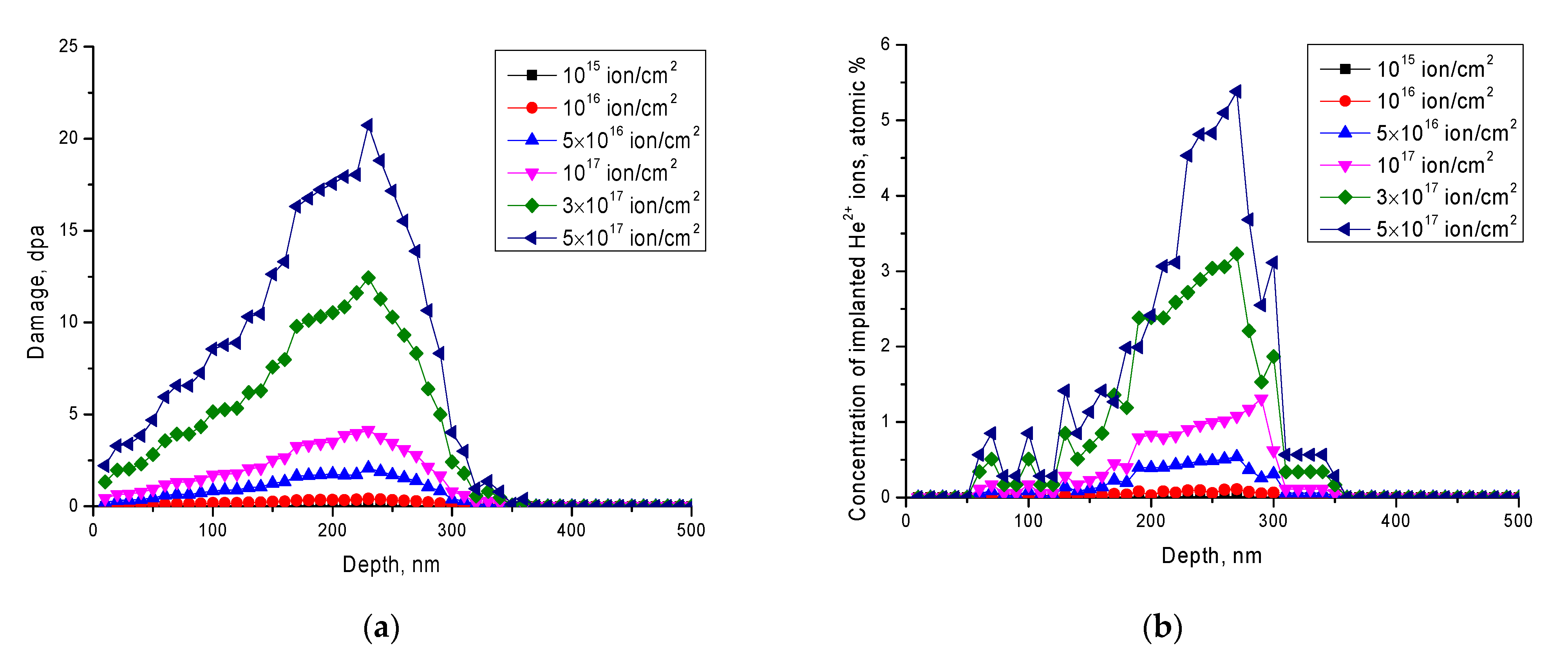
Figure 1 shows the results of analytical calculations of the values of atomic displacements (
dpa) and the concentration of He
2+ ions implanted into the structure of the near-surface layer, taking into account the distribution along the ion motion trajectory in the material. The calculations were performed on the basis of the obtained simulation data using the SRIM Pro 2013 program code and the methodology proposed by G.W. Egeland et al. [
42].
The value of displacements along the trajectory of ions in the material depending on the irradiation dose was carried out using the Formula (1) [
42]:
The implanted ion concentration depending on the radiation dose was determined by Formula (2) [
42]:
As can be seen from the data presented, the highest concentration of implanted ions, as well as the magnitude of atomic displacements, is observed at a depth of 180–270 nm, which corresponds to the maximum energy loss in this region. At the same time, the increase in displacements at a given depth with the achievement of a maximum can be explained by the fact that as a result of elastic and inelastic collisions of ions with atoms in the crystal lattice, and, accordingly, energy losses, the ion energy decreases, which leads to the fact that a larger contribution introduce losses during nuclear collisions, thereby forming additional displacements of atoms from the lattice sites. Additionally, in this area, a sharp increase in implanted helium ions is observed, which indicates that with the loss of energy, ions are able to penetrate into the nodes and interstices of the crystal structure, forming complex defects, thereby accumulating in the material. At the same time, it should be noted that an increase in the irradiation dose above 1017 ions/cm2 leads to a sharp increase in both the value of atomic displacements and the concentration of implanted ions in the damaged layer. As it is known from the literature data, the most pronounced process of helium swelling and formation of helium bubbles is observed at fluences of 1017–5 × 10¹⁷ ion/cm2, which is also associated with the concentration of implanted ions, which in some cases exceeds 1–3 at. %, and value of the shifts is more than 10 dpa.
Determination of the kinetics of structural changes as a result of radiation damage depending on irradiation fluence was carried out on the basis of X-ray diffraction analysis data. A series of X-ray diffraction patterns was obtained on a D8 Advance ECO X-ray diffractometer (Bruker GmbH, Mannheim, Germany). A copper tube with a wavelength of 1.54 Å was used as an X-ray source; X-ray diffraction patterns were taken in the Bragg-Brentano geometry in the angular range 2θ = 30–75°, with a step of 0.03°.
The determination of mechanical properties, in particular, hardness and degree of softening was carried out using the indentation method. For measurements, a LECO LM700 microhardness tester (Leco Corporation, St. Joseph, MI, USA) was used. A Vickers diamond pyramid was used as an indenter, the load on the indenter was 200 N.
The degree of softening (
DS) or reduction in resistance to deformation was determined based on changes in the hardness data of the near-surface layer before and after irradiation. Formula (3) was used for calculations [
40]:
where
H0 is the value of the hardness of the near-surface layer before irradiation,
Hirr is the hardness value of the near-surface layer after irradiation.
Normalization of the softening degree was carried out at 100%, the measurement error was calculated on the basis of a series of measurements of the hardness value from different areas.
Determination of strength properties, in particular, resistance to cracking as a result of long-term low-temperature degradation of the surface microstructure, was carried out by simulating tests of natural aging, under conditions of accelerated degradation, obtained by simulating external effects of water vapor at a temperature of 150 °C and a pressure of 2.2–2.3 atm. The crack resistance value (
Kc) was determined using Formula (4):
where
E is the Young’s modulus,
H is the Vickers hardness,
c is the length of the radial crack starting from the indenter indentation angle (pyramid),
a is the pyramid diagonal.
Impact strength and three-point bending tests were carried out to assess the reliability and performance of the materials under dynamic loading conditions and their tendency to brittle fracture resulting from deformation defects during irradiation and accumulation of radiation damage. The test was carried out on a special pendulum impact tester, according to ASTM D 7264/D7264M-07. The calculation of impact strength (
a) was carried out using Formula (5):
where ∆
WF is the amount of work expended by the pendulum on the destruction of the sample,
A is the cross-sectional area at the fracture site.
The study of morphological features and changes in the surface topography depending on the irradiation fluence was carried out using the methods of atomic force microscopy (AIST-NT SPM, Moscow, Russia) and scanning electron microscopy (Hitachi TM3030, Chiyoda City, Japan). The distribution of the elemental composition near the damaged areas was determined using the mapping method implemented using a Bruker XFlash MIN SVE attachment built into a scanning electron microscope.
3. Results and Discussion
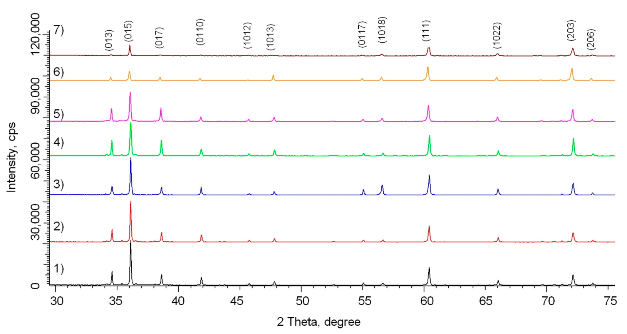
Figure 2 shows X-ray diffraction patterns of the studied SiC ceramic samples depending on the irradiation fluence. A full-profile analysis of the obtained diffraction patterns made it possible to establish that the samples under study have a hexagonal type of crystal lattice, which is characteristic of the P3m1(156) spatial syngony.
The general view of changes in diffraction patterns depending on irradiation fluence is characterized by changes in the intensity of reflections, as well as their shift to the region of small angles, which is characteristic of the deformation of the crystal structure. At the same time, the absence of the appearance of new reflections indicates the absence of polymorphic transformations in the structure. The absence of polymorphic transformations caused by irradiation indicates a high resistance to structural transformation processes; however, the observed structural changes are associated with the accumulation of point defects, their evolution, as well as helium implantation and its agglomeration into bubbles at high doses of irradiation.
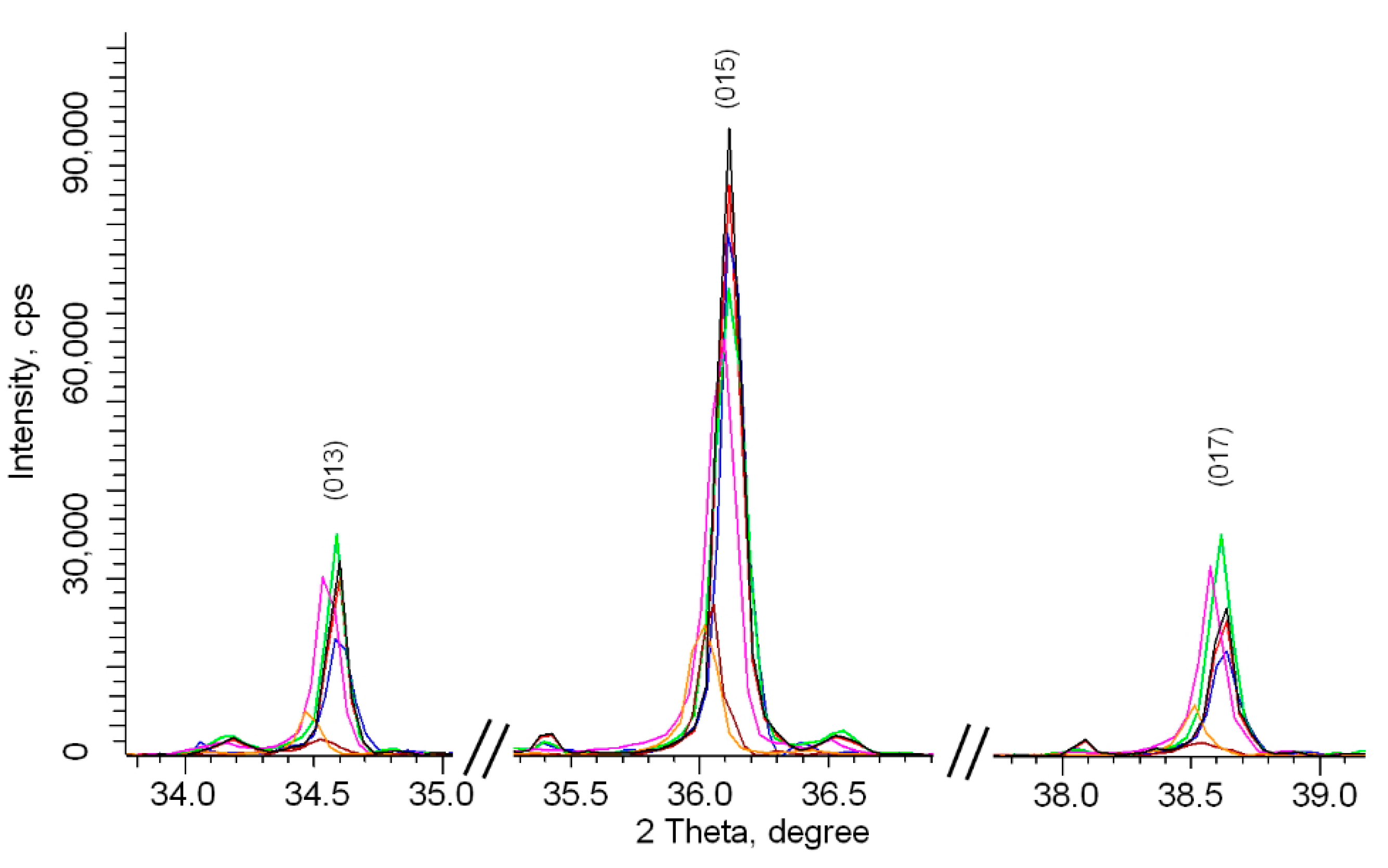
Figure 3 shows a detailed image of changes in the main diffraction reflections in the range of 2θ = 33–45°, which most fully reflect the structural changes depending on the irradiation fluence. As can be seen from the data presented, the main changes occur in three stages, characterized by different effects.
The first stage is characterized by changes associated with the broadening of lines and a decrease in the intensity of reflections, which is typical for structural changes associated with a change in the size of coherent scattering regions (crystallites). This stage is typical for irradiation fluences of 1015–5 × 10¹⁶ ion/cm2.
The second stage is typical for irradiation fluences of 5 × 10
16–10
17 ions/cm
2 and is associated with both a change in the intensity of the reflections and a shift of the reflections to the region of small angles. At the same time, the analysis of the shift value for various peaks showed that the reflections characteristic of the change in the crystal lattice parameter
а are shifted by a larger value than the reflection characteristic of changes in the crystal lattice parameter
c. Such a change in the value of reflection shifts indicates an anisotropic nature of the deformation of the crystal lattice. This character of anisotropy is due to the difference in the binding energies of the Si and C atoms, as well as the positions occupied by the atoms in the lattice sites [
43,
44].
The third stage is characterized by a strong asymmetry of diffraction reflections and their shift to the region of small angles, which indicates an increase in the deformation of the crystal structure as a result of the accumulation of radiation damage and helium implantation [
45].
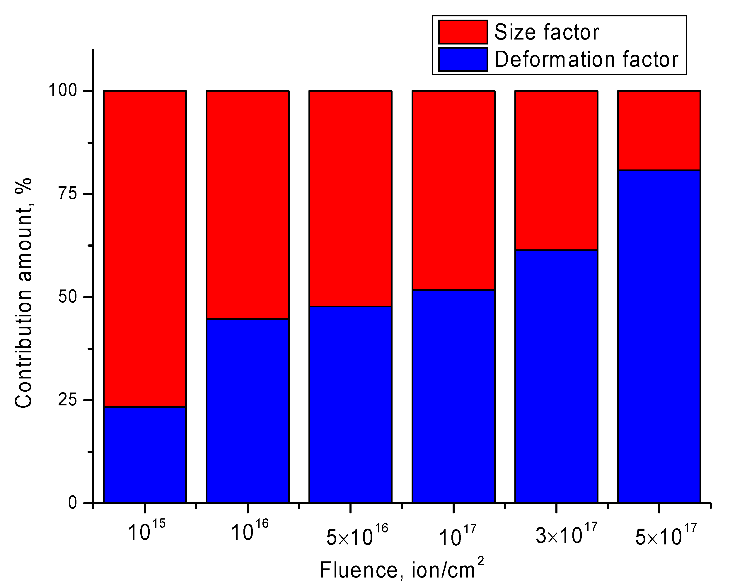
One of the ways to evaluate various factors affecting the change in diffraction reflections in terms of their broadening and displacement is the Williamson–Hall method, based on measuring the contributions of the size factor associated with a change in the size of crystallites as a result of external influences, and the deformation contribution associated with crystal lattice distortions. The following expression is used for the evaluation (6) [
46]:
where
β is the physical broadening of the diffraction maximum,
k = 0,9 is the dimensionless particle shape coefficient,
λ is the wavelength of the radiation used,
L is the size of the coherent scattering regions,
θ—Bragg angle,
ε is the value of crystal lattice microdistortions. The contribution assessment results are presented in
Figure 4.
The general view of the diagram shown in
Figure 3 confirms what was said above about the three-stage nature of the change in the structure during irradiation with He
2+ ions depending on irradiation fluence. At low irradiation fluences, the main contribution is made by the size factor, which, as mentioned above, is caused by recrystallization processes and changes in grain sizes. Such changes are associated with thermal effects that arise when the energy of incident ions is transferred to the material and the subsequent transformation of kinetic energy into thermal energy over very short time intervals. At the same time, in the case of low fluences, distortions and deformations of the crystal lattice also accumulate; however, this contribution is less noticeable in comparison with the size contribution. At high irradiation fluences, when helium bubbles begin to form in the structure, the deformation contribution dominates. At the same time, the formed helium bubbles exert a strong deformation distortion on the crystal structure, which leads to its swelling and deformation of the crystal lattice volume.
The change in the size factor as a result of external influences is due to the processes of crushing, reorientation of crystallites in the structure of the damaged layer, and also due to the transferred energy from incident ions.
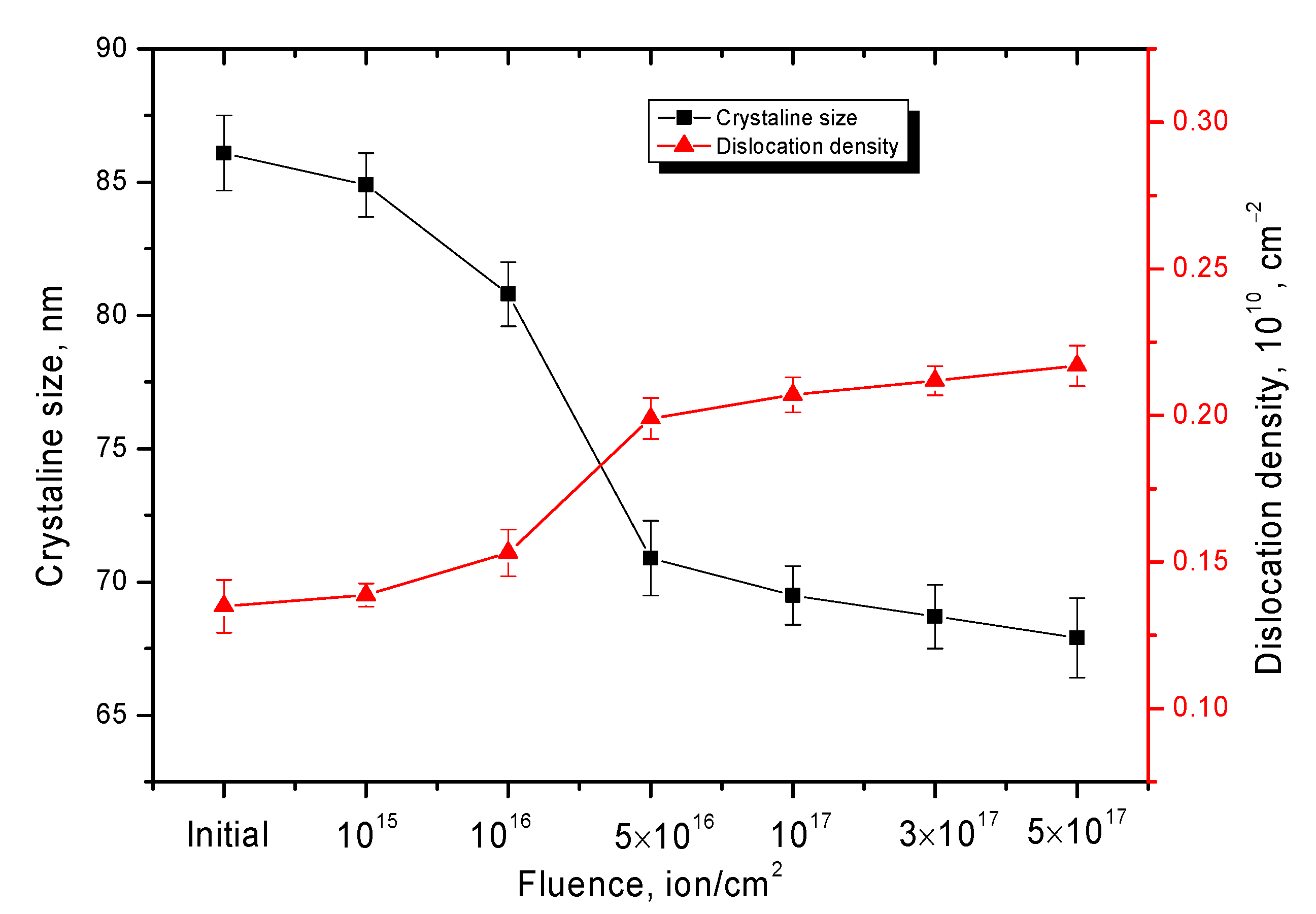
Figure 5 shows the results of the change in the size of crystallites, determined from the analysis of the obtained X-ray diffraction patterns, taking into account the contribution from distortions to the broadening of diffraction reflections, as well as the value of the dislocation density (
δ), determined using Formula (7) [
46].
where
L is the crystallite size.
As can be seen from the data presented, the changes in the size of crystallites depending on irradiation fluence are of a two-stage nature, which has a pronounced trend. The first stage is characterized by a sharp change in the size of crystallites in the direction of their reduction, which is due to the effect of grain crushing or their reorientation in the structure. At the same time, in the structure of the damaged layer, an increase in the dislocation density is observed, the value of which has an inverse quadratic dependence on the size of the crystallites, which means that in the case of a decrease in the size of the crystallites, the dislocation density will increase.
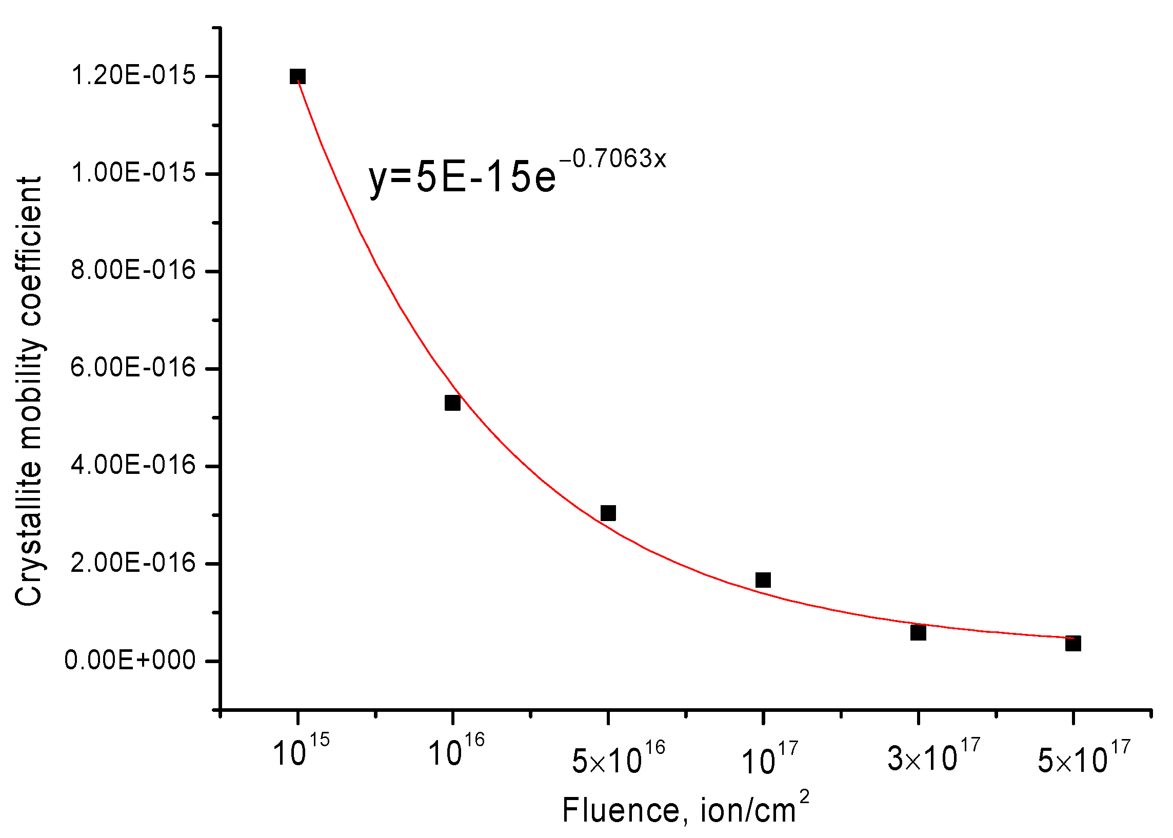
The second stage is typical for irradiation fluences above 10
17 ion/cm
2 and is characterized by small changes in the sizes of crystallites and dislocation density. This behavior of the quantities can be due to the effect of grain mobility deceleration as a result of an increase in the dislocation density, which acts as a limiting factor for recrystallization processes. Using Formula (8), which reflects the mobility coefficient of crystallites as a result of radiation-induced processes leading to their changes, a power-law dependence of the decrease in the mobility coefficient depending on the irradiation fluence was obtained.
where
φt is the ion fluence (flux multiplied by irradiation time),
k is the coefficient depending on the mobility of crystallites,
L and
L0 are the final and initial grain sizes. The results are presented in
Figure 6.
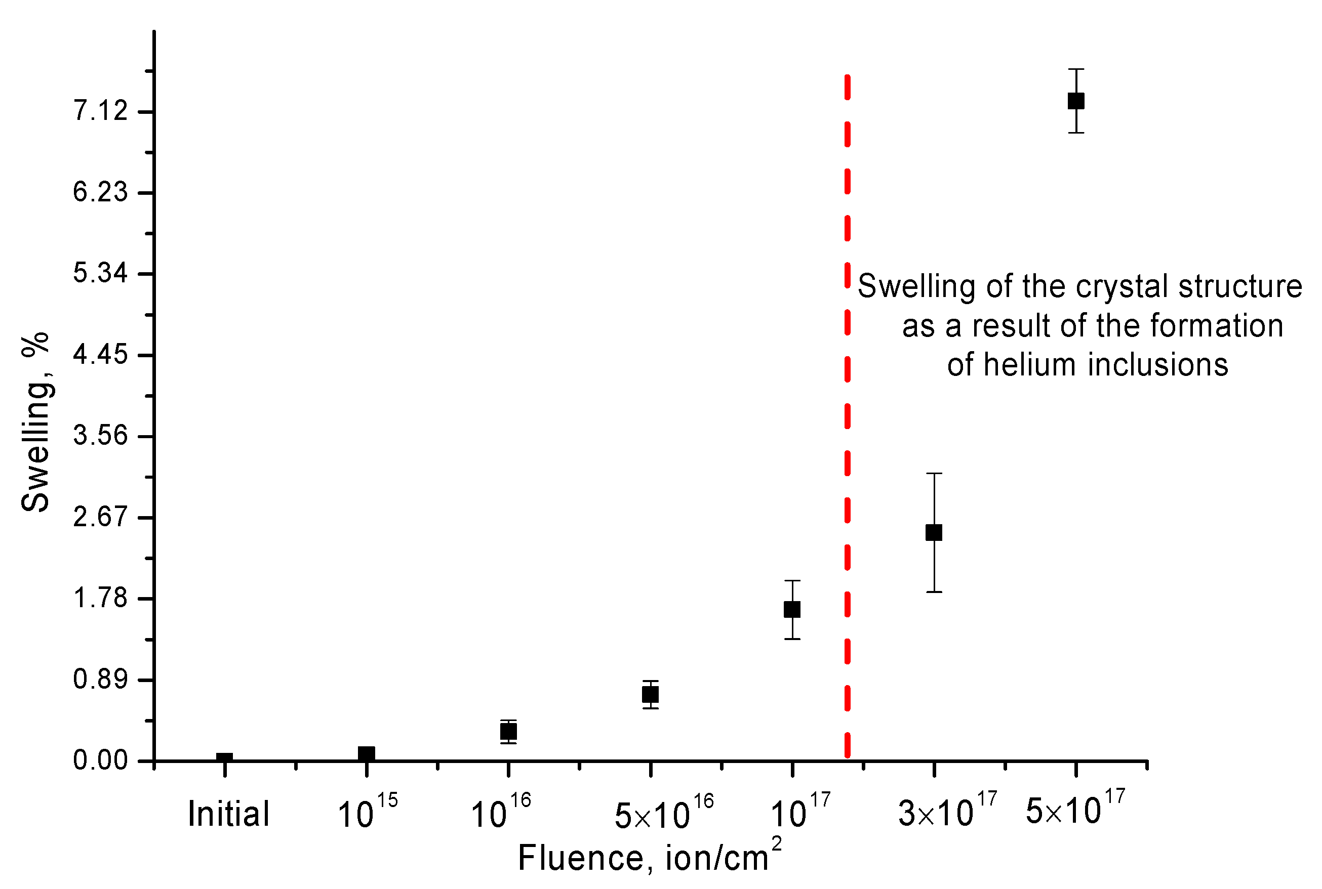
Figure 7 shows the results of changing the volume of the crystal lattice depending on the irradiation fluence. The change in the crystal lattice volume is associated with the accumulation of radiation damage and structural distortions caused by the transfer of the energy of incident ions to the crystal subsystem and its subsequent transformation into thermal energy.
The change in the crystal lattice volume was estimated using Formula (9):
where
V0 is the crystal lattice volume of the sample in the initial state (Å
3),
Virr is the crystal lattice volume of the sample after irradiation (Å
3). The crystal lattice was determined in comparison with card data from the database.
The general trend of changes in the processes of degradation of the crystal lattice indicates a high degree of resistance to swelling processes at radiation doses of 1015–1017 ions/cm2. At these doses, the maximum swelling degree is no more than 1.8%. At radiation doses above 1017 ion/cm2, for which, according to the calculated data of SRIM Pro 2013, the characteristic concentrations of implanted He2+ ions are more than 3–5 at. %, there is a sharp increase in the crystal lattice swelling degree, which is more than 2.5% for a dose of 3 × 10¹⁷ ion/cm2 and more than 7% for a dose of 5 × 10¹⁷ ion/cm2. Such an exponential increase in the swelling degree is due to the formation of helium bubbles in the structure of ceramics, which accumulate in the damaged layer of ceramics and cause additional distortions and deformations of the structure.
According to the Evans model, the main mechanism of helium swelling is the capture of helium by vacancy defects with the subsequent formation of He-V-type complexes, as well as the appearance of tensile stresses in regions filled with helium and He-V complexes. As a result, additional distortions appear in the structure, leading to deformation of the crystal lattice, as well as an increase in its size. At the same time, the main deformation effects are observed when the concentration of implanted helium exceeds 1–2 at. % or the value of atomic displacements is more than 5–10 dpa. In this case, agglomeration of microbubbles of implanted helium occurs, followed by the formation of sufficiently large inclusions, which lead to the appearance of microcracks in the structure [
47,
48].
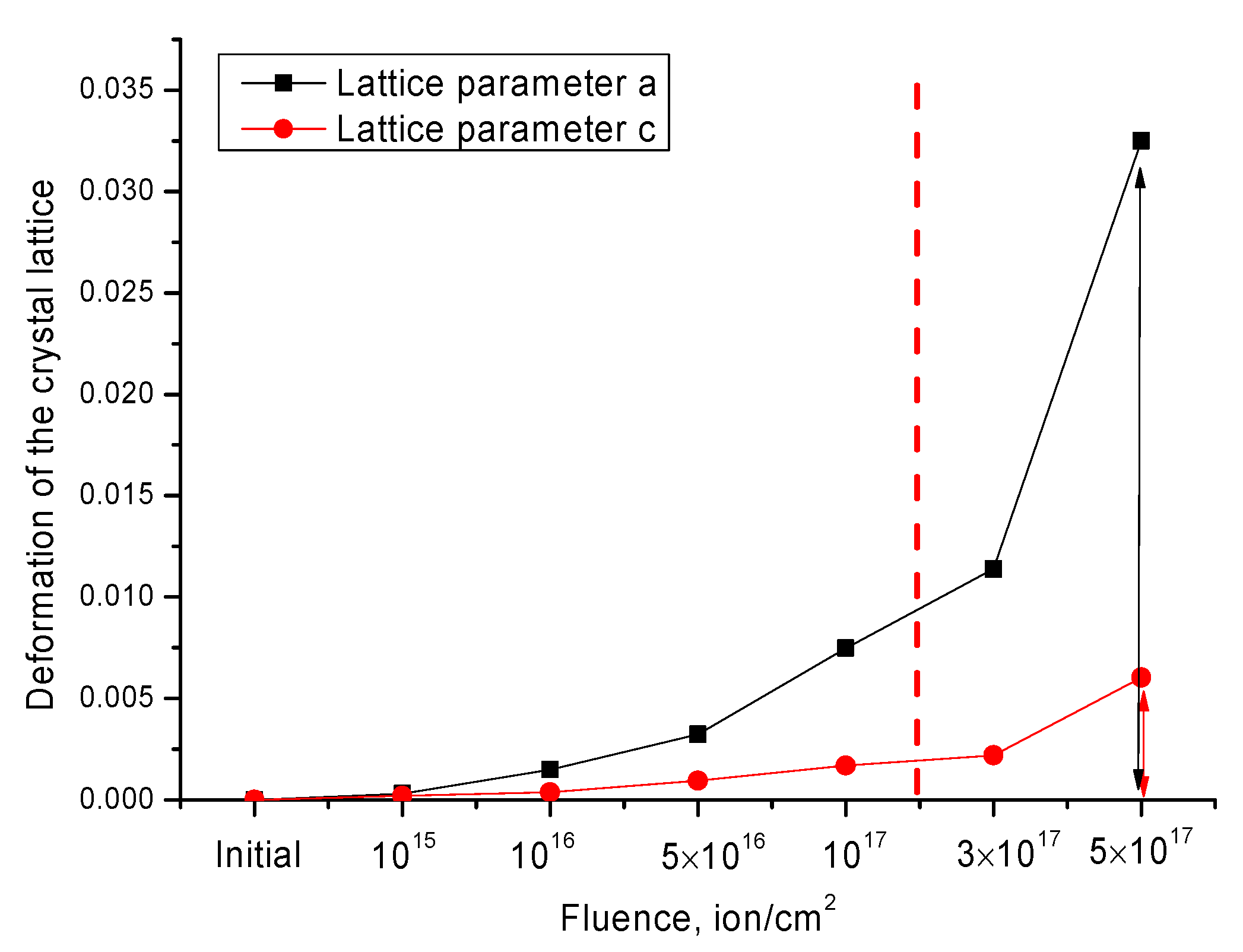
Table 2 shows the results of changes in lattice parameters depending on the irradiation dose.
As can be seen from the presented data, the greatest changes occur at fluences above 10
17 ion/cm
2, while according to the data shown in
Figure 8, the largest deformation of the crystal lattice is observed along the a axis at high irradiation fluences, which in turn indicates the anisotropic nature of the deformation of the crystal lattice as a result of irradiation.
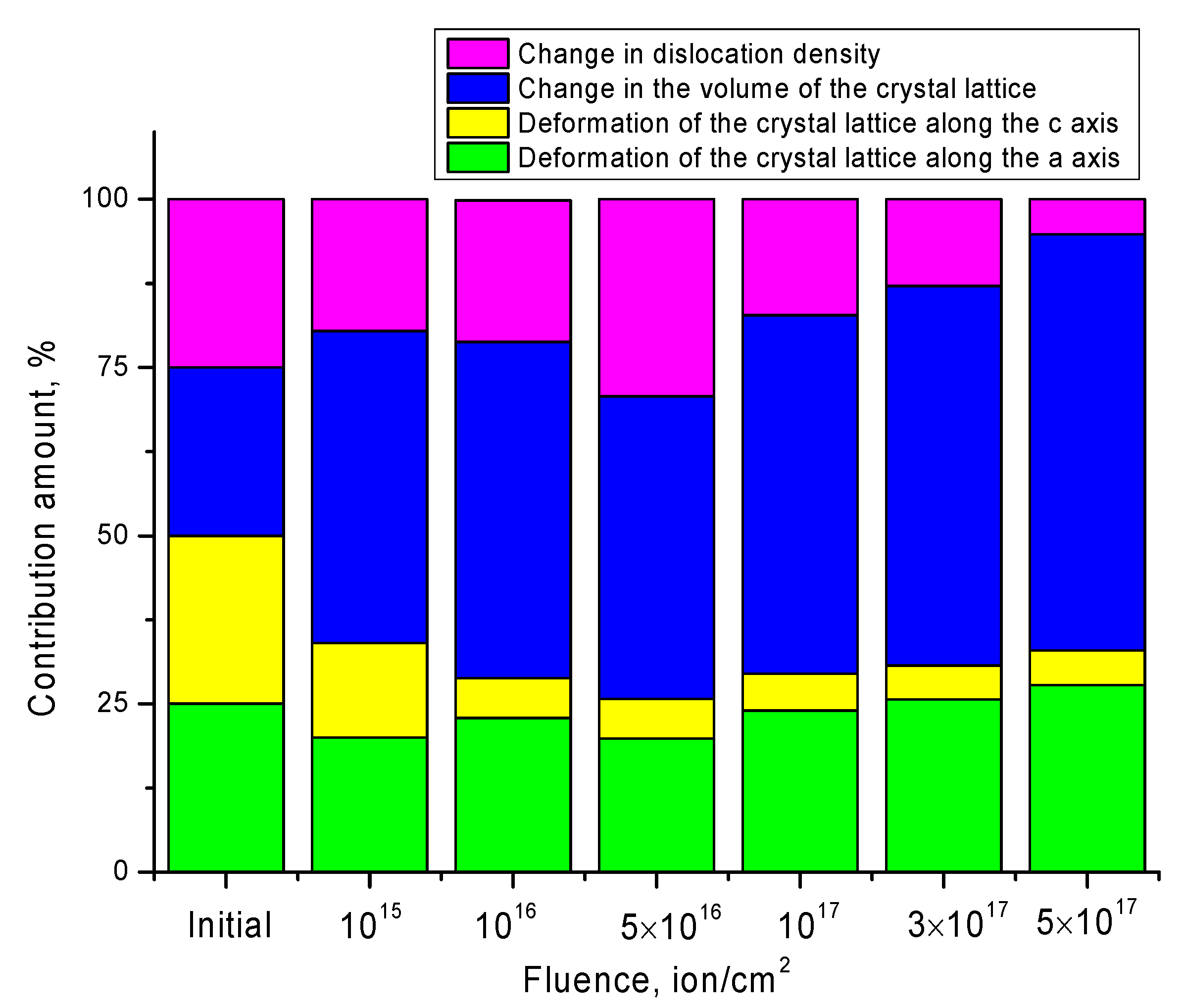
If we assume that the value of crystal structure radiation damage (
RD) is due to the deformation contributions of changes in the crystal lattice, changes in the volumes of the crystal lattice as a result of swelling, and dislocation density associated with a change in the size of crystallites, then the contributions can be estimated using the following Formula (10). Here, we need to introduce one condition that in the initial state the values of the contributions are equiprobable.
Δ
a is the deformation of the crystal lattice along the
a axis, Δ
c is the deformation of the crystal lattice along the
c axis, Δ
V is the change in the volume of the crystal lattice, Δ
δ is the change in the dislocation density.
Figure 9 shows a diagram of the assessment of contributions to the change in radiation damage value.
As can be seen from the data presented, at an irradiation fluence of 10
15 ion/cm
2, the main contribution to radiation damage is made by a change in the volume of the crystal lattice as a result of its swelling caused by the processes of ion implantation and the formation of vacancy defects. At the same time, the contributions from the deformation of the crystal lattice along the
a and
c axes, as well as changes in the dislocation density, are equally probable. This behavior of structural changes can be due to the effect of partial annihilation of the resulting point defects during irradiation. As it is known, at low concentrations of point defects, some of them are capable of annihilating with each other or with existing structural defects in the initial state. In this case, when the concentration of defects increases due to an increase in the irradiation fluence and the resulting structural damage to ions, as well as their implantation into the damaged layer, the effect of defect accumulation and their agglomeration dominate in the structure, which leads to an increase in crystal lattice distortions [
47].
At an irradiation fluence of 10
16–5×10
16 ion/cm
2, an increase in the contribution from the dislocation density is observed, which is due to a change in the size of crystallites as a result of irradiation. Additionally, at these fluences, the formation of an anisotropy of the deformation of the crystal lattice is observed, due to an increase in lattice distortions along the
a axis. At the same time, the contribution from the effect of swelling of the crystal lattice at these irradiation fluences remains practically unchanged, which indicates small changes in the lattice volume in this case depending on the irradiation fluence. A small change in the magnitude of swelling under irradiation fluences can be due to the onset of the nucleation of helium bubbles, which are formed due to the capture of helium by vacancies, followed by the formation of complexes of the He-V type and the filling of their cavities in the structure. In this case, the main role is played by deformations that occur during the formation of He-V complexes [
47,
48], as well as size effects caused by changes in crystallites, their mobility, or reorientation.
With an irradiation fluence of 10
17–5 × 10
17 ion/cm
2, a decrease in the contribution of dislocation density is observed, with an increase in anisotropy in the deformation of the crystal lattice, as well as the dominance of the contribution from swelling of the crystal lattice. The decrease in the contribution from the dislocation density may be due to the fact that, at fluences above 10
17 ion/cm
2, the concentration of implanted helium exceeds 1–2 at. %, which leads to the formation of helium bubbles as a result of agglomeration of He-V complexes. At the same time, according to the assessment of deformation and size factors affecting the change in the crystal structure, according to the Williamson–Hall method [
46], shown in
Figure 4, as well as changes in the size of crystallites at high irradiation fluences, the main contribution is made by deformation changes in the structure, while dimensional changes are minimal. Small changes in the size contribution can be due to the effect of reducing the mobility of grains due to their crushing and the formation of a large number of dislocation defects. The main contribution to the change in the value of radiation damage for these fluences is made by the effects associated with the swelling of the crystal lattice, which are due to the effect of helium agglomeration and the formation of helium bubbles. As it is known from the literature data, the formation of large helium bubbles in the structure of the near-surface layer, for most steels and ceramics, is observed when the threshold value of irradiation of 3–5 × 10
17 ion/cm
2 is reached, which corresponds to an implanted helium concentration of up to 3–5 at. %, and in some cases even more.
Moreover, at high irradiation fluences, a partial opening of the bubbles is possible, accompanied by cracking and peeling of the damaged near-surface layer. In this case, according to the work of Evans [
47,
48], a part of helium is able to migrate along dislocation defects, which also leads to a decrease in their density.
Thus, we can conclude that the proposed model for assessing the contributions of various structural changes to the radiation damage degree has several stages associated with different damage mechanisms. At irradiation fluences of 1015–5 × 10¹⁶ ion/cm2, the main contribution to radiation damage is made by changes in the dislocation density and anisotropic deformations of the crystal lattice. At irradiation fluences above 1017 ion/cm2, the dominant effect is the swelling of the crystal lattice and a change in its volume as a result of the accumulation of implanted helium in the structure of the damaged layer.
Let us consider irradiation effect on changes in the strength and mechanical properties of SiC ceramics depending on the irradiation fluence.
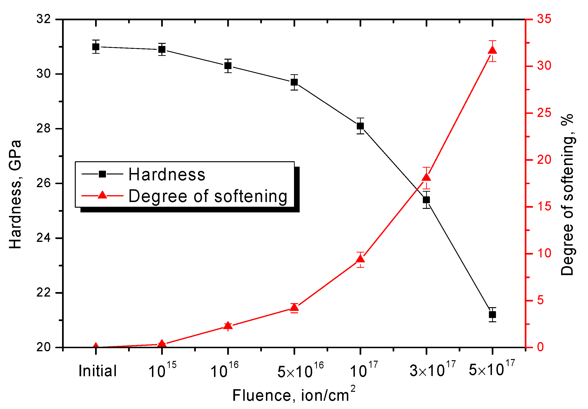
Figure 10 shows the results of measuring the hardness and degree of softening of the near-surface irradiated layer depending on the irradiation fluence.
As can be seen from the data presented, the most pronounced changes in the strength characteristics are observed at fluences above 5 × 10¹⁶ ion/cm2, which corresponds to the dominance of the crystal lattice swelling effect in structural changes. In the case when structural changes are associated with a change in the dislocation density, changes in the hardness and degree of softening of the near-surface layer are minimal. The maximum decrease in strength properties occurs at irradiation fluences of 3 × 10¹⁷–5 × 10¹⁷ ions/cm2, when structural changes are caused by degradation processes and swelling caused by the accumulation of helium inclusions with an increase in the concentration of implanted ions. It should be noted that an increase in the degree of softening above 15–20% indicates the destruction of the surface layer, which is caused by embrittlement processes, as well as the formation of microcracks.
Table 3 presents the results of the measurements of the parameters of bending strength and impact strength of SiC ceramics depending on the irradiation fluence. The dependences obtained reflect a similar dynamic of changes as in the case of hardness, which indicates that the change in strength characteristics is greatly influenced by the effect of agglomeration and accumulation of helium in the damaged layer at high doses of radiation.
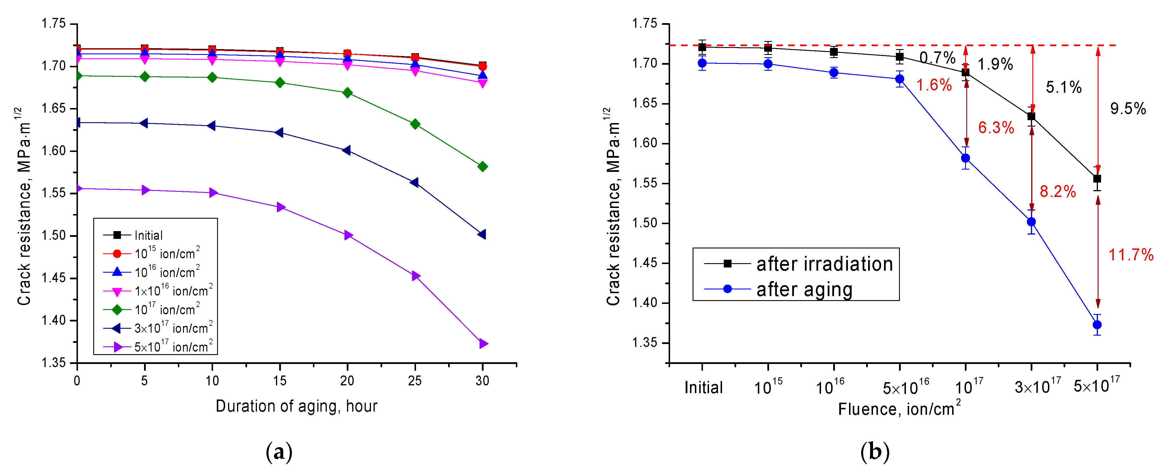
Figure 11 shows the results of changes in the crack resistance value depending on the irradiation fluence, as well as the results of simulation of the effect of surface layer natural degradation as a result of external influences.
The general trend of changes in the crack resistance depending on the irradiation fluence indicates that the main deterioration associated with the formation of microcracks in the structure of the irradiated layer occurs when samples are irradiated with fluences above 1017 ion/cm2, for which the main changes in the structure are associated with the accumulation of radiation damage, an increase in the concentration of implanted ions, as well as a strong anisotropy of structural distortions of the crystal lattice, which together leads to the formation of disorder regions in the structure, as well as helium inclusions.
At the same time, it should be noted that in the case when the effects associated with a change in the dislocation density play an important role in structural changes, changes in the crack resistance, especially during long-term tests, are practically not observed. This may be due to the fact that a change in the dislocation density in the damaged layer leads to the creation of resistance to the propagation of microcracks resulting from external influences.
The results of degradation measurements of a decrease in the crack resistance coefficient during the time intervals of exposure to water vapor, simulating the effect of accelerated natural aging, indicate a fairly high degree of resistance to natural cracking as a result of external influences, both in the case of initial samples and those subjected to irradiation.
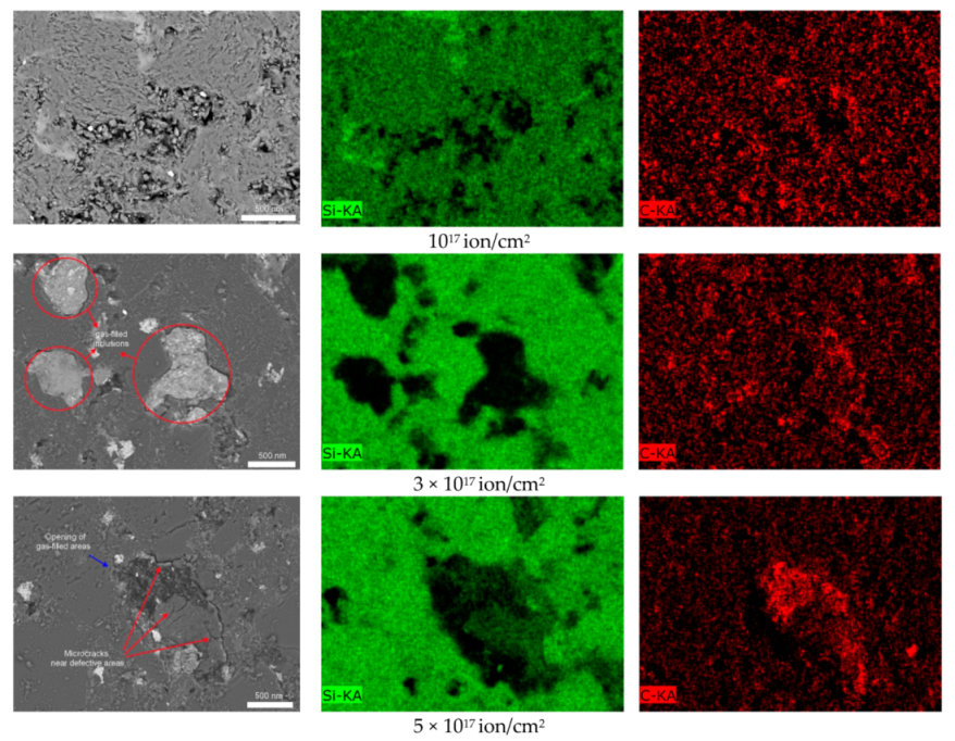
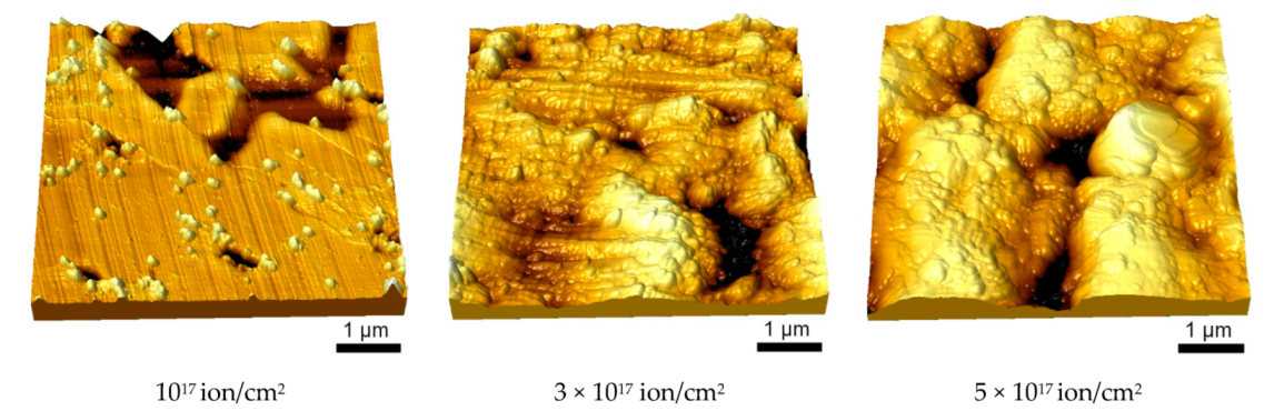
The results of studying the change in morphological features of SiC ceramics depending on irradiation fluence are shown in
Figure 12. In the initial state, the surface of the ceramics looks quite even, without obvious visible damage or cracks, and the presence of roughness is due to the processes of polishing and sample preparation of the samples. The general trend of changes in the morphology and relief of the surface is expressed in a change in roughness and the appearance of defective inclusions that arise with an increase in irradiation fluence, the further evolution of which leads to an increase in their density and shape. This behavior is due to the formation of additional distortions and stresses in the structure of the near-surface layer, which can deform the crystal structure. As a result of helium implantation, which leads to swelling, these stresses lead to the deformation of the grains and their partial extrusion to the surface. It should be noted that the formation of defective regions can also be associated with the effect of partial chipping or sputtering at high radiation doses. Additionally, at high irradiation fluences, the formation of gas-filled inclusions squeezed onto the surface is observed, the final evolution of which at a fluence above 3 × 10
17 ion/cm
2 is the formation of chips and microcracks near the destroyed gas-filled regions.
During the analysis of the distribution of elements near defective regions for samples irradiated with fluences above 1017 ion/cm2, it was found that the defective regions themselves contain more carbon, while silicon in the defective regions was observed only in the form of trace inclusions. This behavior of the redistribution of elements near defective regions may be due to the fact that when the crystalline and chemical Si-C bonds are broken, carbon is inherently more mobile, and can also form complex defects together with vacancies or helium, followed by migration to regions filled with implanted helium.
In the case when the helium concentration in the filled voids reaches a critical value and leads to a sharp increase in pressure inside the area, which acts equally likely in all directions, causing stresses in the damaged area, the so-called “opening” of gas-filled bubbles and the formation of microcracks and chips occur (see
Figure 13 results for a sample irradiated with fluence of 5 × 10
17 ion/cm
2). At the same time, new gas-filled inclusions are formed near the formed microcracks, which represent the second generation of helium bubbles.
Figure 14 shows the evolution of the surface relief of SiC ceramics at high irradiation fluences (10
17–5 × 10
17 ion/cm
2), which reflects the nucleation of helium bubbles, their agglomeration, and the formation of microcracks.
The results of morphological features of SiC ceramics exposed to irradiation with He2+ ions are in good agreement with the results of structural changes depending on the irradiation fluence. At irradiation fluences of 1015–5 × 10¹⁶ ion/cm2, when structural changes are associated with recrystallization processes and changes in dislocation density, morphological changes in the relief are not pronounced, and are mainly associated with a slight change in roughness, as well as the formation of defective areas squeezed onto the surface. When the swelling effects due to the accumulation of implanted helium and the formation of helium bubbles begin to dominate in the structure, sharp changes in the relief are observed associated with the formation of single hillocks, followed by their agglomeration and the formation of microcracks.
The formation of microcracks and degradation of the surface at irradiation fluences above 1017 ion/cm2 also provide good confirmation of the change in mechanical and strength properties, the greatest changes that are observed at high irradiation fluences. Accumulation of damage and subsequent degradation of the surface by opening gas-filled bubbles leads to the destruction of the crystal structure, which in turn adversely affects the strength and resistance of ceramics to cracking.


 ,
, 

