This section describes the design of broadband stripline circulators. First, analytical methods are described to determine the ferrite parameters, resonator dimensions, and impedance matching conditions. Next, electromagnetic simulations based on the derived analytical equations are described to validate and optimize the designs. Finally, the fabrication of prototypes is described, following the simulations, in order to realize the proposed structures.
3.1. Analytical Methods
The design parameters were determined analytically based on an extensive review of the literature. The first step involved calculating the ferrite saturation magnetization (
), which directly influences the center frequency, bandwidth, and insertion loss. Several approaches for calculating
have been reported [
9,
13]; in this work, the appropriate range was obtained using Equation (
1).
Here,
f is the center frequency,
is the gyromagnetic ratio (2.8 MHz/Oe), and
denotes the anisotropy field varying within 0–100 Oe. For circulators operating in the below-resonance mode, the internal magnetic field is assumed to be
, meaning that the ferrite is not fully magnetically saturated [
3]. Under this condition, the relative permeability is approximated as
, and the effective magnetic permeability of the ferrite,
, can be expressed as:
where
and
represent the real and imaginary parts of the permeability tensor, respectively. The obtained
serves as a key parameter linking ferrite properties to resonant behavior and provides the basis for determining the radius of the ferrite disk, which is given by Equation (
3).
According to Equation (
3),
c is the speed of light,
and
are the permeability and permittivity of free space,
is the dielectric constant of the ferrite, and
is a shape-dependent constant obtained from the solution of the Bessel function. This relation indicates that the radius of the ferrite disk depends on both the intrinsic properties of the ferrite and the operating frequency. After determining
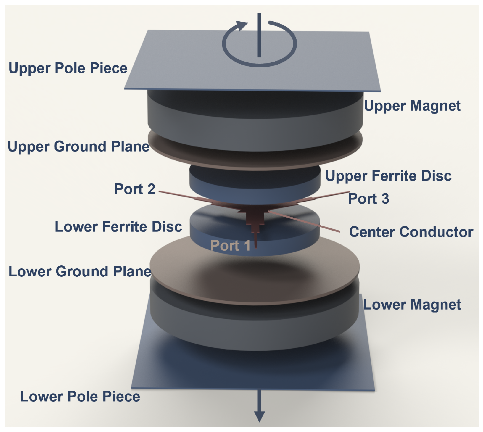
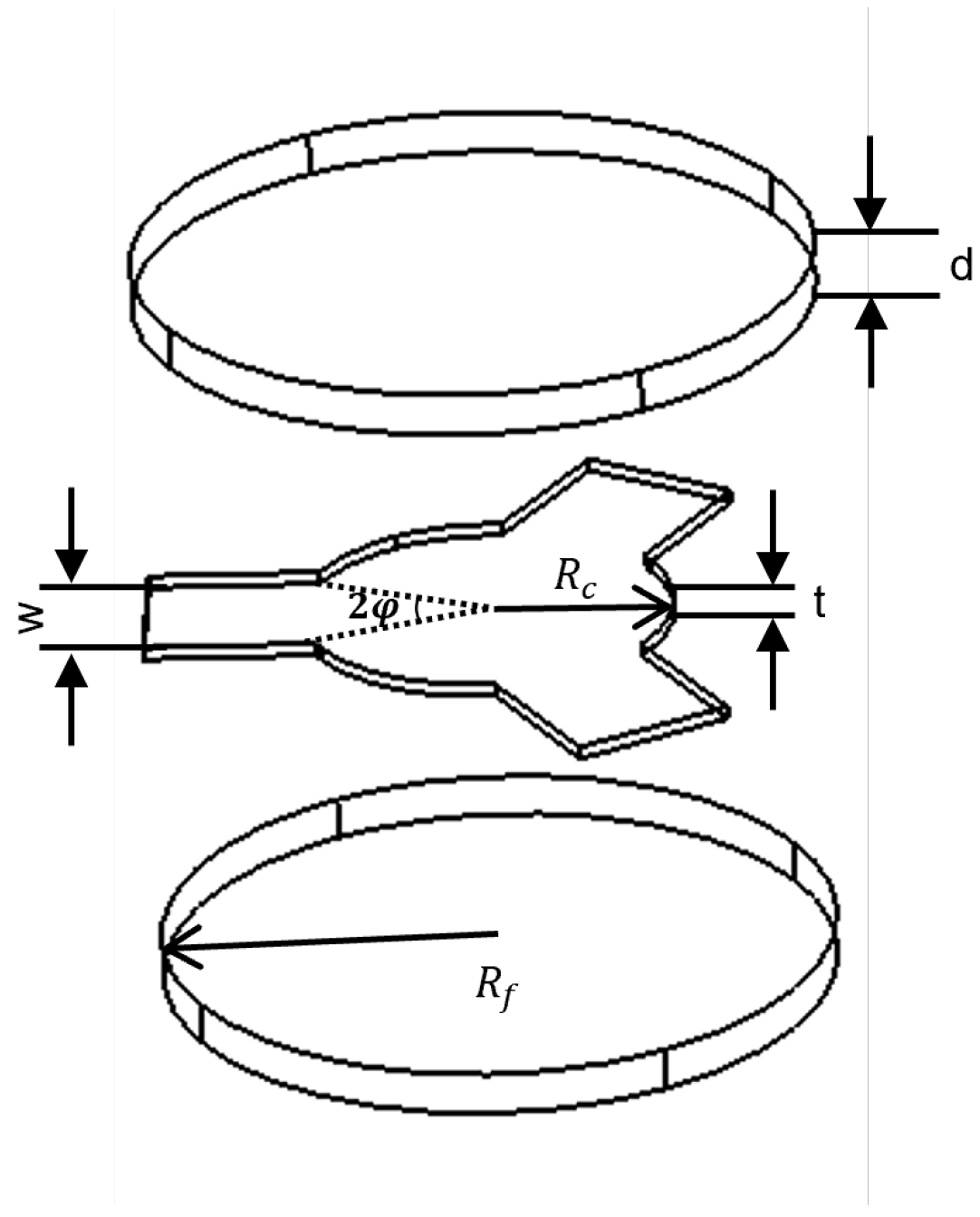
, the next step is to specify the center conductor geometry to achieve proper coupling within the Y-junction configuration, as illustrated in
Figure 2, which shows the geometry of a typical stripline circulator including the center conductor and the ferrite disk.
The geometry of the center conductor can be designed in triangular, hexagonal, or star forms. These variations strongly affect parameters such as the resonant frequency, the susceptance slope (
), and the conductance (
) of the center conductor, although having only a limited influence on the loaded quality factor (
) [
2]. The conductance of the circulator at the center frequency is expressed as a function of the wave admittance in Equation (
4) [
5]:
with
denoting coupling angle and
representing the mode-splitting ratio. The wave admittance (
), determined by the dielectric and magnetic properties of the ferrite, is given in Equation (
5).
In this expression,
,
, and
correspond to the vacuum permittivity, the relative dielectric constant, and the effective magnetic permeability, respectively. The loaded quality factor (
) characterizes the relation between the energy stored in the ferrite and the power transferred to the strip lines [
2,
5]. A low
provides a wider isolation bandwidth, while a high
reduces insertion loss and facilitates more efficient power transfer. This relation is defined as follows:
where
d is the thickness of the ferrite and
is the angular frequency. To estimate the insertion loss of a below-resonance circulator, Fay and Comstock [
5] defined the unloaded quality factor, which is given in Equation (
7).
In this formula,
denotes the dielectric loss tangent of the ferrite, and
corresponds to the linewidth. Using the calculated
, the insertion loss can be obtained from Equation (
8).
Thickness of the ferrite is a fundamental design parameter and is often approximated as
(free-space wavelength), as suggested by Simon [
15]. However, this value should not be regarded as a strict limitation for stripline circulators, since variations in thickness can be compensated by modifying either the center conductor geometry or the stripline width [
4]. For example, if a thinner ferrite is required in a disk-type resonator, switching to a corner-coupled triangular geometry can reduce the thickness to nearly one-third, whereas implementing a side-coupled triangular geometry can increase it by a factor of three. As expressed in Equation (
6), the ferrite thickness (
d) is inversely related to both the susceptance slope (
) and the resonator input conductance (
). As illustrated in
Figure 2, the width (
W) of the center conductor guiding the electromagnetic wave in the circulator is directly proportional to the coupling angle (
). In the Y-junction configuration, the three transmission lines are symmetrically connected to the center conductor at 120 ° intervals [
2]. The stripline width is defined in Equation (
9) as a function of the coupling angle and the center conductor radius
.
Smaller coupling angles are particularly advantageous for broadband operation. Wu and Rosenbaum [
6] demonstrated that reducing the coupling angle from
to
under weak coupling conditions increases the bandwidth. These findings are supported by analyses based on the continuous tracking technique and are consistent with the measurement results reported in [
7,
8,
15]. In addition, according to the study of Jaiswal and Pradeepkumar [
9], the center conductor diameter should be chosen to be approximately 80% of the resonator disk diameter for broadband applications. The bandwidth, for cases where the circulator junction impedance is not matched to the system characteristic impedance (typically
), was defined by Bosma [
4] in Equation (
10):
where
is the maximum voltage reflection coefficient within the band and is directly related to VSWR. As indicated by this relation, the bandwidth depends on the resonance frequency splitting caused by two counter-rotating modes formed within the ferrite resonator. The magnitude of this splitting is proportional to the gyromagnetic ratio
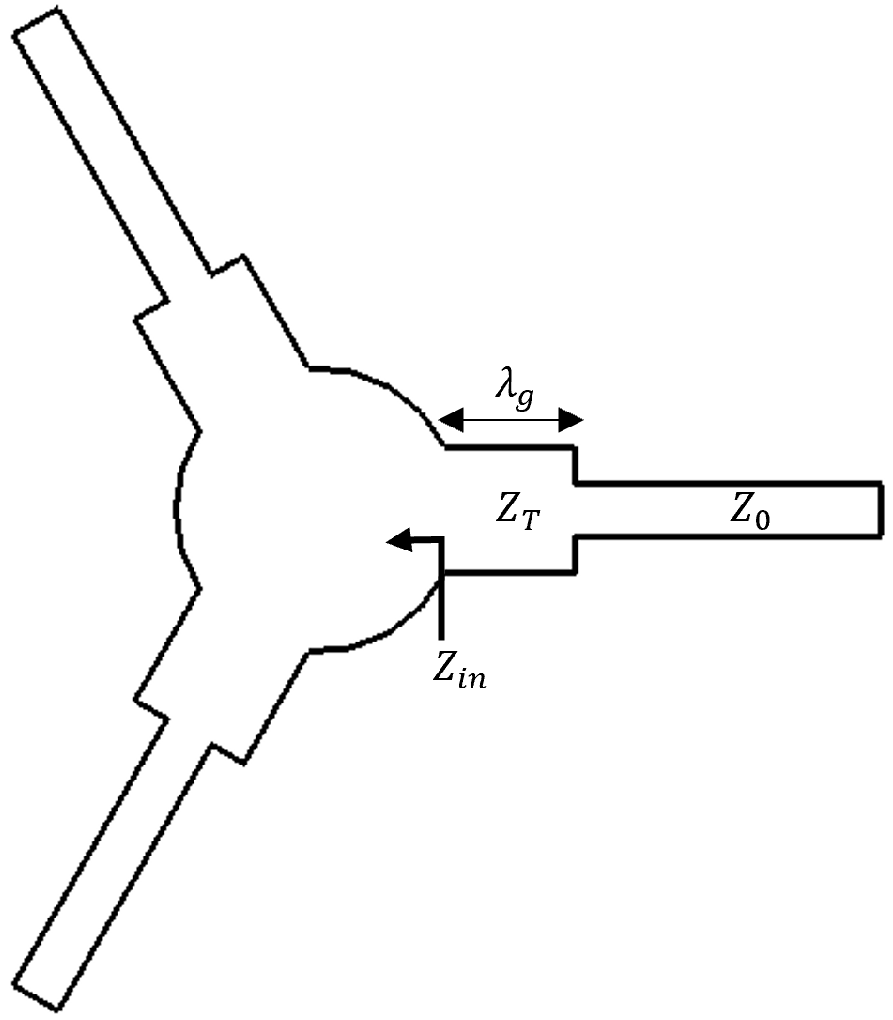
. In the absence of impedance matching, the achievable bandwidth remains limited. To overcome this limitation, quarter-wave impedance transformers are commonly employed to match the input impedance of the center conductor to the system impedance. These transformers convert the resonator impedance to the system characteristic impedance, thereby allowing broader bandwidths [
2,
9]. A single-stage transformer is illustrated in
Figure 3, and its transformation relation is given in Equation (
11).
Here, denotes the characteristic impedance of the transformer line, and is the input impedance to be matched. The electrical length of the transformer is chosen as at the design frequency, where is the guided wavelength.
In this context, single-stage transformed structures remain narrowband. For broadband applications, multi-stage or more complex transformer topologies (e.g., Chebyshev, Binomial) are preferred. A detailed analysis of these design methods is discussed by Pozar [
1]. For a circulator to operate, an external magnetic field must be applied to initiate the gyration of electrons in the ferrite. It is essential that this field remain homogeneous and uniformly distributed over the ferrite; otherwise, some regions may not be fully magnetized, leading to degraded performance and increased insertion loss [
3]. In below-resonance circulators, the internal magnetic field of a not-yet-saturated ferrite is commonly assumed to be zero. However, to avoid low-field losses, the applied field must be strong enough to drive the material into saturation. The optimum internal magnetic field
is defined in Equation (
12) as the combined effect of the externally applied field
, the anisotropy field
, and the demagnetization field
.
Here, the demagnetization field is defined as
, where
is the demagnetization factor determined by the ferrite geometry and the orientation of the applied field. Its value lies between 0 and 1, and for disk-shaped ferrite structures,
has been reported in the literature [
16]. The anisotropy field
accounts for the effect of randomly oriented magnetic dipoles within the ferrite and is typically chosen in the range of 0–100 Oe to represent these effects and compensate for experimental uncertainties.
3.2. Practical Method in Simulations
In this part of the study, the parameters calculated by analytical methods were validated and optimized through full-wave electromagnetic simulations performed with the Frequency Domain Solver of CST-MWS [
17]. The design process started by evaluating Equation (
1) at the center frequency and continued with the determination of the optimum saturation magnetization. The ranges obtained from this calculation are presented in
Table 2.
A ferrite material consistent with the properties in
Table 2 was investigated by surveying several manufacturers. During this process, parameters such as saturation magnetization, resonance linewidth, and dielectric constant were considered. Based on these evaluations, the aluminum-doped AL800 ferrite from TCI [
18] was selected for use in both prototypes due to its low-loss characteristics. The material properties are summarized in
Table 3.
The next step of the design was to select the dielectric material surrounding the ferrite, for which the guidelines reported in the literature were also considered. In accordance with the study by Elhanafy et al. [
19], the design frequency should be set approximately 5% higher than the center frequency, and the relative permittivity of the dielectric should be about 60% lower than that of the ferrite material. Accordingly, the K9 dielectric material from TCI [
18], with
and
, was implemented. In both designs, the dielectric thickness was set equal to the ferrite thickness to eliminate discontinuities caused by height differences and to simplify assembly. Based on these recommendations, the ferrite disk radius was calculated using Equations (
2) and (
3), and these values are summarized in
Table 4.
Following the determination of ferrite and dielectric properties, it is equally important to evaluate the geometric ratios that govern the resonant behavior of the structure. Linkhart [
3], as expressed in Equations (
13), defined the ratio of the radius of the air or insulating region surrounding the ferrite (
) to the ferrite radius (
) as a key parameter for keeping the resonant frequencies outside the operating band. He further indicated that, for disk-type ferrites, selecting the center conductor radius (
) within a specific range of ratios provides suitable performance for broadband operation.
The bandwidth performance of circulators is primarily determined by the impedance matching between the center conductor junction and the standard 50 Ω ports. This matching is generally obtained by using one- or two-section quarter-wavelength impedance transformers. As proved by Linkhart [
3], based on VSWR value between minimum and maximum specified in the operating band, the coupling impedance (
) should be in the range of 12.5–25 Ω. Variations in this parameter affect the loaded quality factor and ferrite thickness. In this study, the synthesis method described in [
3] was implemented to determine the network parameters, with the equations solved iteratively to ensure accuracy and efficiency. The resulting values for two prototypes operating in different frequency bands, derived using the specified VSWR constraints, are presented in
Table 5.
The thickness (
t) of the center conductor is a key geometric parameter in the design of the stripline circulator, directly influencing the distribution of the electromagnetic field, the characteristic impedance and the density of RF current. Variations in conductor thickness can significantly influence impedance values and therefore limit system performance [
1]. In this study, the thickness of the center conductor was fixed at 0.3 mm to ensure the desired impedance match and to simplify fabrication.
Based on these design choices, the analytically obtained parameters for the circulator designs are summarized in
Table 6. As standard products with ferrite radius and thickness values exactly matching the calculated results were not available on the market, custom fabrication was considered but not preferred due to the high costs and long lead times associated with overseas suppliers. Instead, another AL800-type ferrite (diameter: 15.9 mm, thickness: 2.54 mm), which provided the closest physical properties to the target values, was procured from TCI [
18]. For the dielectric layer, the electrical properties and geometric dimensions of the required K9 material [
18] were specified, and the material was produced by a local manufacturer, Solak Laboratory (Solak Lab., (Kupfer Advanced Materials Technologies, Istanbul, Turkey)) [
20]. In addition, to evaluate the performance of domestically produced ferrite materials, an AL800-type [
20] ferrite sample with the same dimensions was manufactured locally by Solak Laboratory.
The coupling impedance
calculated for prototype-1 in
Table 5 was only 4.6
, which is considerably lower than expected. To address this limitation, the disk-type center conductor was redesigned into a side-coupled triangular geometry, increasing the impedance to 13.85
—a nearly threefold improvement [
3]. Since the design aimed to cover a full octave bandwidth, three Chebyshev impedance transformers were employed instead of two, as this approach provides improved matching and wider bandwidth. The theoretical background and design methodology of this transformer topology are described in detail in [
1]. The updated analytical results are summarized in
Table 7. Using these parameters, circulators for both frequency bands were modeled in CST Microwave Studio, and frequency-domain simulations were carried out [
17].
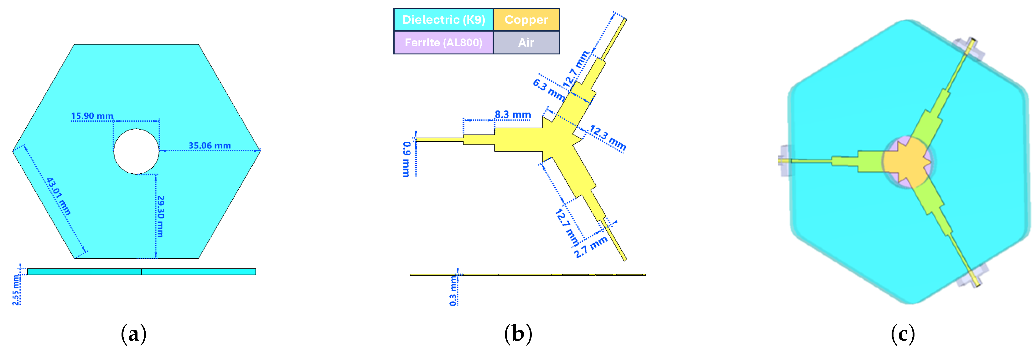
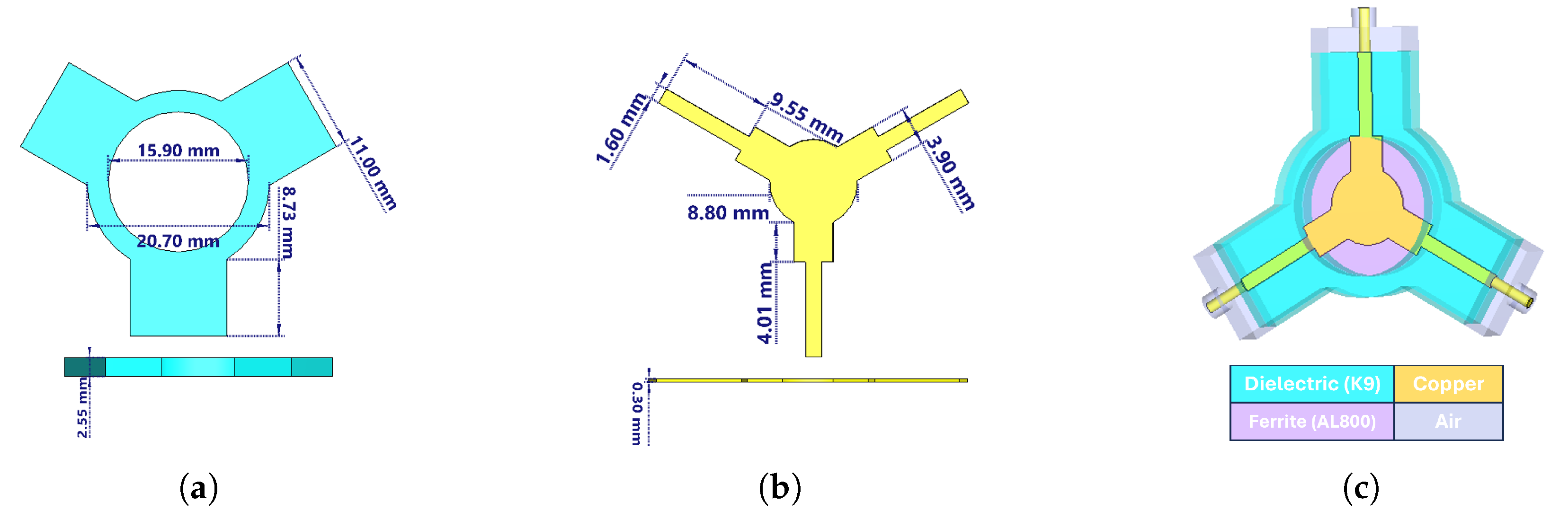
Figure 4 and
Figure 5 present the three-dimensional designs of the prototype-1 and prototype-2 circulators, respectively.
As seen in
Figure 4c and
Figure 5c, transition sections were designed between the coaxial line (SMA) and the stripline in both prototypes. While the coaxial line supports a pure TEM mode, the stripline operates in a quasi-TEM mode. Therefore, the transition was introduced to enable a smooth conversion from the coaxial TEM mode to the quasi-TEM stripline mode while also compensating for the reactive part of the impedance. The total transition length was set equal to the SMA connector pin length (5 mm), and the remaining dimensions were optimized to reach the desired performance. As summarized in
Table 7, the lengths of the quarter-wave transformers were slightly extended to achieve proper impedance transformation. The S-parameter results obtained after these optimizations are shown in
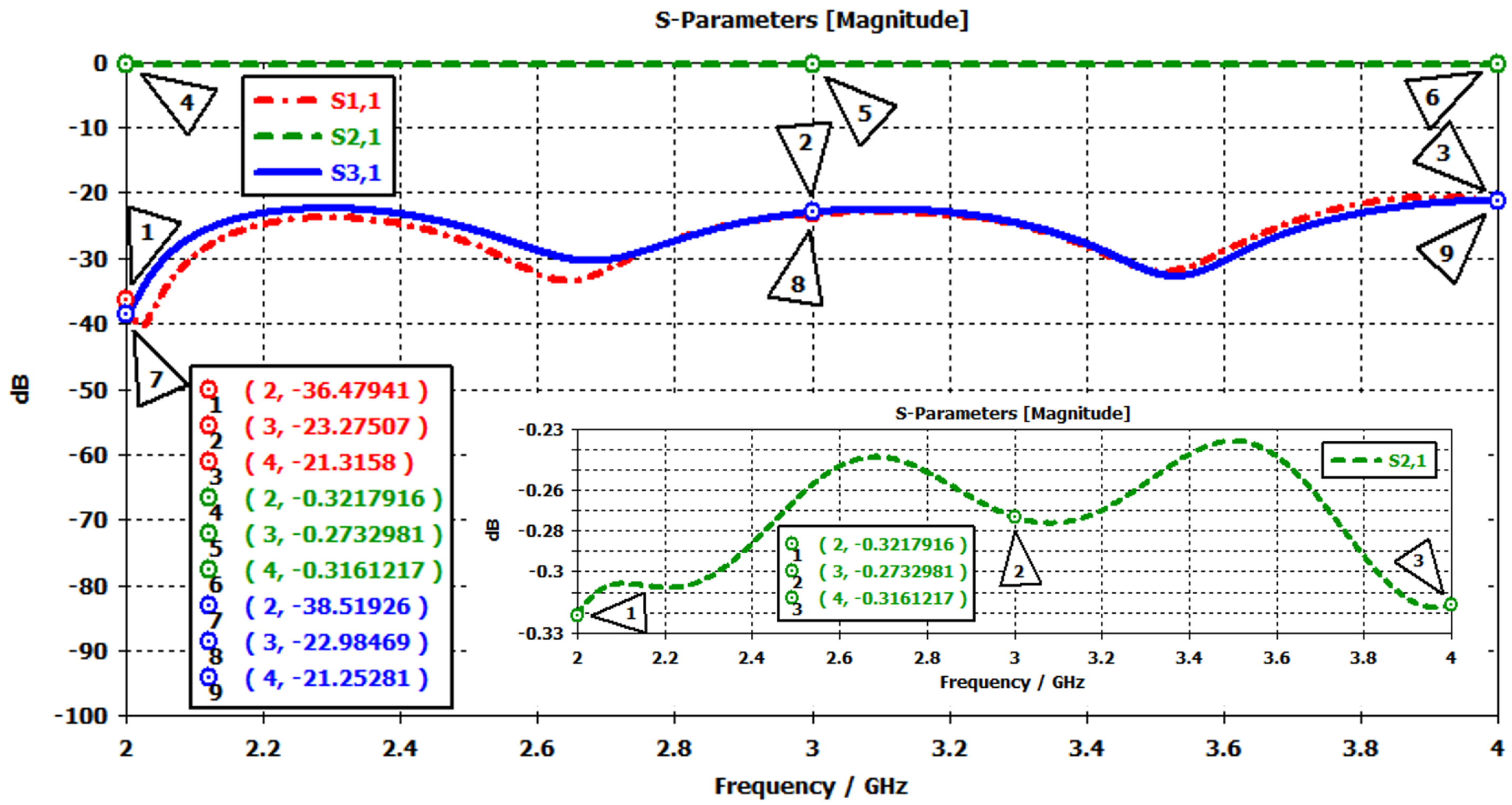
Figure 6 and
Figure 7.
Prototype-1 was simulated using the parameter values listed in
Table 7. The corresponding results are shown in
Figure 6. The targeted frequency range is clearly covered, as indicated by the
trace (red curve), which remains between −21 and −36 dB, confirming good input matching. The insertion loss (
, green curve) is approximately −0.3 dB across the band, demonstrating low-loss performance. The isolation (
, blue curve) varies between −21 and −38 dB. These results confirm that prototype-1 achieves broadband operation with low insertion loss, strong input matching, and acceptable isolation levels across the band.
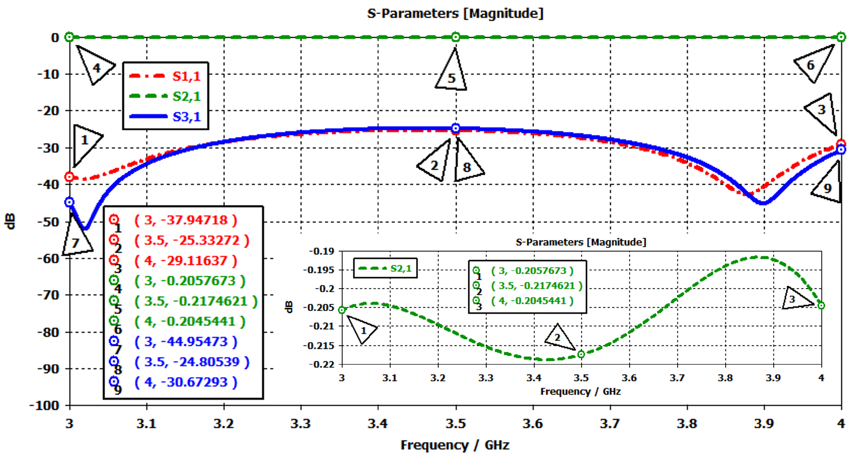
With a similar approach, one can observe that the other prototype also provides the desired results, as declared in
Table 1. The corresponding S-parameter results are shown in
Figure 7. The
trace (red curve) remains well below −20 dB across the entire band, with values of −38 dB at 3 GHz, −25 dB at 3.5 GHz, and −29 dB at 4 GHz, indicating good input matching. The insertion loss (
, green curve) is nearly constant at around −0.2 dB, confirming efficient low-loss transmission. The isolation characteristic (
, blue curve) varies between −25 and −45 dB, reaching a maximum of −45 dB at 3 GHz and maintaining −30 dB at 4 GHz.
In frequency-domain simulations, an external static magnetic field was applied to enable the ferrite material to exhibit circulation properties. For the prototype-1 and prototype-2 designs, the required magnetic field values were determined as 160 Gauss and 215 Gauss, respectively. The corresponding total magnetic field intensities, according to the relation
, are 960 Gauss and 1015 Gauss. To generate the external magnetic field, either permanent magnets or solenoids can be used. In this study, permanent magnets were employed, and the magnetic field simulations were carried out using the CST EM solver [
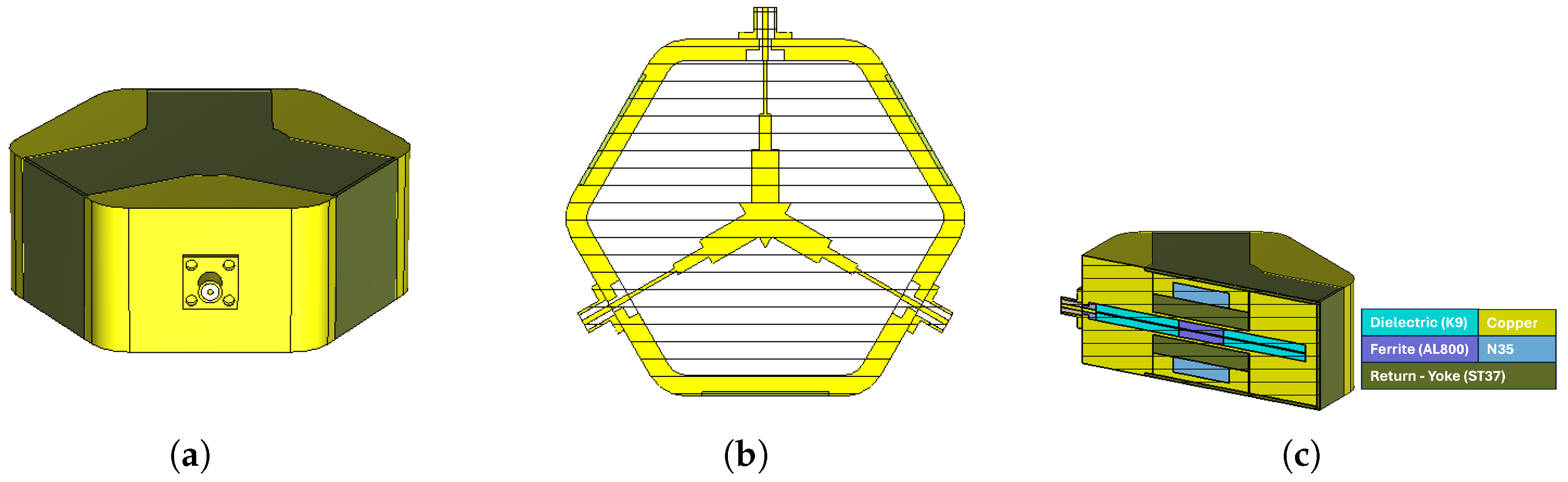
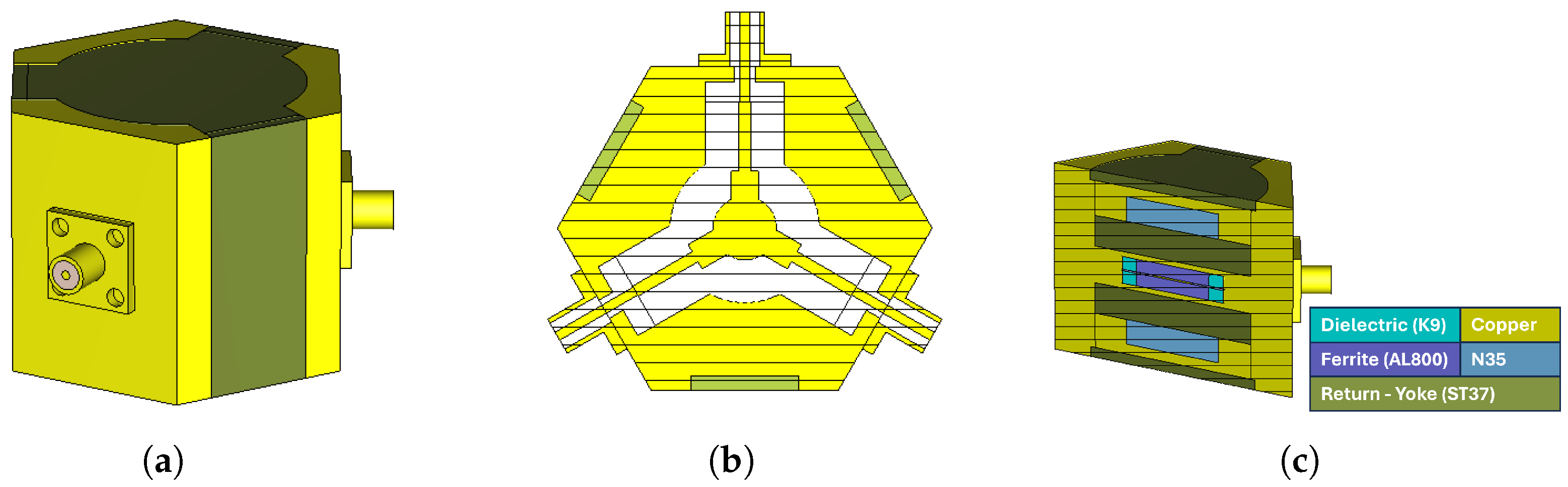
17]. The three-dimensional models of prototype-1 and prototype-2 are shown in
Figure 8 and
Figure 9, respectively. In both designs, permanent magnets with the same dimensions and specifications were used. The properties of the permanent magnets employed are summarized in
Table 8.
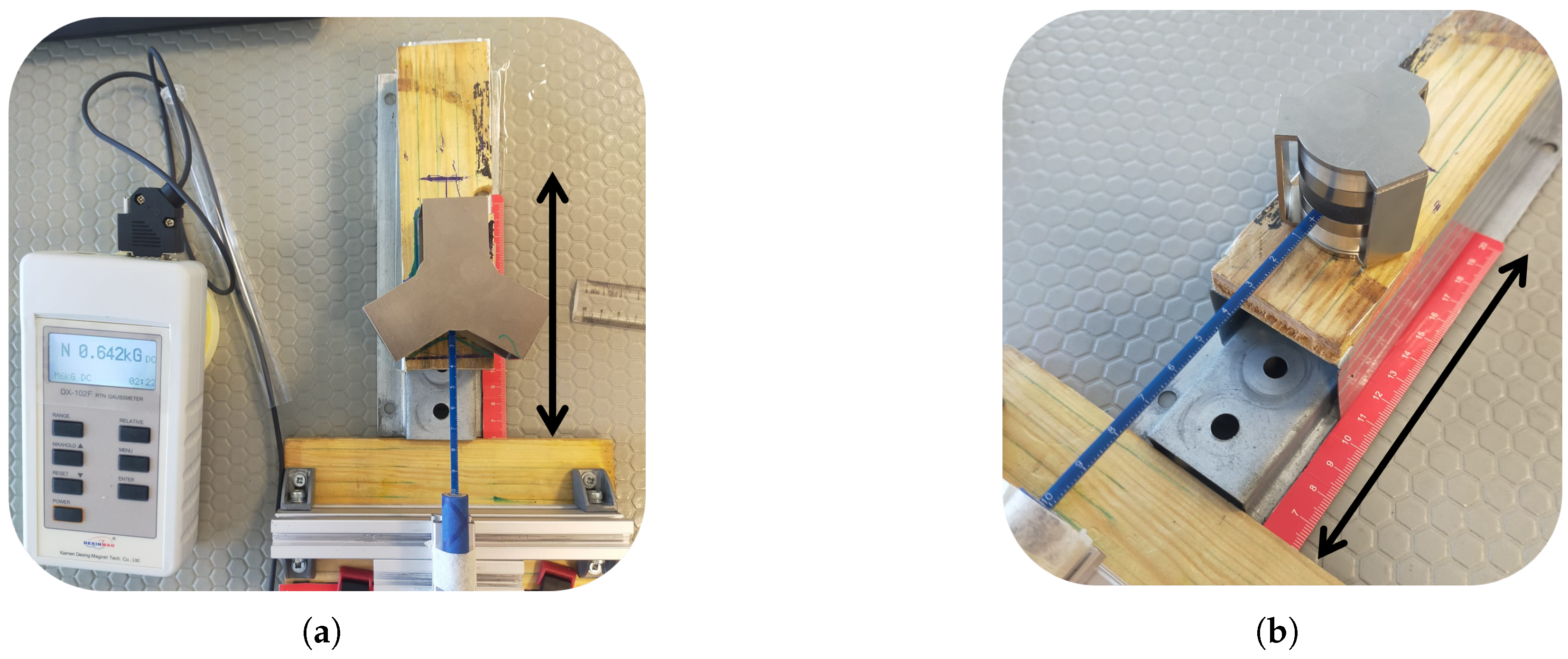
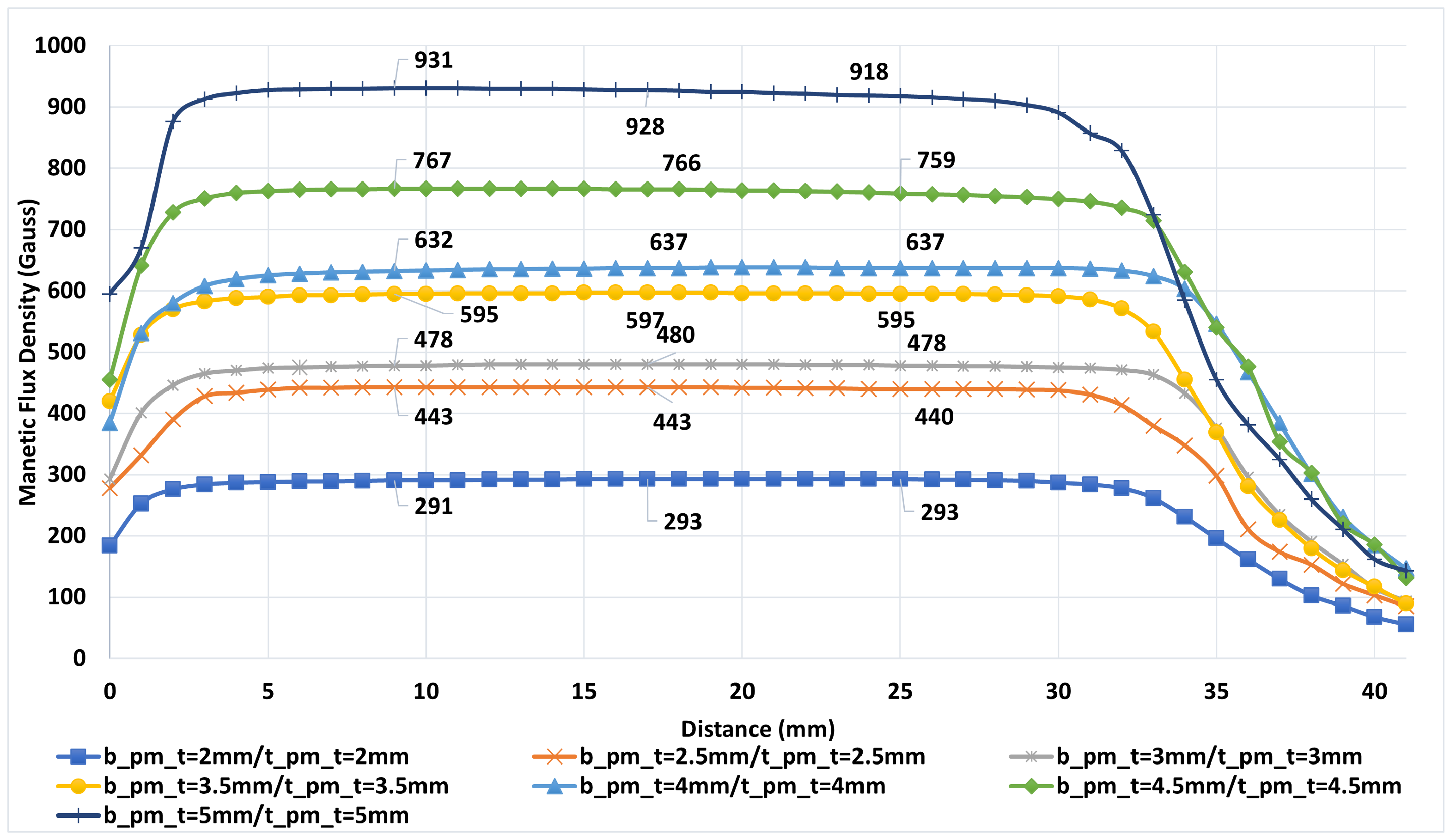
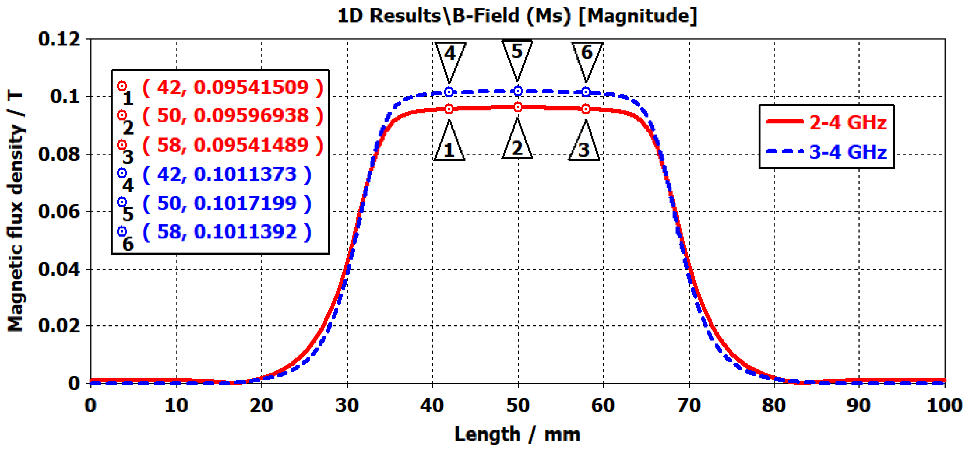
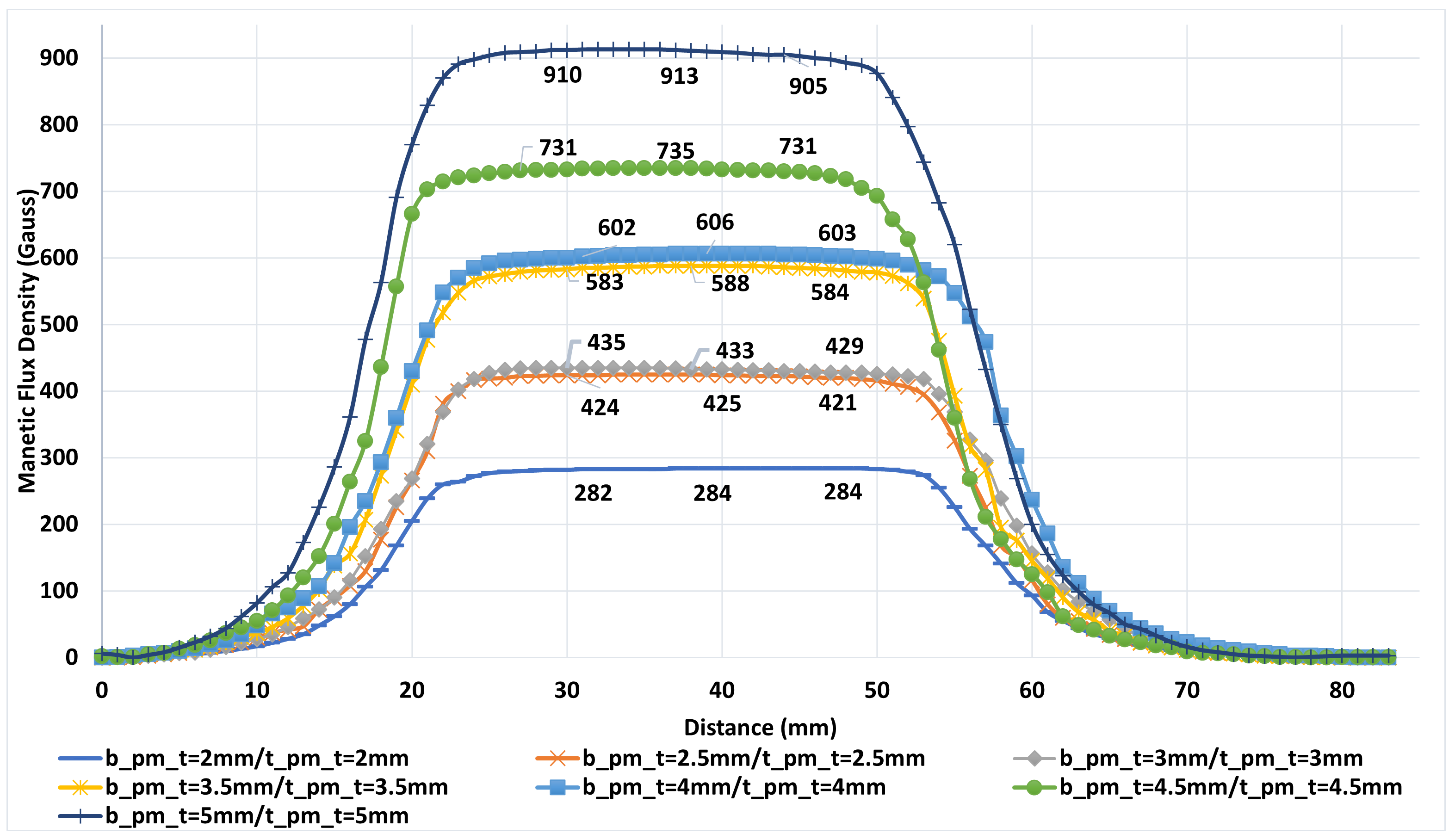
In ferrite materials, achieving high transmission and isolation requires a homogeneous magnetic field distribution. To obtain a more uniform magnetic field over the ferrite, soft steel (ST37) plates with relatively high magnetic permeability were incorporated into the design. The dimensions of these plates were selected as ⌀34.4/6 mm for prototype-1 and ⌀34/6.2 mm for prototype-2. The markers in
Figure 10 show the magnetic flux density at the edges and the center of the ferrite. Simulation results demonstrated that the magnetic field distribution in the ferrite region reached sufficient uniformity.
Following the magnetic field analyses, steady-state thermal simulations were performed for both proposed stripline circulator configurations to evaluate their thermal stability under high-power operating conditions. In these simulations, the electromagnetic loss distributions obtained from the frequency-domain solver were imported into the CST thermal solver and defined as volumetric heat sources. To represent the experimental high-power test conditions, a peak input power of 80 W, corresponding to an average power of approximately 40 W, was applied. The thermal material properties of the ferrite and dielectric layers, including thermal conductivity, density, and specific heat capacity, were assigned according to the parameters summarized in
Table 9. Manufacturer-provided values were used where available, while the remaining parameters were selected within ranges widely reported in the literature to ensure physically realistic modeling. The ambient temperature was fixed at 25 °C. To accurately represent the experimental operating conditions, an open boundary condition was employed, and a convective heat transfer coefficient of 20 W/m
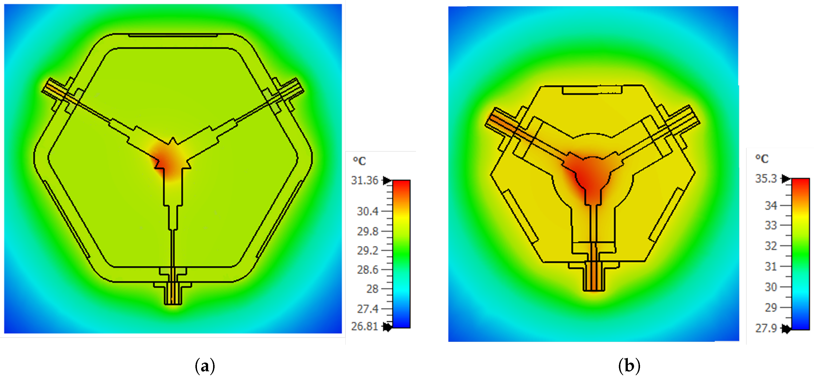
2K was applied only to the surfaces exposed to the ambient environment. Under these assumptions, steady-state thermal simulations were carried out, and the resulting temperature distributions of the proposed circulator structures are presented in
Figure 11.
For Prototype-1 (2–4 GHz,
Figure 11a), the steady-state thermal solver predicts a maximum temperature of 31.36 °C and a minimum temperature of 26.81 °C. With an ambient temperature of 25 °C, the corresponding peak temperature rise is approximately
°C. The hot spot is localized at the Y-junction center conductor region, coinciding with the area of maximum electromagnetic loss density. For Prototype-2 (3–4 GHz,
Figure 11b), the maximum temperature reaches 35.29 °C (approximately 35.16 °C on the selected cross-section), while the minimum temperature is 27.92 °C, resulting in a peak temperature rise of
°C. The elevated temperature level compared to Prototype-1 is consistent with the more compact geometry and increased loss concentration in the junction region. In both prototypes, the temperature distributions remain well within safe operating limits, and steady-state thermal equilibrium is achieved under natural air convection (
W/m
2K). These results are qualitatively consistent with the limited temperature rise observed during high-power experimental measurements.
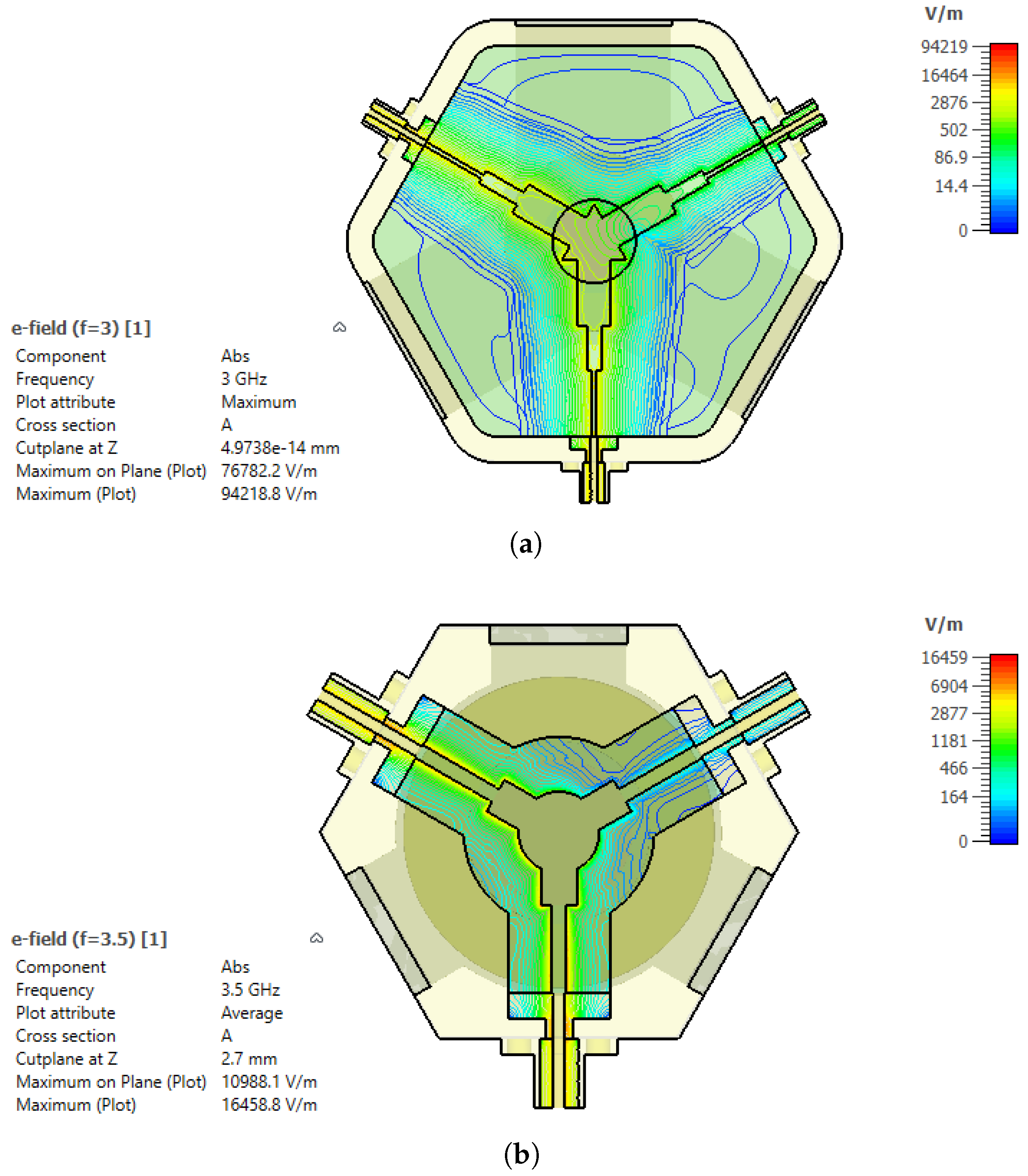
In addition to the thermal analysis, the electric-field distribution was evaluated to assess the breakdown limitation under high-power operation.
Figure 12 presents the simulated electric-field magnitude
at 3.5 GHz and 3 GHz. In both cases, the highest field intensities occur in the Y-junction center conductor region and at the SMA-to-stripline transition, where geometric discontinuities lead to field concentration. In linear passive microwave structures, the electric-field magnitude scales with the square root of the input power [
1,
13]. Therefore, the field level at an arbitrary input power
P can be obtained from a reference solution computed at
as
The simulated fields were normalized to a reference input power of
W using the frequency-domain solver [
17]. Using the worst-case frequency point at 3 GHz, the maximum electric-field magnitude from the frequency-domain simulation is
V/m. When scaled to the applied peak input power of 80 W, the maximum field becomes
The air breakdown threshold was conservatively taken as
MV/m, yielding a safety margin
Alternatively, the breakdown-limited peak input power can be estimated as
which is significantly higher than the applied power level. These results confirm that the proposed stripline circulator operates safely below the electric-field breakdown limit under the investigated high-power conditions. Before proceeding to the fabrication stage, the response of the proposed circulator designs to manufacturing tolerances, magnetic field variations, and uncertainties in material parameters was systematically evaluated. Magnetic field measurements performed on randomly selected samples from the same batch of permanent magnets revealed variations in the range of approximately 20–
, despite identical nominal specifications. Based on this measurement range, the influence of magnetic field-related uncertainties on the circulator performance was investigated by varying the applied DC bias magnetic field (
) within
around the nominal operating point in the simulations. In addition, to assess the effects of manufacturing and material-induced uncertainties, all components were considered within the CST Microwave Studio environment. The geometric parameters of the ferrite disk, dielectric layers, and center conductor—including thickness, effective length, and characteristic radius (or equivalent line width)—were modeled using random variations within a range of ±100 µ
to represent a realistic fabrication scenario. Furthermore, the relative permittivity of the dielectric material (
) was varied by
, while the saturation magnetization of the ferrite material (
) was adjusted within
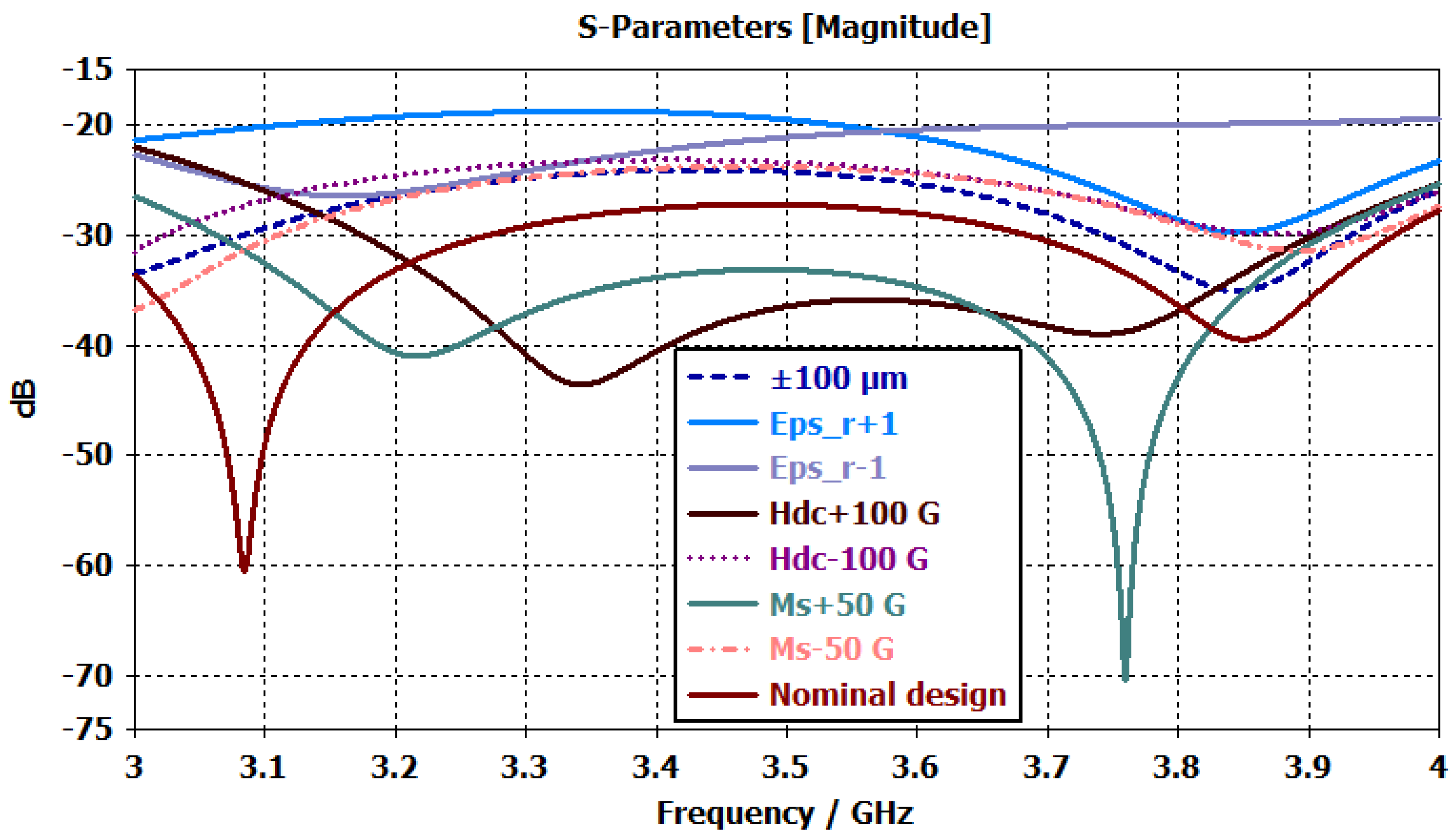
and incorporated into the tolerance analyses. The results of the tolerance analyses are presented in
Figure 13. The figure illustrates the variations in the input return loss characteristics of the circulator under geometric tolerances (±100 µ
), changes in dielectric permittivity (
), deviations in the DC bias magnetic field (
), and variations in ferrite saturation magnetization (
). The results indicate that variations in the dielectric permittivity have a pronounced impact on the return loss level across the operating band, whereas changes in the magnetic field and saturation magnetization primarily lead to localized shifts in resonance depth and frequency. In contrast, the influence of geometric tolerances remains comparatively limited with respect to the nominal design.
After the targeted performance values were achieved in the simulation stage, three-dimensional solid models were prepared for both circulators, and the fabrication process was initiated. In this context, the body structures were machined with high precision on CNC machines in accordance with the ISO 2768 tolerance standard [
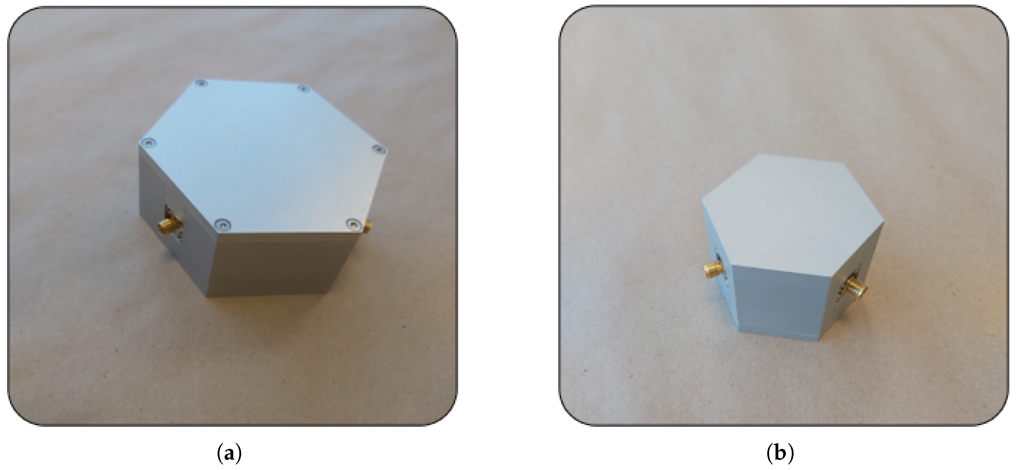
23] and the center conductor geometries were manufactured by wire EDM to satisfy the strict tolerance requirements. Assembly is a critical stage that directly influences device performance. For this reason, all components were mechanically fixed and precisely aligned to maintain structural symmetry. The center conductor and connector inputs were carefully soldered to ensure both mechanical integrity and electrical conductivity. In addition, the magnetic circuit elements were positioned accurately using mechanical fasteners. The assembled views of the circulators are shown in
Figure 14.