Abstract
A dual-band, compact, high-gain, simple geometry, wideband antenna for 5G millimeter-wave applications at 28 and 38 GHz is proposed in this paper. Initially, an antenna operating over dual bands of 28 and 38 GHz was designed. Later, a four-port Multiple Input Multiple Output (MIMO) antenna was developed for the same dual-band applications for high data rates, low latency, and improved capacity for 5G communication devices. To bring down mutual coupling between antenna elements, a parasitic element of simple geometry was loaded between the MIMO elements. After the insertion of the parasitic element, the isolation of the antenna improved by 25 dB. The suggested creation was designed using a Rogers/Duroid RT-5870 laminate with a thickness of 0.79 mm. The single element proposed has an overall small size of 13 mm × 15 mm, while the MIMO configuration of the proposed work has a miniaturized size of 28 mm × 28 mm. The parasitic element-loaded MIMO antenna offers a high gain of 9.5 and 11.5 dB at resonance frequencies of 28 GHz and 38 GHz, respectively. Various MIMO parameters were also examined, and the results generated by the EM tool CST Studio Suite® and hardware prototype are presented. The parasitic element-loaded MIMO antenna offers an Envelop Correlation Coefficient (ECC) < 0.001 and Channel Capacity Loss (CCL) < 0.01 bps/Hz, which are quite good values. Moreover, a comparison with existing work in the literature is given to show the superiority of the MIMO antenna. The suggested MIMO antenna provides good results and is regarded as a solid candidate for future 5G applications according to the comparison with the state of the art, results, and discussion.
1. Introduction
The main requirements for future 5G communication systems are high data rates, very low latency, high network capacity, wider availability, and multi-user support. To overcome these challenges, the antenna used in 5G devices plays a critical role [1]. Due to their high gain and wideband characteristics, Multiple Input Multiple Output (MIMO) antennae are thought to be the best candidates for meeting the aforementioned requirements [2]. A MIMO millimeter-wave antenna configuration offers high gain, a wide bandwidth, and high efficiency, resulting in a high data rate >20 Mbps and a low latency rate [3].
In recent years, MIMO technology has received much attention due to its numerous advantages, including increased data capacity, beam steering, and diversity. To obtain significantly better outcomes, the MIMO antenna’s various parameters have been adjusted in terms of isolation, gain, or Envelope Correlation Coefficient (ECC) and Channel Capacity Loss (CCL), etc. A variety of strategies are used to optimize these MIMO antenna characteristics [4]. The MIMO antenna’s isolation can be refined by adding an Electronic Bandgap (EBG), Retrodirective Antenna (RDA), metamaterial, Defected Ground Structure (DGS), shorting pins, or parasitic elements [5].
In the literature, a number of antenna designs are reported for millimeter bands [6,7,8,9,10,11,12], MIMO antennae for 5G communication [13,14,15,16,17,18,19,20,21], and MIMO antennae with improved isolation [22,23,24,25,26,27,28]. A single-element compact antenna for millimeter-wave dual-band applications was proposed to offer reconfigurability between 5G globally allocated bands 25 GHz and 50 GHz [6]. The approach of the phased array was also adopted to obtain a high-gain millimeter-wave antenna [7] or a simple and compact feed network array [8]. To avoid the complexity and the large size of the array, a compact antenna for 28/38 GHz has been reported for high-gain dual-band applications [9]. The Co-Planar waveguide (CPW) feed slot antenna for 28/38 GHz was reported with the advantages of easy fabrication, effective broadband performance, and low dispersion [10]. A broadband antenna operating over 28 GHz or 38 GHz or both was also reported, with a compact size and simple geometry [11,12]. The reported products have either offered a compact size or broadband with high gain. There is still a lack of high gain, as in most of the research, high gain is obtained by using an array approach or having a large size and more structural complexity.
As discussed before, a MIMO antenna can offer higher gain and a wider band to meet all the requirements discussed above for a 5G communication system [13,14]. The high data rate and large user capacity are granted by the high gain and wideband antenna [15]. In [16], a four-port MIMO system with general measurements of 100 mm × 75 mm × 0.258 mm is proposed for 28/38 GHz applications. The antenna has simple geometry but a large size as well as a narrow bandwidth of 0.7 GHz at 28 GHz. Another antenna for 28 GHz is reported in [17]. Although the reported product is minute in size (that is, 10 × 12 mm2), it has the demerit of low gain.
The air-filled, slot-structured antenna reported in [18] has a high gain of 6.9 dBi, operating at 28 GHz. Despite the fact that the reported product has a steep gain, it has a complex structure and high isolation. DGS is loaded to the ground plane to obtain a high gain and wideband antenna, but the literature notes that many incidents of energy are reflected back, which is not suitable and appropriate for smart device applications because microwave and millimeter-wave radiation can harm humans [19,20,21].
Mutual coupling is a key parameter of MIMO systems and plays a crucial role in obtaining a high data rate. Mutual coupling can be reduced by adopting various techniques, including DRA [22], EBG structures [23], metal strips [24], parasitic elements [25], metamaterials [26], or parasitic elements along with DGS [27]. A metamaterial-inspired DRA antenna with high isolation was reported in [22]. Although the isolation improved from −16 dB to −23 dB, there was not much improvement as compared to other reported work in the literature. In [23], double-sided EBG structures were inserted between MIMO elements to cut back the isolation from −52 dB to −60 dB. The reported antenna had a miniaturized size of 15.3 mm × 8.5 mm × 0.79 mm and high isolation, but its setback was the narrow bandwidth of 1 GHz at 28 GHz and 0.9 GHz at 38 GHz.
In [24], a metal strip was loaded between the elements of a MIMO antenna to reduce mutual coupling. The reported antenna offered a peak gain of 8.2 dBi but a narrow band ranging from 27.5 to 28.5 GHz and a complex structure. Mutual coupling by a C-shaped parasitic element was reported in [25]. The antenna offered a peak gain of 9.8 dBi but operated at 17 GHz, although it did show isolation improvement by using parasitic elements. Another product in [26] is reported for a 28/38 GHz application. The reported antenna has a small size of 25 mm × 15 mm × 1 mm, but complex geometry. A MIMO antenna for V2X communication was reported in [27] with a high isolation value of −60 dB. The antenna consisted of DGS and a parasitic element and was operational on the lower band of 5.6 GHz but is discussed here due to the technology used for mutual coupling reduction.
In this article, a compact, geometrically simple, high-gain, wideband antenna operating at 28/38 GHz is recommended for 5G applications. The four-element MIMO configuration is adopted to meet the requirements of future millimeter-wave 5G devices. In the final stage, a parasitic element is loaded between the MIMO antenna elements to cut back the mutual coupling. The remainder of the article is split as follows. In Section 2, the single element of the antenna along with the design stages, parametric analysis, and results are given. The MIMO antenna as well as the parasitic element-loaded MIMO antenna are discussed in Section 3, which also contains various results of the MIMO antenna and hardware prototype. The conclusion regarding the suggested antenna, along with references used in the literature, is provided in Section 4. A comparison table is given to compare the proposed antenna with those already published in the literature.
2. Single Element Wideband Antenna Operating at 28/38 GHz
2.1. Antenna Design
Figure 1 represents the geometrical configuration of the wideband compact antenna for millimeter-wave applications. The proposed antenna is embedded over commercially available substrate material Rogers/Duroid RT5870, with a relative permittivity and a loss tangent of 2.33 and 0.0012, respectively. The geometry of the proposed antenna contains a microstrip feedline and a rectangular patch loaded with a circular stub and slots. The proposed antenna has a compact size of AY × AX × H = 13 mm × 15 mm × 0.79 mm. The optimized parameters of the proposed dual-band antenna are given as follows: AX = 15; AY = 13; A1 = 3; A2 = 1.5; A3 = 6; A4 = 8; FX = 8; FY = 0.5; R1 = 2; R2 = 2.3; H = 0.79. All units are in millimeters (mm).
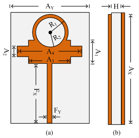
Figure 1.
Geometrical structure of the proposed wideband millimeter-wave antenna: (a) top view; (b) side view.
2.2. Antenna Design Stages
The wideband antenna suggested in this article has been designed for application at 28/38 GHz after following various design stages. Initially, the microstrip line rectangular patch antenna was engineered for use at 28 GHz. The equations below were used to determine the rectangular patch’s length (L) and width (W) [28].
where
L = Leff + 2 ΔL
In the next designing stage, an additional rectangular patch was inserted into the antenna, which caused the generation of second resonance along 43 GHz. The antenna after this stage resonated at 30 GHz with a return loss of −20 dB and at 43 GHz with a return loss of −15 dB. In the third stage, an additional circular shaped patch was loaded on top of the existing rectangular radiator, which improved the return loss as well as lowering the higher resonance mode at 38 GHz. In the final stage, a circular slot of radius R2 = 2.3 mm was etched from the radiator of the antenna, as given in Figure 2a, which resulted in shifts in a frequency band and improved the return loss. The resultant antenna after the final step operated at 26.5–31.5 GHz and 35–41 GHz, as depicted in Figure 2a,b.
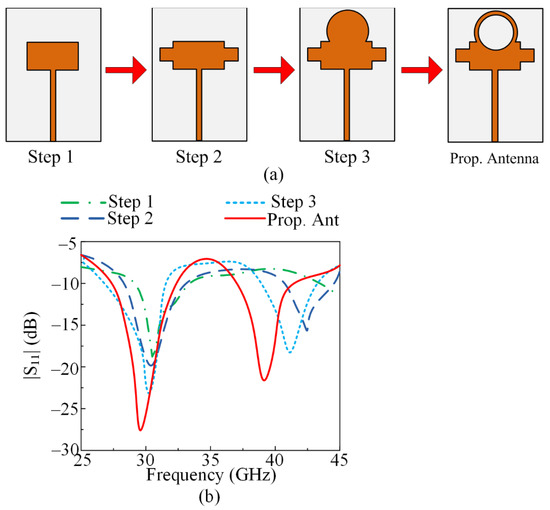
Figure 2.
(a) Design evolution of proposed dual-band antenna and (b) S-parameter graph of various design steps.
2.3. Single Element Antenna Results and Discussions
To validate the dual-band antenna simulation-based results for mm-wave applications, a hardware prototype was fabricated and measured. Various results in terms of the scattering parameters, gain, and radiation patterns are discussed below.
2.3.1. Measured and Simulated S-Parameter
The suggested dual-band antenna’s measured and simulated S-parameters are shown in Figure 3. The antenna provides two bands: one at 28 GHz with an impedance bandwidth between 26 and 31.5 GHz, and another at 38 GHz with an impedance bandwidth between 36.5 and 41.7 GHz. Moreover, the figure shows the similarity between the S-parameters generated from software and the tested prototype, which makes the suggested antenna a good candidate for future 28/38 GHz applications.
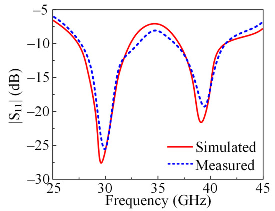
Figure 3.
S-parameter plot of a proposed dual-band antenna operating at 28 GHz and 38 GHz, measured and simulated.
2.3.2. Measured and Simulated Gain
In Figure 4, the measured gain of the antenna prototype along with a comparison with the simulated gain is given. It can be noticed that the antenna offers a gain of >7 dBi at an operational bandwidth of 26–31.5 GHz, with a peak value of 8 dB at the resonance frequency of 28 GHz. Meanwhile, the antenna offers a gain of >8.25 dBi at an operational bandwidth of 36.5–41.7 GHz, with a peak value of 9 dB at the resonance frequency of 38 GHz. Moreover, the figure shows good settlement between the software-generated results and the hardware-measured results, which makes the proposed antenna a good and suitable candidate for future high-gain 5G applications.
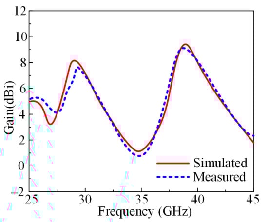
Figure 4.
Measured and simulated gain of proposed dual-band antenna.
2.3.3. Measured and Simulated Radiation Pattern
Figure 5 depicts the radiation pattern at resonance frequencies of 28 GHz and 38 GHz. The suggested wideband millimeter-wave antenna revealed a broadside radiation pattern in the theoretical E-plane (θ = 0°) in contrast to the butterfly-shaped pattern that was examined in the H-plane (θ = 90°). In general, there is good agreement between the measured and simulated E-plane and H-plane data for both resonance frequencies.
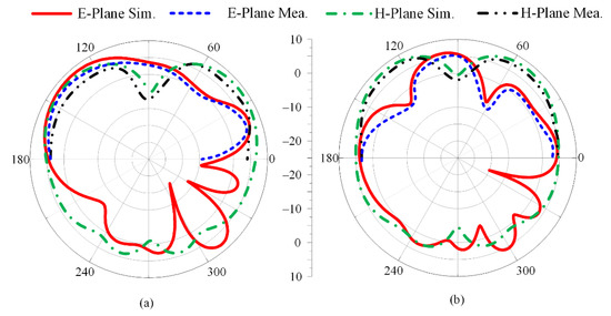
Figure 5.
Measured and simulated radiation pattern of proposed dual-band antenna at (a) 28 GHz and (b) 38 GHz.
The suggested dual-band antenna is compared in Table 1 to previous antennas in the literature on the same frequency range. The overall size of the antenna, operational bandwidth, operating frequency, and gain are compared. The table shows that the suggested antenna is small in size compared to the others proposed in [8,9,12] and offers dual bands with a wide bandwidth and high gain. Although the antennae presented in [6,10,11] offer a compact size, they only have simulated results, which limits their useability in practical application. From the above results, discussion, and comparison with the literature, it is demonstrated that the suggested antenna is an excellent candidate for upcoming millimeter-wave applications.

Table 1.
Comparison of proposed dual-band antenna with the state of the art.
3. MIMO Configuration of Proposed Antenna
3.1. MIMO Antenna Design Procedure
The proposed dual-band antenna’s MIMO arrangement for operation at 28/38 GHz is shown in Figure 6. The proposed MIMO antenna system contains four elements in an orthogonal pattern with a full ground plane on the backside. The MIMO system has an overall size of MX × MY = 28 mm × 28 mm. The parasitic element is placed at the center of the antenna to reduce mutual coupling within the antenna, as given in Figure 6. The MIMO antenna system was designed by rotating the 90° antenna element on the z-axis. The size of the substrate was increased due to the MIMO configuration; the rest of the antenna parameters are the same as for the single antenna element discussed in Section 2 and given in Figure 1. The optimal parameters of the MIMO antenna and parasitic element are given as follows: MX = 28; MY = 28; M1 = 4.65; M2 = 13.2; P1 = 6.4; P2 = 1.35; RP = 3.25 (all units are in millimeters (mm)).
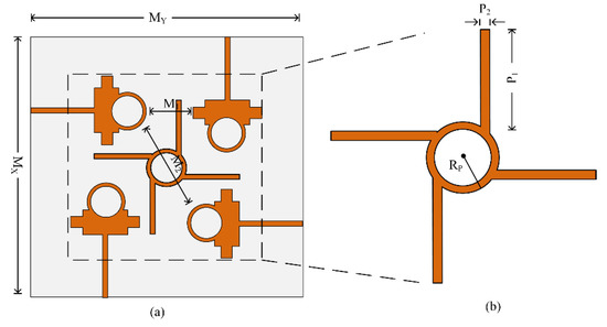
Figure 6.
Proposed parasitic element loaded MIMO antenna: (a) top view; (b) parasitic element.
Figure 7 exhibits the four-port MIMO antenna system with and without the parasitic element, while the ground plane is unchanged in both cases. The parasitic element is introduced between elements of the MIMO system to overcome the amount of energy generated by nearby elements when another element radiates. This effect of one element of the MIMO system on another is also called mutual coupling. The reduction in mutual coupling can also be expressed by the following equations given in [29]:
where dij expresses the space between the ith and jth elements, N represents the number of array components, and is the fine-structure constant having a value approximately equal to 0.00729735. The comparison of transmission coefficients in terms of the antenna effect by adjacent antenna elements (S12, S23, S34, S41) and diagonal elements (S24, S31) is given in Figure 8. The MIMO antenna system without a parasitic element offered a maximum value of −25 dB at 28 GHz and −36 dB at 40 GHz under the effect of diagonal elements. Meanwhile, under adjacent elements, the antenna offered a maximum of −40 dB at 32 GHz and −35 dB at 41 GHz. After placing the parasitic element, the antenna offered a minimum value <−30 dB for both cases, with maximum values of −45 dB and −50 dB at 31 GHz and 39 GHz, respectively. The comparison of mutual coupling with and without the parasitic element is given in Figure 8.
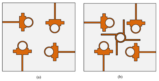
Figure 7.
MIMO design evolution: (a) without parasitic element; (b) with parasitic element.
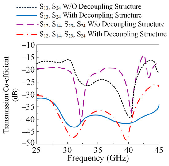
Figure 8.
Comparison plot of transmission coefficient with and without parasitic element.
3.2. MIMO Antenna Performance Parameter
To verify the simulated results generated by the software tool, a hardware prototype was fabricated, as given in Figure 9. To analyze and verify the transmission and reflection coefficient, the 220 ZVA Vector Network Analyzer (VNA) by Rohde & Schwarz was used.
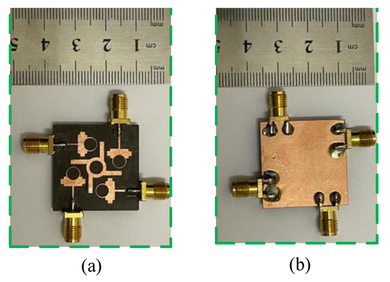
Figure 9.
Hardware prototype of proposed parasitic element-loaded 4-port MIMO antenna for 28/38 GHz millimeter-wave applications (a) top side (b) bottom side.
3.2.1. Reflection Coefficient
The simulated and hardware-measured reflection coefficients of the proposed parasitic element-loaded wideband antenna for 28/38 GHz applications are depicted in Figure 10. It can be observed that the proposed antenna offers dual bands at 28.5 GHz and 38.5 GHz having impedance bandwidths of 26.5–31.5 GHz and 36–41.7 GHz, respectively. The proposed parasitic element-loaded MIMO antenna operates at a low value of return loss <−20 dB for both resonance bands. Moreover, the simulated and measured results show strong agreement, with negligible changes. This similarity in the simulated and measured results and the dual wideband operation make the proposed antenna a suitable design for future 5G millimeter-wave applications.
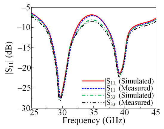
Figure 10.
Comparison of measured and simulated reflection coefficients with parasitic element.
3.2.2. Transmission Coefficient
Figure 11 presents the measured and simulated transmission coefficients of the suggested parasitic element-loaded four-port MIMO system. It can be noticed from the provided figure that the antenna offers isolation of <−35 dB in the operational bandwidth region, with a minimum value of −48 dB at 31 GHz and 39 GHz. The results are provided for the antenna element with its nearby antenna and diagonal antenna for better understanding. The mutual coupling was reduced by placing the parasitic element between the MIMO antenna elements as discussed earlier. The simulated results show strong similarity with the measured results, which makes the proposed antenna a good candidate for future millimeter-wave devices.
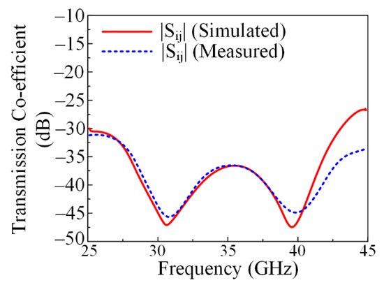
Figure 11.
Comparison of measured and simulated transmission coefficients with parasitic element.
3.2.3. Radiation Pattern
The radiation pattern of the proposed parasitic element-loaded four-port MIMO antenna is given in Figure 12 at the resonance frequency bands of 28 GHz and 38 GHz. It can be noticed that the suggested antenna for mm-wave application provides a broadside radiation pattern at the principal E-plane and a slightly distorted radiation pattern at the H-plane. The distortion in the radiation pattern is due to multiple stub insertions and slots etched from the radiating patch. Moreover, similarity is observed between the measured and simulated results, which makes the proposed MIMO antenna system a potential and suitable applicant for 5G millimeter-wave application.
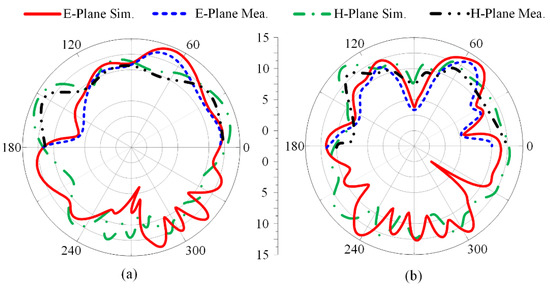
Figure 12.
Measured and simulated radiation patterns of proposed parasitic element-loaded dual-band MIMO antenna at (a) 28 GHz and (b) 38 GHz.
3.2.4. Envelop Correlation Coefficient (ECC)
The Envelop Correlation Coefficient (ECC) measures the performance of one antenna element. The ECC of the MIMO antenna can be measured in terms of the S-parameter and the far-filed radiation pattern. The ECCs of the adjustment element and diagonal element are given in Figure 13. The suggested antenna delivers an ECC < 0.001, as can be seen in the figure below, for both operational bandwidths in the case of the nearby antenna element and the diagonal element. The mathematical equations for measuring the ECC are given below [30]:
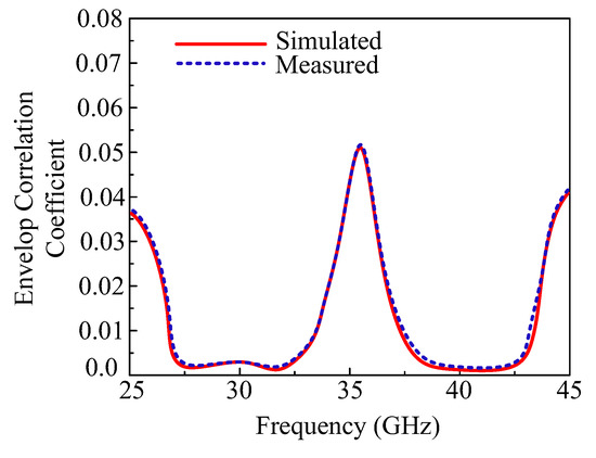
Figure 13.
Envelop Correlation Coefficient (ECC) of the proposed parasitic element-loaded dual-band MIMO antenna.
The above equation expresses the general form to calculate the ECC, where i and j are the antenna elements of a MIMO system.
3.2.5. Diversity Gain (DG)
For the MIMO antenna system, when a diversity scheme is performed, losses occur in the form of transmission power. These losses were analyzed by studying Diversity Gain (DG). For an ideal scenario, DG must be equal to 10 dB, but for an actual scenario, values close to 10 dB are considered. The proposed antenna showed a DG around 9.99 dB for both the operational bands, as given in Figure 14. Mathematically, DG can be expressed as follows [30]:
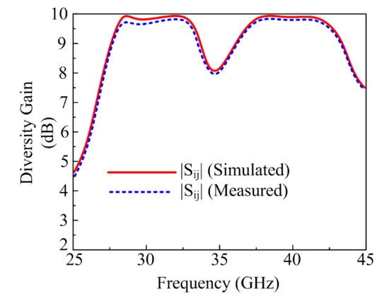
Figure 14.
Diversity Gain (DG) of the proposed parasitic element-loaded dual-band MIMO antenna.
3.2.6. Channel Capacity Loss (CCL)
To check the performance of the MIMO antenna system, Channel Capacity Loss (CCL) is at the leading edge. CCL occurs in the MIMO system due to correlation losses. The proposed parasitic element-loaded four-port MIMO antenna offers around 0.01 bps/Hz for both operating bandwidths of 28 GHz and 38 GHz, as provided in Figure 15. The acceptable range of CCL is <0.5 bps/Hz, and the mathematical equation to calculate it is given below [31]:
where
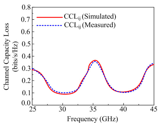
Figure 15.
Channel Capacity Loss (CCL) of the proposed parasitic element-loaded dual-band MIMO antenna.
3.2.7. Mean Effective Gain (MEG)
Mean Effective Gain (MEG) represents the power received in a fading environment by any wireless system. For any MIMO antenna system, the fair range of MEG is <−3 dBi. The proposed antenna showed an MEG < −5.5 dBi at both operational bandwidths, as given in Figure 16. Moreover, the mathematical equation to calculate the MEG is given below [31]:
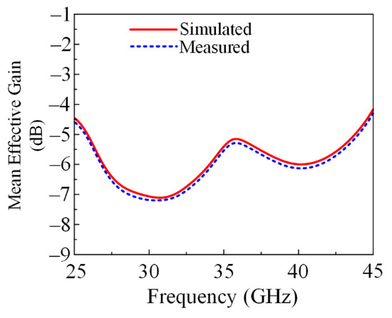
Figure 16.
Mean Effective Gain (MEG) of the proposed parasitic element-loaded dual-band MIMO antenna.
In the above equation, represents the angular density function of incident power and XPR is the cross-polarization power ratio [32].
In Table 2, a comparison between the proposed four-port MIMO antenna and previous research is provided. From the below table, it is clear that the suggested MIMO antenna system has a compact size, offers wide dual bandwidths, offers high gain, and has reduced mutual coupling with the simple parasitic element shape. The comparison table, the discussion, and the results above indicate that the proposed antenna is a potential dominant candidate for future compact, high-gain, broadband 5G portable devices.
Table 2.
Comparison of the proposed parasitic element-loaded MIMO antenna for isolation improvement with the state of the art.
4. Conclusions
In this article, a four-port MIMO antenna loaded with a parasitic element has been presented. A rectangular patch antenna was initially created for 28 GHz applications. The rectangular patch antenna’s slot was engraved and various stubs were loaded to create a dual-band 28/38 GHz antenna with a large operational bandwidth and minimal return losses. Later on, configuration of a four-port MIMO was performed with a parasitic element to cut back mutual coupling among the four MIMO antenna elements. The parasitic element-loaded MIMO antenna has a compact size and simple geometry and operates over a wide bandwidth of 26.5–31.5 GHz with a resonance frequency of 28 GHz and 36–41.7 GHz with a resonance frequency of 38 GHz. Stringent agreement between the simulated and measured findings was seen. A hardware prototype was created to verify the simulated results. The MIMO parameters ECC, CCL, DG, and MEG were also studied to analyze the antenna. The parasitic element-loaded MIMO antenna had an ECC of <0.001, CCL of <0.01 bps/Hz, DG of around 9.99 dBi, and MEG of <−5.5 days. The existing literature was compared with the MIMO antenna results, which further indicated that the suggested antenna outperforms the related antennae, making it a strong candidate for future 5G applications.
Author Contributions
Conceptualization, methodology, and software, M.H., W.A.A. and E.M.A.; validation, M.S.A., M.A. and M.F.A.S.; writing—original draft preparation, M.H., E.M.A., M.S.A. and M.A.; writing—review and editing, W.A.A., D.H.E., M.F.A.S. and A.A.; funding acquisition, D.H.E. and A.A. All authors have read and agreed to the published version of the manuscript.
Funding
This work is supported by Princess Nourah bint Abdulrahman University Researchers Supporting Project number (PNURSP2022R238), Princess Nourah bint Abdulrahman University, Riyadh, Saudi Arabia.
Institutional Review Board Statement
Not applicable.
Informed Consent Statement
Not applicable.
Data Availability Statement
Not applicable.
Conflicts of Interest
The authors declare no conflict of interest.
References
- Fatah, S.Y.A.; Hamad, E.K.; Swelam, W.; Allam, A.M.M.A.; Sree, M.F.A.; Mohamed, H.A. Design and implementation of UWB slot-loaded printed antenna for microwave and millimeter wave applications. IEEE Access 2021, 9, 29555–29564. [Google Scholar] [CrossRef]
- Ibrahim, A.A.; Abo Sree, M.F. UWB MIMO antenna with 4-element, compact size, high isolation and single band rejection for high-speed wireless networks. Wirel. Netw. 2022, 28, 3143–3155. [Google Scholar] [CrossRef]
- Zahra, H.; Awan, W.A.; Ali, W.A.E.; Hussain, N.; Abbas, S.M.; Mukhopadhyay, S. A 28 GHz broadband helical inspired end-fire antenna and its MIMO configuration for 5G pattern diversity applications. Electronics 2021, 10, 405. [Google Scholar]
- Hussain, N.; Kim, N. Integrated Microwave and mm-Wave MIMO Antenna Module with 360° Pattern Diversity For 5G Internet-of-Things. IEEE Internet Things J. 2022. [Google Scholar] [CrossRef]
- Taha, A.; Allam, A.M.M.A.; Wahba, W.; Sree, M.F.A. Printed Ridge Gap Waveguide Based Radome Antenna for K-Ka Applications. In Proceedings of the 15th European Conference on Antennas and Propagation (EuCAP), Virtual. 22–26 March 2021; pp. 1–5. [Google Scholar]
- Awan, W.A.; Zaidi, A.; Hussain, N.; Khalid, S.; Baghdad, A. Characterization of dual band MIMO antenna for 25 GHz and 50 GHz applications. In Proceedings of the International Conference on Computing, Electronic and Electrical Engineering (ICE Cube), Quetta, Pakistan, 12–13 November 2018; IEEE: Piscataway, NJ, USA, 2018; pp. 1–4. [Google Scholar]
- Ibrahim, A.A.; Zahra, H.; Dardeer, O.M.; Hussain, N.; Abbas, S.M.; Abdelghany, M.A. Slotted Antenna Array with Enhanced Radiation Characteristics for 5G 28 GHz Communications. Electronics 2022, 11, 2664. [Google Scholar] [CrossRef]
- Tahseen, H.U.; Zheng, Z.; Yang, L. A Single Substrate 38 GHz Dual Antenna Array with Compact Feed Network. IEEJ Trans. Elect. Electron. Eng. 2021, 16, 1203–1208. [Google Scholar] [CrossRef]
- Jilani, S.F.; Alomainy, A. A multiband millimeter-wave 2-D array based on enhanced Franklin antenna for 5G wireless systems. IEEE Antennas Wirel. Propag. Lett. 2017, 16, 2983–2986. [Google Scholar] [CrossRef]
- Ali, M.M.M.; Sebak, A.R. Dual band (28/38 GHz) CPW slot directive antenna for future 5G cellular applications. In Proceedings of the IEEE International Symposium on Antennas and Propagation (APSURSI), El Conquistador, Puerto Rico, 26 June–1 July 2016; pp. 399–400. [Google Scholar]
- Przesmycki, R.; Bugaj, M.; Nowosielski, L. Broadband microstrip antenna for 5G wireless systems operating at 28 GHz. Electronics 2020, 10, 1. [Google Scholar] [CrossRef]
- Hussain, M.; Jarchavi, S.M.R.; Naqvi, S.I.; Gulzar, U.; Khan, S.; Alibakhshikenari, M.; Huynen, I. Design and Fabrication of a Printed Tri-Band Antenna for 5G Applications Operating across Ka-, and V-Band Spectrums. Electronics 2021, 10, 2674. [Google Scholar] [CrossRef]
- Marzouk, H.M.; Ahmed, M.I.; Shaalan, A.H.A. Novel dual-band 28/38 GHz MIMO antennas for 5G mobile applications. Prog. Electromag. Res. C 2019, 93, 103–117. [Google Scholar] [CrossRef]
- Farahat, A.E.; Hussein, K.F.A. 28/38 GHz dual-band Yagi-Uda antenna with corrugated radiator and enhanced reflectors for 5G MIMO antenna systems. Prog. Electromag. Res. C 2020, 101, 159–172. [Google Scholar] [CrossRef]
- El Hadri, D.; Zakriti, A.; Zugari, A.; El Ouahabi, M.; El Aoufi, J. High isolation and ideal correlation using spatial diversity in a compact MIMO antenna for fifth-generation applications. Int. J Antennas Propag. 2020, 2020, 1–10. [Google Scholar] [CrossRef]
- Alnemr, F.; Ahmed, M.F.A.; Shaalan, A.A. A compact 28/38 GHz MIMO circularly polarized antenna for 5 G applications. J. Infrared Millim. Terahertz Waves 2021, 42, 338–355. [Google Scholar] [CrossRef]
- Hasan, M.N.; Seo, M. Compact omnidirectional 28 GHz 2 × 2 MIMO antenna array for 5G communications. In Proceedings of the International Symposium on Antennas and Propagation (ISAP), Busan, Korea, 23–26 October 2018. [Google Scholar]
- Usman, M.; Kobal, E.; Nasir, J.; Zhu, Y.; Yu, C.; Zhu, A. Compact SIW fed dual-port single element annular slot MIMO antenna for 5G mmWave applications. IEEE Access 2021, 9, 91995–92002. [Google Scholar] [CrossRef]
- Hussain, M.; Ali, E.M.; Jarchavi, S.M.R.; Zaidi, A.; Najam, A.I.; Alotaibi, A.A.; Ghoneim, S.S. Design and Characterization of Compact Broadband Antenna and Its MIMO Configuration for 28 GHz 5G Applications. Electronics 2022, 11, 523. [Google Scholar] [CrossRef]
- Liu, P.; Zhu, X.W.; Zhang, Y.; Wang, X.; Yang, C.; Jiang, Z.H. Patch antenna loaded with paired shorting pins and H-Shaped slot for 28/38 GHz dual-band MIMO applications. IEEE Access 2020, 8, 23705–23712. [Google Scholar] [CrossRef]
- Farahat, A.E.; Hussein, K.F. Dual-band (28/38 GHz) MIMO antenna system for 5G mobile communications with efficient DoA estimation algorithm in noisy channels. Appl. Comput. Electromagn. Soc. J. 2021, 36, 282–294. [Google Scholar] [CrossRef]
- Murthy, N. Improved isolation metamaterial inspired mm-Wave MIMO dielectric resonator antenna for 5G application. Prog. Electromagn. Res. C 2020, 100, 247–261. [Google Scholar] [CrossRef]
- Tu, D.T.T.; Phuong, N.T.B.; Son, P.D.; Van Yem, V. Improving Characteristics of 28/38GHz MIMO Antenna for 5G Applications by Using Double-Side EBG Structure. J. Commun. 2019, 14, 1–8. [Google Scholar] [CrossRef]
- Zhang, Y.; Deng, J.Y.; Li, M.J.; Sun, D.; Guo, L.X. A MIMO dielectric resonator antenna with improved isolation for 5G mm-wave applications. IEEE Antennas Wirel. Propag. Lett. 2019, 18, 747–751. [Google Scholar] [CrossRef]
- Yon, H.; Rahman, N.H.A.; Aris, M.A.; Jamaluddin, M.H.; Lin, I.K.C.; Jumaat, H.; Redzwan, F.N.M.; Yamada, Y. Development of C-Shaped Parasitic MIMO Antennas for Mutual Coupling Reduction. Electronics 2021, 10, 2431. [Google Scholar] [CrossRef]
- Alanazi, M.D.; Khamas, S.K. A Compact Dual Band MIMO Dielectric Resonator Antenna with Improved Performance for mm-Wave Applications. Sensors 2022, 22, 5056. [Google Scholar] [CrossRef] [PubMed]
- Awan, W.A.; Soruri, M.; Alibakhshikenari, M.; Limiti, E. On-Demand Frequency Switchable Antenna Array Operating at 24.8 and 28 GHz for 5G High-Gain Sensors Applications. Prog. Electromag. Res. M 2022, 108, 163–173. [Google Scholar] [CrossRef]
- Balanis, C.A. Antenna Theory: Analysis and Design, 3rd ed.; Wiley: Hoboken, NJ, USA, 2005; pp. 811–820. [Google Scholar]
- Ali, A.; Tong, J.; Iqbal, J.; Illahi, U.; Rauf, A.; Rehman, S.U.; Ali, H.; Qadir, M.M.; Khan, M.A.; Ghoniem, R.M. Mutual Coupling Reduction through Defected Ground Structure in Circularly Polarized, Dielectric Resonator-Based MIMO Antennas for Sub-6 GHz 5G Applications. Micromachines 2022, 13, 1082. [Google Scholar] [CrossRef] [PubMed]
- Chouhan, S.; Panda, D.K.; Gupta, M.; Singhal, S. Multiport MIMO antennas with mutual coupling reduction techniques for modern wireless transreceive operations: A review. Int. J. RF Microw. Comput. Aided Eng. 2018, 28, 21189. [Google Scholar] [CrossRef]
- Jabire, A.H.; Ghaffar, A.; Li, X.J.; Abdu, A.; Saminu, S.; Alibakhshikenari, M.; Falcone, F.; Limiti, E. Metamaterial based design of compact UWB/MIMO monopoles antenna with characteristic mode analysis. Appl. Sci. 2021, 11, 1542. [Google Scholar] [CrossRef]
- Faouri, Y.; Ahmad, S.; Naseer, S.; Alhammami, K.; Awad, N.; Ghaffar, A.; Hussein, M.I. Compact Super Wideband Frequency Diversity Hexagonal Shaped Monopole Antenna with Switchable Rejection Band. IEEE Access 2022, 10, 42321–42333. [Google Scholar] [CrossRef]
Publisher’s Note: MDPI stays neutral with regard to jurisdictional claims in published maps and institutional affiliations. |
© 2022 by the authors. Licensee MDPI, Basel, Switzerland. This article is an open access article distributed under the terms and conditions of the Creative Commons Attribution (CC BY) license (https://creativecommons.org/licenses/by/4.0/).