
Resistance Switching in Polycrystalline C12A7 Electride
 , , ,
, , ,  ,
, 
Abstract
1. Introduction
2. Fabrication Technique and Characterization Methods
3. Results
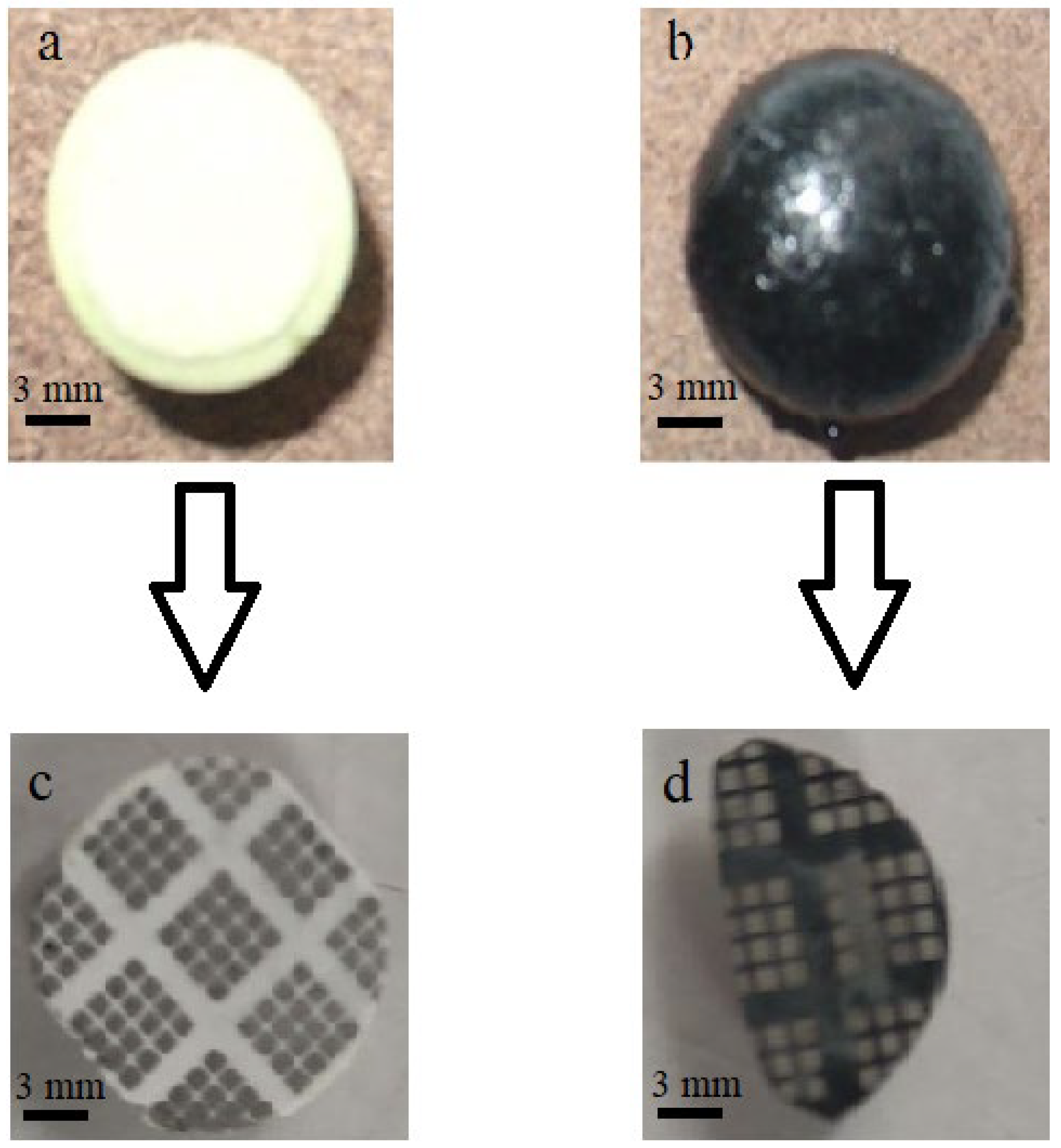
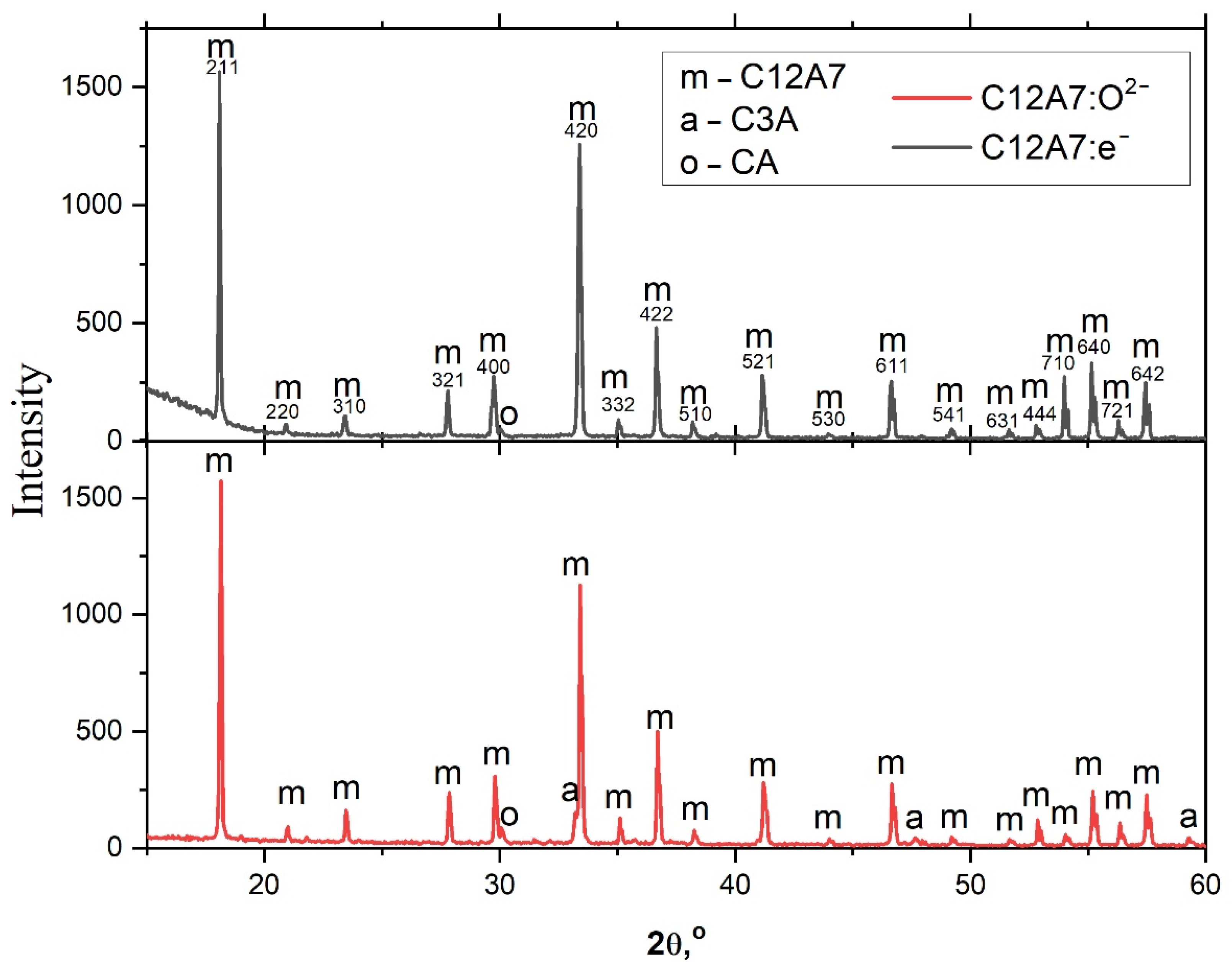
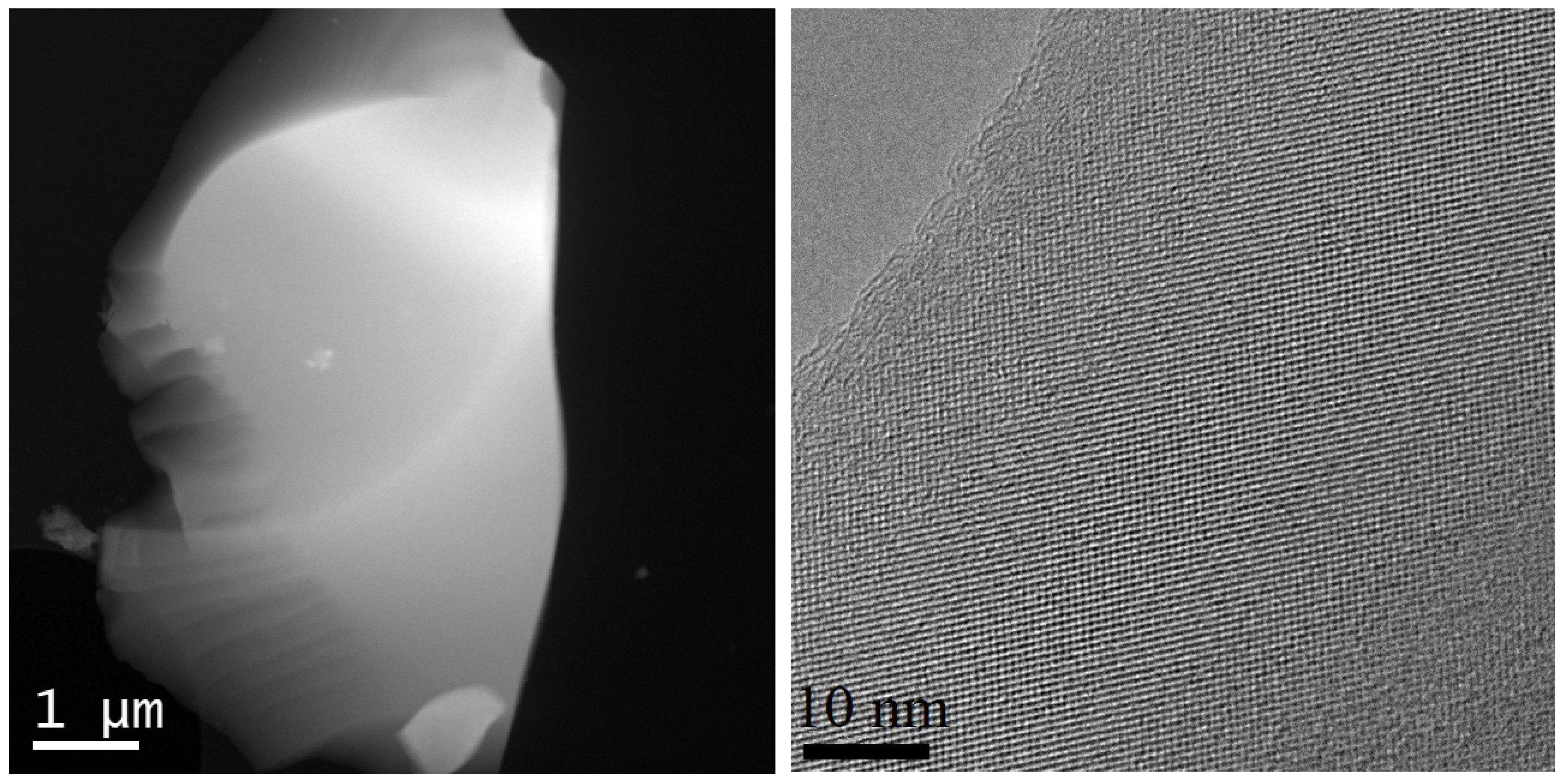
3.1. XRD and TEM Studies
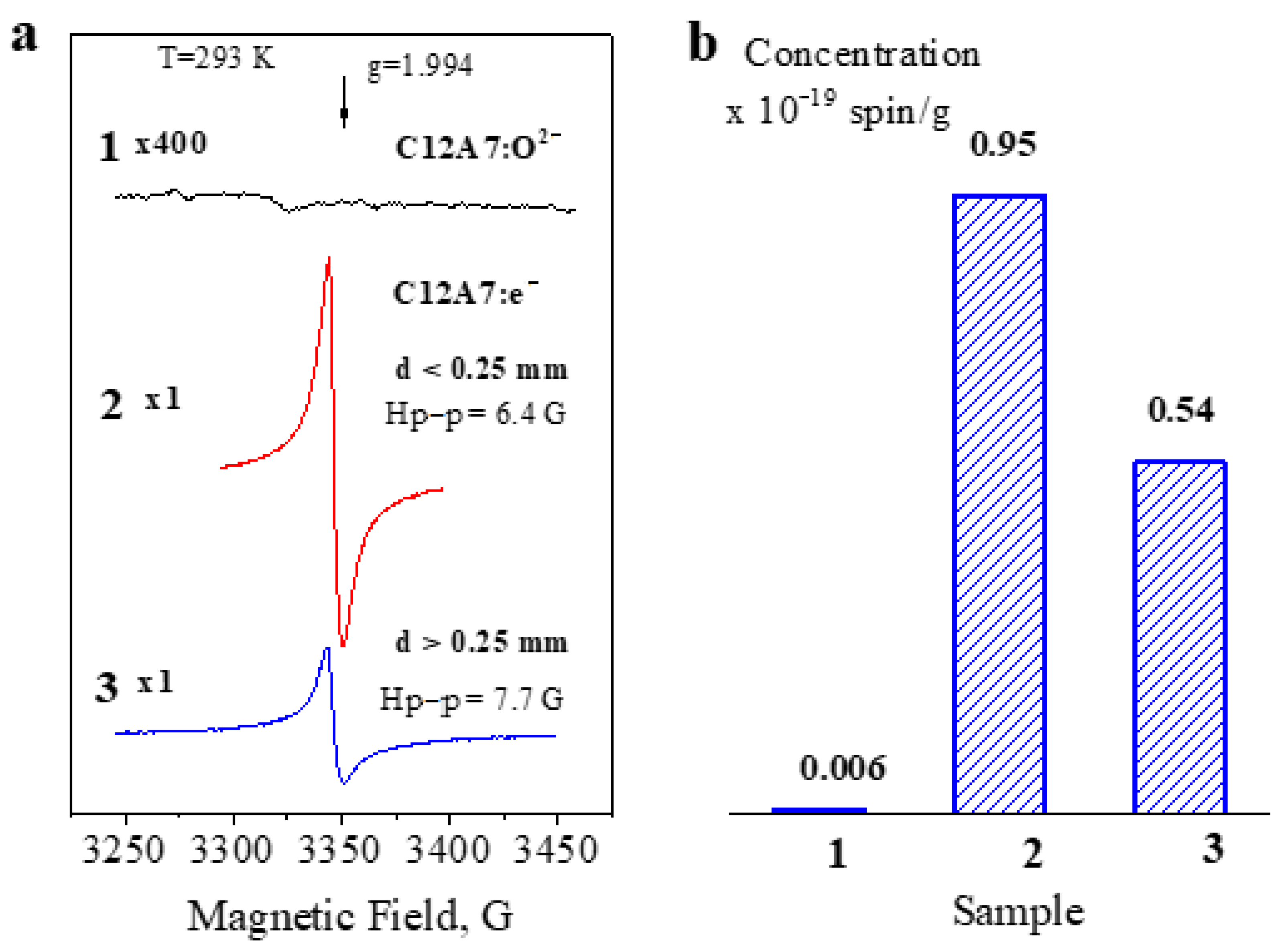
3.2. EPR Studies
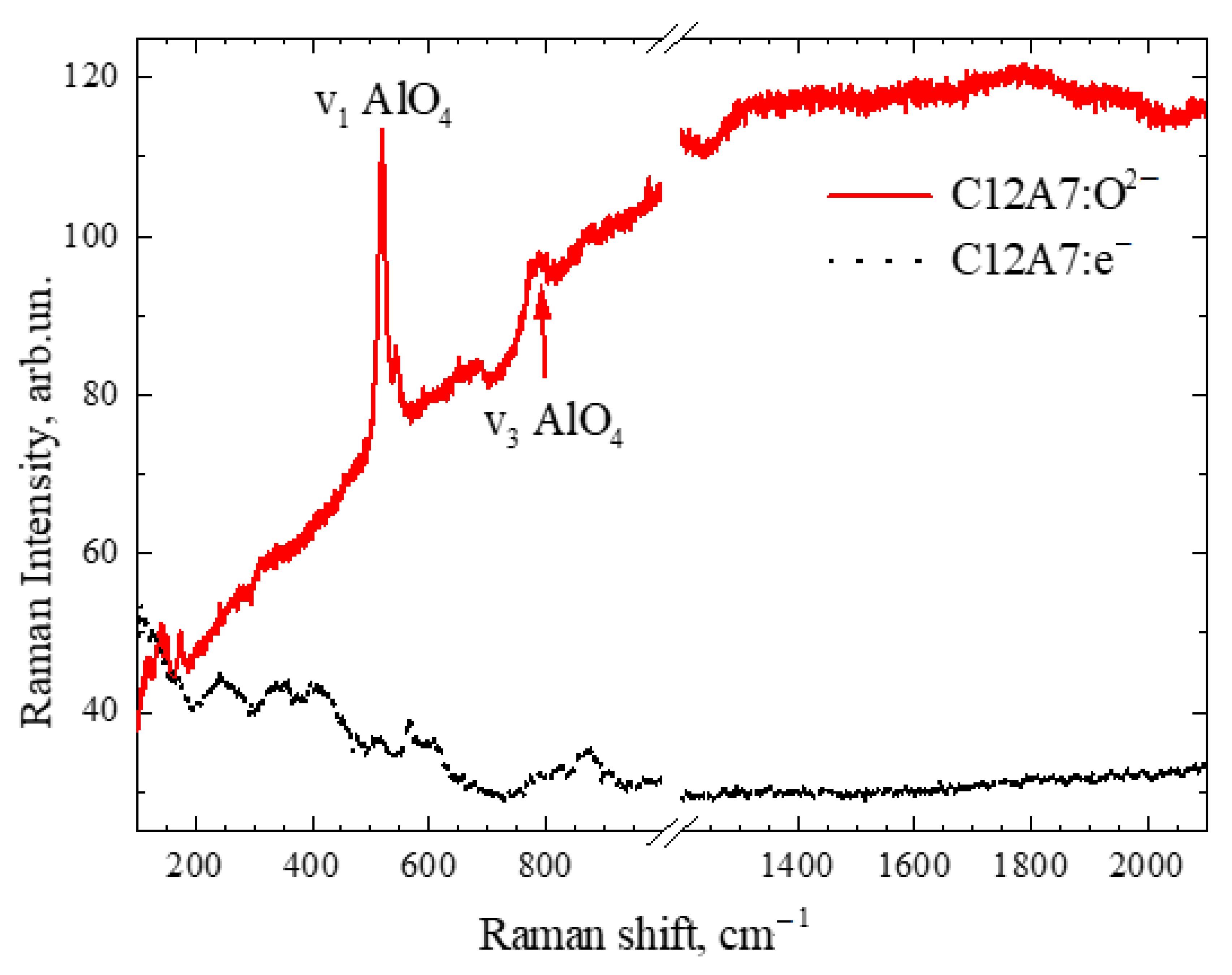
3.3. Raman Studies
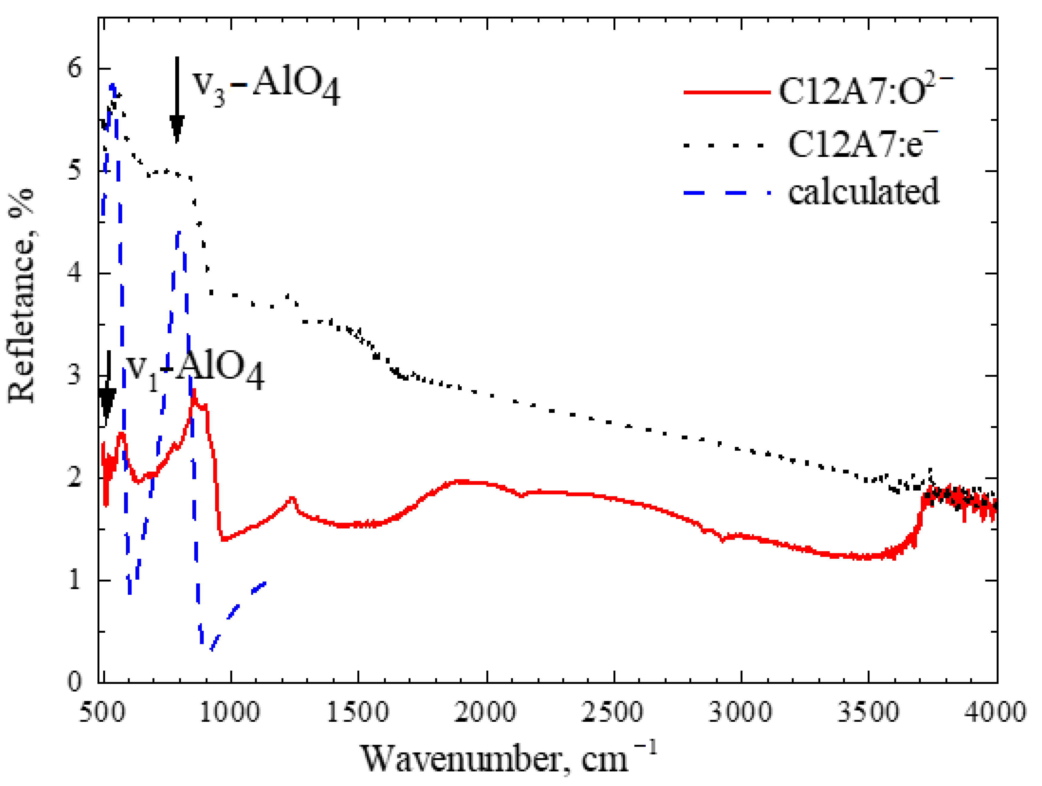
3.4. FTIR Spectroscopy
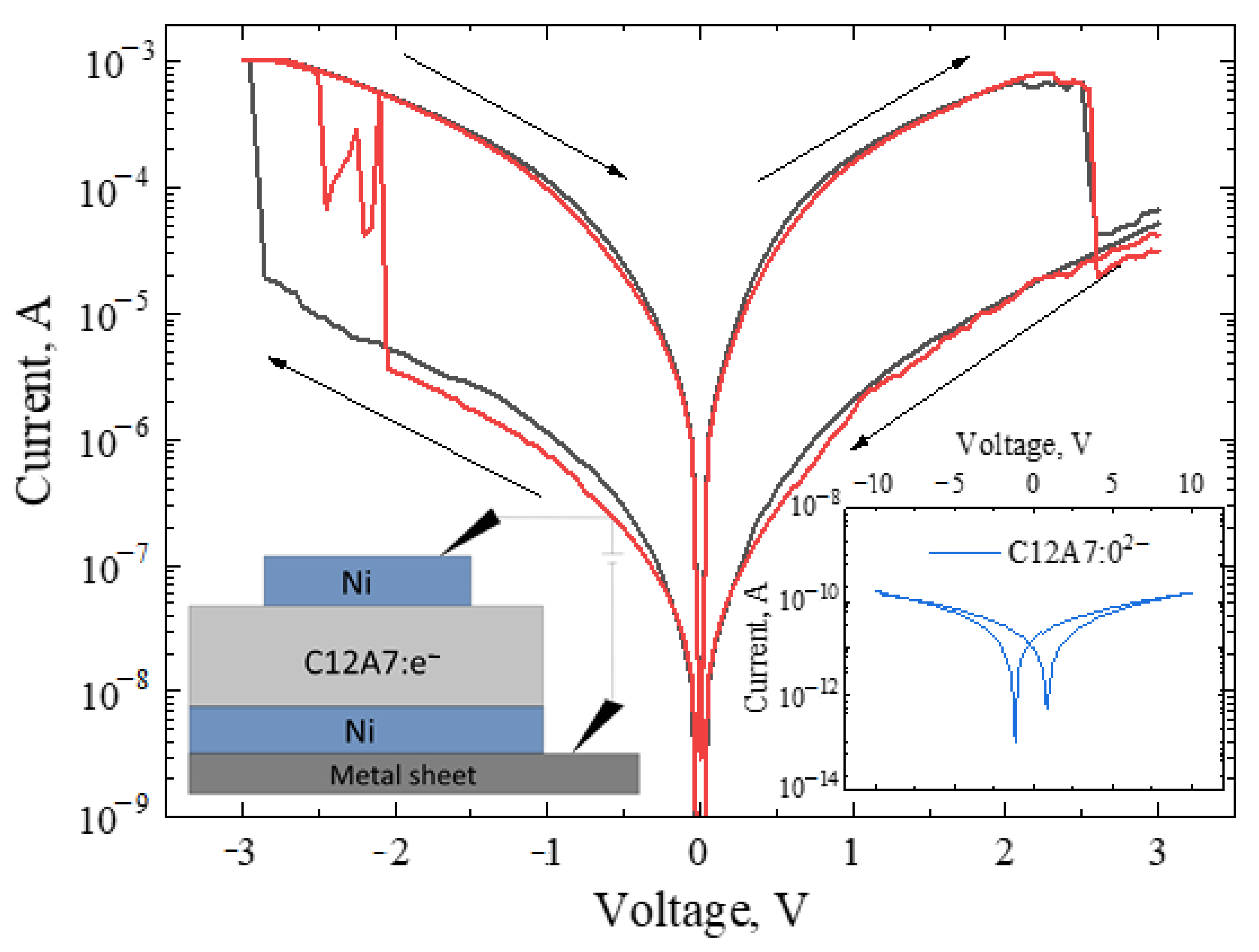
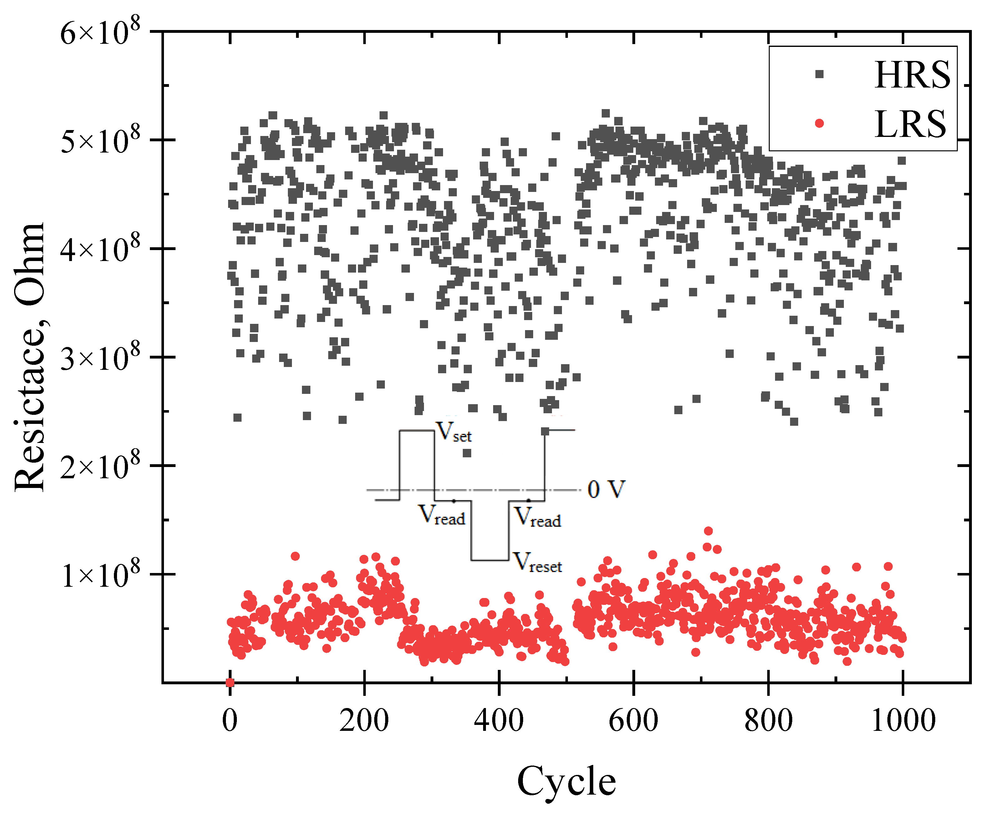
3.5. Electrophysical Studies
4. Conclusions
Author Contributions
Funding
Institutional Review Board Statement
Informed Consent Statement
Data Availability Statement
Acknowledgments
Conflicts of Interest
References
- Pickett, M.D.; Stanley Williams, R. Sub-100fJ and Sub-Nanosecond Thermally Driven Threshold Switching in Niobium Oxide Crosspoint Nanodevices. Nanotechnology 2012, 23, 215202. [Google Scholar] [CrossRef] [PubMed]
- Waser, R.; Aono, M. Nanoionics-Based Resistive Switching Memories. Nat. Mater. 2007, 6, 833–840. [Google Scholar] [CrossRef] [PubMed]
- Sun, W.; Gao, B.; Chi, M.; Xia, Q.; Yang, J.J.; Qian, H.; Wu, H. Understanding Memristive Switching via in Situ Characterization and Device Modeling. Nat. Commun. 2019, 10, 3453. [Google Scholar] [CrossRef] [PubMed]
- Gismatulin, A.A.; Kamaev, G.N.; Kruchinin, V.N.; Gritsenko, V.A.; Orlov, O.M.; Chin, A. Charge Transport Mechanism in the Forming-Free Memristor Based on Silicon Nitride. Sci. Rep. 2021, 11, 2417. [Google Scholar] [CrossRef] [PubMed]
- Ambrogio, S.; Balatti, S.; Cubeta, A.; Calderoni, A.; Ramaswamy, N.; Ielmini, D. Statistical Fluctuations in HfOx Resistive-Switching Memory: Part I-Set/Reset Variability. IEEE Trans. Electron. Devices 2014, 61, 2912–2919. [Google Scholar] [CrossRef]
- Shaposhnikov, A.V.; Perevalov, T.V.; Gritsenko, V.A.; Cheng, C.H.; Chin, A. Mechanism of GeO2 Resistive Switching Based on the Multi-Phonon Assisted Tunneling between Traps. Appl. Phys. Lett. 2012, 100, 243506. [Google Scholar] [CrossRef]
- Yao, J.; Sun, Z.; Zhong, L.; Natelson, D.; Tour, J.M. Resistive Switches and Memories from Silicon Oxide. Nano Lett. 2010, 10, 4105–4110. [Google Scholar] [CrossRef]
- Strukov, D.B.; Snider, G.S.; Stewart, D.R.; Williams, R.S. The Missing Memristor Found. Nature 2008, 453, 80–83. [Google Scholar] [CrossRef]
- Galuskin, E.; Galuskina, I.; Vapnik, Y.; Murashko, M. Molecular Hydrogen in Natural Mayenite. Minerals 2020, 10, 560. [Google Scholar] [CrossRef]
- Hayashi, K.; Hirano, M.; Matsuishi, S.; Hosono, H. Microporous Crystal 12CaO·7Al2O3 Encaging Abundant O- Radicals. J. Am. Chem. Soc. 2002, 124, 738–739. [Google Scholar] [CrossRef]
- Hayashi, K.; Matsuishi, S.; Kamiya, T.; Hirano, M.; Hosono, H. Light-Induced Conversion of an Insulating Refractory Oxide into a Persistent Electronic Conductor. Nature 2002, 419, 462–465. [Google Scholar] [CrossRef]
- Matsuishi, S.; Toda, Y.; Miyakawa, M.; Kamiya, T.; Hirano, M.; Tanaka, I.; Hosono, H. High-Density Electron Anions in a Nanoporous Single Crystal [Ca24Al28O64]4+(4e−). Science 2003, 301, 626–629. [Google Scholar] [CrossRef]
- Rybak, A.A.; Yushkov, I.D.; Nikolaev, N.A.; Kapishnikov, A.V.; Volodin, A.M.; Krivyakin, G.K.; Kamaev, G.N.; Geydt, P.V. Electrophysical Properties of Polycrystalline C12A7:e− Electride. Electronics 2022, 11, 668. [Google Scholar] [CrossRef]
- Adachi, Y.; Kim, S.W.; Kamiya, T.; Hosono, H. Bistable Resistance Switching in Surface-Oxidized C12A7:e− Single-Crystal. Mater. Sci. Eng. B Solid State Mater. Adv. Technol. 2009, 161, 76–79. [Google Scholar] [CrossRef]
- Hosono, H.; Kim, S.W.; Miyakawa, M.; Matsuishi, S.; Kamiya, T. Thin Film and Bulk Fabrication of Room-Temperature-Stable Electride C12A7:e− Utilizing Reduced Amorphous 12CaO 7Al2O3(C12A7). J. Non Cryst. Solids 2008, 354, 2772–2776. [Google Scholar] [CrossRef]
- Miyakawa, M.; Hiramatsu, H.; Kamiya, T.; Hirano, M.; Hosono, H. Fabrication and Electron Transport Properties of Epitaxial Films of Electron-Doped 12CaO·7Al2O3 and 12SrO·7Al2O3. J. Solid State Chem. 2010, 183, 385–391. [Google Scholar] [CrossRef]
- Ilyina, E.V.; Gerus, Y.Y.; Cherepanova, S.V.; Bedilo, A.F. Synthesis of C12A7 Calcium Aluminate Aerogels. Mater. Lett. 2021, 293, 129699. [Google Scholar] [CrossRef]
- Zaikovskii, V.I.; Volodin, A.M.; Stoyanovskii, V.O.; Cherepanova, S.V.; Vedyagin, A.A. Effect of Carbon Coating on Spontaneous C12A7 Whisker Formation. Appl. Surf. Sci. 2018, 444, 336–338. [Google Scholar] [CrossRef]
- Yakovlev, I.V.; Volodin, A.M.; Papulovskiy, E.S.; Andreev, A.S.; Lapina, O.B. Structure of Carbon-Coated C12A7 Electride via Solid-State NMR and DFT Calculations. J. Phys. Chem. C 2017, 121, 22268–22273. [Google Scholar] [CrossRef]
- Kapishnikov, A.V.; Kenzhin, R.M.; Koskin, A.P.; Volodin, A.M.; Geydt, P.V. Mayenite Synthesis from Hydroxide Precursors: Structure Formation and Active Sites on Its Surface. Materials 2022, 15, 778. [Google Scholar] [CrossRef]
- Toby, B.H.; von Dreele, R.B. GSAS-II: The Genesis of a Modern Open-Source All Purpose Crystallography Software Package. J. Appl. Crystallogr. 2013, 46, 544–549. [Google Scholar] [CrossRef]
- Palacios, L.; de La Torre, Á.G.; Bruque, S.; García-Muñoz, J.L.; García-Granda, S.; Sheptyakov, D.; Aranda, M.A.G. Crystal Structures and In-Situ Formation Study of Mayenite Electrides. Inorg. Chem. 2007, 46, 4167–4176. [Google Scholar] [CrossRef]
- Palacios, L.; Cabeza, A.; Bruque, S.; García-Granda, S.; Aranda, M.A.G. Structure and Electrons in Mayenite Electrides. Inorg. Chem. 2008, 47, 2661–2667. [Google Scholar] [CrossRef] [PubMed]
- Kim, S.W.; Miyakawa, M.; Hayashi, K.; Sakai, T.; Hirano, M.; Hosono, H. Simple and Efficient Fabrication of Room Temperature Stable Electride: Melt-Solidification and Glass Ceramics. J. Am. Chem. Soc. 2005, 127, 1370–1371. [Google Scholar] [CrossRef] [PubMed]
- Kim, S.W.; Matsuishi, S.; Miyakawa, M.; Hayashi, K.; Hirano, M.; Hosono, H. Fabrication of Room Temperature-STable 12CaO·7Al2O3 Electride: A Review. J. Mater. Sci. Mater. Electron. 2007, 18, 5–14. [Google Scholar] [CrossRef]
- Li, F.; Zhang, X.; Zhang, J. Aluminothermic Synthesis of [Ca24Al28O64]4+(4e−) Electride Ceramic Directly from Ca3Al2O6 Precursor. Vacuum 2019, 167, 352–356. [Google Scholar] [CrossRef]
- Li, F.; Zhang, X.; Liu, H. Calciothermic Synthesis of Inorganic [Ca24Al28O64]4+(4e−) Electride from Solid-Derived Precursor. Vacuum 2019, 169, 19–21. [Google Scholar] [CrossRef]
- Torréns-Martín, D.; Fernández-Carrasco, L.; Martínez-Ramírez, S. Hydration of Calcium Aluminates and Calcium Sulfoaluminate Studied by Raman Spectroscopy. Cem. Concr. Res. 2013, 47, 43–50. [Google Scholar] [CrossRef]
- Zahedi, M.; Roohpour, N.; Ray, A.K. Kinetic Study of Crystallisation of Sol-Gel Derived Calcia-Alumina Binary Compounds. J. Alloys Compd. 2014, 582, 277–282. [Google Scholar] [CrossRef][Green Version]
- Kim, S.W.; Shimoyama, T.; Hosono, H. Solvated Electrons in High-TemperatureMelts and Glasses of the Room-Temperature Stable Electride [Ca24Al28O64]4+·4e−. Science 2011, 333, 68–71. [Google Scholar] [CrossRef]
- Wang, R.; Yang, H.; Lu, Y.; Kanamori, K.; Nakanishi, K.; Guo, X. Synthesis, Reduction, and Electrical Properties of Macroporous Monolithic Mayenite Electrides with High Porosity. ACS Omega 2017, 2, 8148–8155. [Google Scholar] [CrossRef]
- Sriwong, C.; Phrompet, C.; Tuichai, W.; Karaphun, A.; Kurosaki, K.; Ruttanapun, C. Synthesis, Microstructure, Multifunctional Properties of Mayenite Ca12Al14O33 (C12A7) Cement and Graphene Oxide (GO) Composites. Sci. Rep. 2020, 10, 11077. [Google Scholar] [CrossRef]
- Nishio, Y.; Nomura, K.; Miyakawa, M.; Hayashi, K.; Yanagi, H.; Kamiya, T.; Hirano, M.; Hosono, H. Fabrication and Transport Properties of 12CaO·7Al2O3 (C12A7) Electride Nanowire. Phys. Status Solidi A Appl. Mater. Sci. 2008, 205, 2047–2051. [Google Scholar] [CrossRef]
- Xiao, Y.; Zhang, X.; Zhang, J. Rapid Preparation of [Ca23.04Sr0.96Al28O64]4+(4e−) Electrides Block by Spark Plasma Sintering. J. Alloys Compd. 2021, 872, 159611. [Google Scholar] [CrossRef]
- Hurd, C.M. Quantum Tunnelling and the Temperature Dependent DC Conduction in Low-Conductivity Semiconductors. J. Phys. C Solid State Phys. 1985, 18, 6487–6499. [Google Scholar] [CrossRef]
- Hosono, H.; Hayashi, K.; Kamiya, T.; Atou, T.; Susaki, T. New Functionalities in Abundant Element Oxides: Ubiquitous Element Strategy. Sci. Technol. Adv. Mater. 2011, 12, 034303. [Google Scholar] [CrossRef]


Publisher’s Note: MDPI stays neutral with regard to jurisdictional claims in published maps and institutional affiliations. |
© 2022 by the authors. Licensee MDPI, Basel, Switzerland. This article is an open access article distributed under the terms and conditions of the Creative Commons Attribution (CC BY) license (https://creativecommons.org/licenses/by/4.0/).
Share and Cite
Yushkov, I.D.; Kamaev, G.N.; Volodin, V.A.; Geydt, P.V.; Kapishnikov, A.V.; Volodin, A.M. Resistance Switching in Polycrystalline C12A7 Electride. Micromachines 2022, 13, 1917. https://doi.org/10.3390/mi13111917
Yushkov ID, Kamaev GN, Volodin VA, Geydt PV, Kapishnikov AV, Volodin AM. Resistance Switching in Polycrystalline C12A7 Electride. Micromachines. 2022; 13(11):1917. https://doi.org/10.3390/mi13111917
Chicago/Turabian StyleYushkov, Ivan D., Gennadiy N. Kamaev, Vladimir A. Volodin, Pavel V. Geydt, Aleksandr V. Kapishnikov, and Alexander M. Volodin. 2022. "Resistance Switching in Polycrystalline C12A7 Electride" Micromachines 13, no. 11: 1917. https://doi.org/10.3390/mi13111917
APA StyleYushkov, I. D., Kamaev, G. N., Volodin, V. A., Geydt, P. V., Kapishnikov, A. V., & Volodin, A. M. (2022). Resistance Switching in Polycrystalline C12A7 Electride. Micromachines, 13(11), 1917. https://doi.org/10.3390/mi13111917