Featured Application
The proposed dual-band MIMO antenna can be a good candidate for 5G and 4G applications.
Abstract
In this paper, a compact planar dual-band multiple-input and multiple-output (MIMO) antenna with high isolation is presented to satisfy the increasing requirements of wireless communication. The proposed antenna array consists of two identical radiating elements which are fed through micro-strip lines. A rectangular micro-strip stub with defected ground plane is employed to achieve a high isolation which is less than −15 dB between the two antenna elements. The size of the entire MIMO antenna is 32 × 32 × 1.59 mm3, which is printed on an FR4 substrate. The proposed MIMO antenna is optimized to operate in 2.36–2.59 GHz and 3.17–3.77 GHz bands, which can cover the fifth-generation (5G) n7 (2.5–2.57 GHz) and the fourth-generation (4G) Long Term Evolution (LTE) band 42 (3.4–3.6 GHz). The proposed MIMO antenna is feasible for the 5G and 4G applications.
1. Introduction
With the coming of the 5G era, it is of the utmost importance to greatly improve large-capacity data transmission and link reliability of wireless communication systems. To meet the requirements, MIMO antennas have been widely applied in wireless communication systems. However, there are many challenges in the design of MIMO antennas with compact size, high gain, and high isolation characteristics.
In recent years, various MIMO techniques for decoupling and miniaturization have been presented [1,2,3,4,5]. A tapered slot in the ground plane of a MIMO antenna provides both high isolation at microwave band and high gain at millimeter-wave band [1]. In [2], a closely coupled dual-band MIMO patch antenna with H-shaped defect ground structures achieves 34.2 dB isolation at 3.7 GHz and 36.3 dB isolation at 4.1 GHz. A novel balanced open-slot antenna as an eight-antenna MIMO array antenna element is proposed [3]. The eight-antenna array can achieve high isolation (>17.5 dB) and high total efficiency (>60%) simultaneously. A defected ground structure (DGS) and electromagnetic bandgap (EBG) are employed to reduce the mutual coupling, and the presented antenna can realize an ECC lower than 0.002 [4]. By placing a split EBG structure between two meander-line antennas, the mutual coupling can be significantly reduced [5].
Additionally, to cover as many wireless communication standards as possible, MIMO antennas with compact size, broadband, and multiband characteristics are preferred [6,7,8,9,10,11,12,13,14,15]. In [16], the presented antenna can operate in the 900 MHz, 1800–1900 MHz, 700 MHz, and 2.45 GHz bands. Similarly, in [17], a multiband and dual-element diversity antenna system with an overall size of 105 × 55 × 1.5 mm3 can cover an exceptionally broad bandwidth, from 890 MHz to 6 GHz. In addition, a wideband printed dual-antenna [18] with three neutralization lines can cover the GSM1800, GSM1900, UMTS, LTE2300, LTE2500, and 2.4-GHz WLAN bands. There are many MIMO antennas that can cover 5G spectrum [19,20,21]. In [22], an eight element MIMO antenna system is proposed for sub-6 GHz 5G mobile terminals. The proposed antenna array in [23] consists of an L-shaped feeding strip, a parasitic rectangle strip, and a modified Z-shaped radiating strip, which operates on the 3.5 GHz band (3.4–3.6 GHz) and 5 GHz band (4.8–5 GHz) for the applications of 5G. A multi-band MIMO antenna is designed to meet the requirements of the 4G and 5G mobile terminals with essential bandwidth for higher data rate applications [24].
In this paper, the proposed MIMO antenna has two identical antenna elements which are perpendicular to each other and a rectangular micro-strip stub is connected to the defected ground plane. The measured results show that the presented antenna can cover both 4G (3.4–3.6 GHz) and 5G (2.5–2.57 GHz) spectrums. The isolation is less than −15 dB in the desired frequency bands. The overall size of the presented compact planar dual-band MIMO antenna is 32 × 32 × 1.59 mm3.
2. Antenna Geometry and Design Consideration
The geometry of the proposed dual-band MIMO antenna is shown in Figure 1. The proposed antenna structure consists of two identical radiating elements which are fed through micro-strip lines. The antenna is fabricated on an FR4 substrate with relative permittivity εr of 4.4, loss tanδ of 0.02, and thickness of 1.59 mm. A photograph of the manufactured antenna is shown in Figure 2.
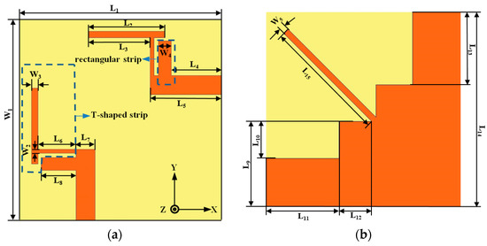
Figure 1.
Configuration of the proposed antenna (a) top view; (b) bottom view.
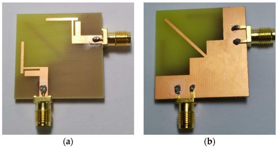
Figure 2.
Photograph of the fabricated antenna prototype (a) top view; (b) bottom view.
The two identical antenna elements are printed on two adjacent sides of the substrate. The radiating element is composed of a T-shaped strip and a rectangular strip. The upper half of the T-shaped strip, the lower half of the T-shaped strip, and the rectangular strip mainly realize impedance matching of the lower and higher frequency bands.
To investigate the influence of the critical parameters of the proposed antenna, a parametric study has been carried out by changing the values of antenna dimensions. The current density distributions of the presented antenna in different frequency bands are shown in Figure 3. When the antenna operates at 2.475 GHz, the current distributions mainly appear on the upper half of the T-shaped strip and the whole rectangular strip on the bottom side as shown in Figure 3a. When the antenna operates at 3.47 GHz, the current distributions mainly appear on the lower half of the T-shaped strip and the edge of the rectangular strip on the top side of the substrate. The current only concentrates on the top part of the stub on the bottom side of the substrate, as shown in Figure 3b. Therefore, we can adjust the dimension of the T-shaped strip to optimize the current distributions which can be used to tune both resonance frequencies and isolation.
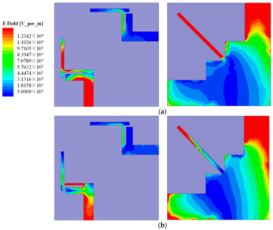
Figure 3.
Surface current distributions at (a) 2.475 GHz; (b) 3.47 GHz.
Figure 4 illustrates the reflection coefficients of the presented antenna with different values of W3 and W2, respectively. In Figure 4a, when the value of W2 is 0.5 mm, with the width of W3 increasing, the low-frequency mode shifts to the lower frequencies. In Figure 4b, when the value of W3 is 1 mm, with the width of W2 decreasing, the high-frequency mode shifts to the lower frequencies. In Figure 4c, when the value of W3 is 1 mm and W2 is 0.5 mm, with the width of L4 increasing, the high-frequency mode shifts to the lower frequencies. The optimum values of W3, W2, and L4 are 1 mm, 0.5 mm and 0.8 mm, respectively. The final dimensions of the proposed antenna are listed in Table 1.
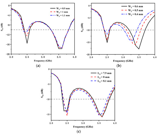
Figure 4.
Simulated reflection coefficients for different values of (a) W3; (b) W2; (c) L4.

Table 1.
Dimensions of the proposed antenna (unit: mm).
3. Results and Discussion
Figure 5 shows the simulated and measured reflection coefficients. There was a little error between the measurement results and the simulation results, which could be due to many different reasons. From the measurement results, we can see that the bandwidth with reflection coefficient less than −10 dB was 230 MHz (2.36–2.59 GHz) and 600 MHz (3.17–3.77 GHz). The realized two frequency bands can cover 5G n7 (2.5–2.57 GHz) and 4G 42 (3.4–3.6 GHz). Figure 6 shows the simulated and measured S21. The measured mutual coupling between the two antenna elements was less than −15 dB in the desired frequency bands. Some discrepancy between the simulated and measured results should be mainly owing to fabrication tolerance, the uncertainties of dielectric constant and loss tangent of the substrate material, and SMA connector hand soldering. Furthermore, the fabrication error may have evoked another surface current path which changed the isolation.
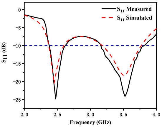
Figure 5.
Simulated and measured S11 of the proposed antenna.

Figure 6.
Simulated and measured S21 of the proposed antenna.
Figure 7 shows the normalized measured antenna radiation patterns at 2.475 GHz and 3.47 GHz. Since the proposed antenna structure is symmetrical, one port was fixed and the other port was connected to a 50 Ω load during measurement. The solid and dash lines represent the co-polarization and cross-polarization, respectively. The measured antenna peak gain and total efficiency are presented in Figure 8. Since the radiation efficiency of an antenna is proportional to the dimension of antenna, the radiation efficiency of the lower frequency band is higher than that of the higher frequency band. The measured results show that the proposed antenna had a peak gain of 5.8 dBi at 2.36–2.59 GHz and 5.9 dBi at 3.17–3.77 GHz, and the proposed antenna had high efficiency of 80% at 2.36–2.59 GHz and 76% at 3.17–3.77 GHz. The envelope correlation coefficient (ECC) is an important indicator to judge the performance of a MIMO communication system. Figure 9 shows the simulated ECC of the MIMO antenna. The ECC was less than 0.02 over the operating band, which is acceptable for MIMO applications. A comparison of the proposed antenna with other referenced antennas is provided in Table 2. In this table, it can be observed that the achieved peak gain of the proposed antenna was higher than that of the designs demonstrated in [11,12,15]. Additionally, the size of the proposed antenna is more compact compared to other referenced antennas.
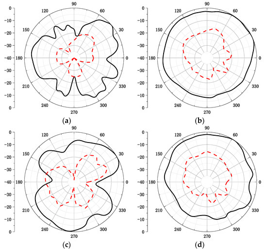
Figure 7.
Measured radiation patterns of the proposed antenna (a) 2.475 GHz E-plane; (b) 2.475 GHz H-plane; (c) 3.47 GHz E-plane; and (d) 3.47 GHz H-plane.
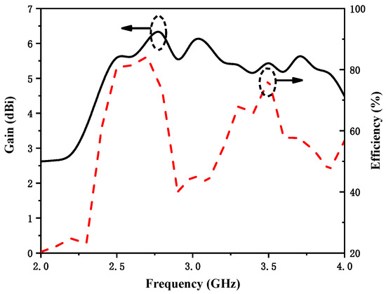
Figure 8.
Measured antenna peak gain and total efficiency.

Figure 9.
Simulated envelope correlation coefficient (ECC) of the multiple-input and multiple-output (MIMO) antenna.
Table 2.
Comparison of the proposed antenna with other referenced antennas.
4. Conclusions
In this paper, a planar dual-band MIMO antenna with high isolation is presented. The two identical antenna elements were printed on two adjacent sides of the substrate. The radiating element was composed of a T-shaped strip and a rectangular strip. The proposed MIMO antenna was optimized to operate in the 2.475 GHz (2.36–2.59 GHz) and 3.47 GHz (3.17–3.77 GHz) bands, which can cover 5G n7 (2.5–2.57 GHz) and 4G LTE band 42 (3.4–3.6 GHz). The proposed antenna had a peak gain of 5.8 dBi at 2.36–2.59 GHz and 5.9 dBi at 3.17–3.77 GHz. The measured efficiency of the proposed antenna was 80% at 2.36–2.59 GHz and 76% at 3.17–3.77 GHz, respectively. The simulated ECC was less than 0.02. The proposed dual-band MIMO antenna is a good candidate for 4G and 5G applications.
Author Contributions
Conceptualization, R.Y.; methodology, Z.C.; data curation, S.X.; investigation, Q.C.; writing—original draft preparation, R.Y.; writing—review and editing, X.W.; G.L.; supervision and funding acquisition, G.L. All authors have read and agreed to the published version of the manuscript.
Funding
This work was funded in part by the National Natural Science Foundation of China under Grant No. 61671330, the Science and Technology Department of Zhejiang Province under Grant No. LGG19F010009, and Wenzhou Municipal Science and Technology Program under Grant No. C20170005 and No. 2018ZG019.
Institutional Review Board Statement
Not applicable.
Informed Consent Statement
Not applicable.
Data Availability Statement
Data is contained within the article.
Conflicts of Interest
The authors declare no conflict of interest.
References
- Ikram, M.; Nguyen-Trong, N.; Abbosh, A.M. Realization of a Tapered Slot Array as both Decoupling and Radiating Structure for 4G/5G Wireless Devices. IEEE Access 2019, 7, 159112–159118. [Google Scholar] [CrossRef]
- Niu, Z.; Zhang, H.; Chen, Q.; Zhong, T. Isolation Enhancement in Closely Coupled Dual-Band MIMO Patch Antennas. IEEE Antennas Wirel. Propag. Lett. 2019, 18, 1686–1690. [Google Scholar] [CrossRef]
- Li, Y.; Sim, C.; Luo, Y.; Yang, G. High-Isolation 3.5 GHz Eight-Antenna MIMO Array Using Balanced Open-Slot Antenna Element for 5G Smartphones. IEEE Trans. Antennas Propag. 2019, 67, 3820–3830. [Google Scholar] [CrossRef]
- Liu, Y.; Yang, X.; Jia, Y. A Low Correlation and Mutual Coupling MIMO Antenna. IEEE Access 2019, 7, 127384–127392. [Google Scholar] [CrossRef]
- Tan, X.; Wang, W.; Wu, Y.; Liu, Y.; Kishk, A.A. Enhancing Isolation in Dual-Band Meander-Line Multiple Antenna by Employing Split EBG Structure. IEEE Trans. Antennas Propag. 2019, 67, 2769–2774. [Google Scholar] [CrossRef]
- Zhang, S.; Pedersen, G.F. Mutual Coupling Reduction for UWB MIMO Antennas with a Wideband Neutralization Line. IEEE Antennas Wirel. Propag. Lett. 2016, 15, 166–169. [Google Scholar] [CrossRef]
- Shang, W.; Du, Z. Decoupled Dual-Antenna System Using Crossed Neutralization Lines for LTE/WWAN Smartphone Applications. IEEE Antennas Wirel. Propag. Lett. 2015, 14, 523–526. [Google Scholar] [CrossRef]
- Su, S.; Lee, C.; Chang, F. Printed MIMO-Antenna System Using Neutralization-Line Technique for Wireless USB-Dongle Applications. IEEE Trans. Antennas Propag. 2012, 60, 456–463. [Google Scholar] [CrossRef]
- Xu, Z.; Deng, C. High-Isolated MIMO Antenna Design Based on Pattern Diversity for 5G Mobile Terminals. IEEE Antennas Wirel. Propag. Lett. 2020, 19, 467–471. [Google Scholar] [CrossRef]
- Jehangir, S.S.; Sharawi, M.S. A Miniaturized UWB Bi-planar Yagi-Like MIMO Antenna System. IEEE Antennas Wirel. Propag. Lett. 2017, 16, 2320–2323. [Google Scholar] [CrossRef]
- Jehangir, S.S.; Sharawi, M.S. A Single Layer Semi-Ring Slot Yagi-Like MIMO Antenna System with High Front-to-Back Ratio. IEEE Trans. Antennas Propag. 2017, 65, 937–942. [Google Scholar] [CrossRef]
- Li, Q.L.; Cheung, S.W.; Wu, D.; Yuk, T.I. Optically Transparent Dual-Band MIMO Antenna Using Micro-Metal Mesh Conductive Film for WLAN System. IEEE Antennas Wirel. Propag. Lett. 2017, 16, 920–923. [Google Scholar] [CrossRef]
- Dou, Y.; Dong, G.; Lin, J.; Cai, Q.; Liu, G. A Low Profile Dual-Band High Gain Directional Antenna for Anti-Interference WLAN Station Applications. Appl. Sci. 2021, 11, 2007. [Google Scholar] [CrossRef]
- Lu, D.; Wang, L.; Yang, E.; Wang, G. Design of High-Isolation Wideband Dual-Polarized Compact MIMO Antennas with Multiobjective Optimization. IEEE Trans. Antennas Propag. 2018, 66, 1522–1527. [Google Scholar] [CrossRef]
- Bai, J.; Zhi, R.; Wu, W.; Shangguan, M.; Wei, B.; Liu, G. A Novel Multiband MIMO Antenna for TD-LTE and WLAN Applications. Prog. Electromagn. Res. Lett. 2018, 74, 131–136. [Google Scholar] [CrossRef]
- Shoaib, S.; Shoaib, I.; Shoaib, N.; Chen, X.; Parini, C. Compact and Printed MIMO Antennas for 2G/3G and 4G-LTE Mobile Tablets. In Proceedings of the IEEE-APS Topical Conference on Antennas and Propagation in Wireless Communications (APWC), Turin, Italy, 7–11 September 2015; pp. 674–677. [Google Scholar]
- Rao, Q.; Wilson, K. Design, Modeling, and Evaluation of a Multiband MIMO/Diversity Antenna System for Small Wireless Mobile Terminals. IEEE Trans. Compon. Packag. Manuf. Technol. 2011, 3, 410–419. [Google Scholar] [CrossRef]
- Wang, Y.; Du, Z. A Wideband Printed Dual-Antenna with Three Neutralization Lines for Mobile Terminals. IEEE Trans. Antennas Propag. 2014, 62, 1495–1500. [Google Scholar] [CrossRef]
- Trinh, L.H.; Lizzi, L.; Staraj, R.; Ribero, J.M. Reconfigurable Antenna for Future Spectrum Reallocations in 5G Communications. IEEE Antennas Wirel. Propag. Lett. 2015, 15, 1297–1300. [Google Scholar] [CrossRef]
- Ban, Y.L.; Li, C.; Wu, G.; Wong, K.L. 4G/5G Multiple Antennas for Future Multi-Mode Smartphone Applications. IEEE Access 2016, 4, 2981–2988. [Google Scholar] [CrossRef]
- Chen, Q.; Lin, H.; Wang, J.; Ge, L.; Li, Y.; Pei, T. Single Ring Slot-Based Antennas for Metal-Rimmed 4G/5G Smartphones. IEEE Trans. Antennas Propag. 2019, 67, 1476–1487. [Google Scholar] [CrossRef]
- Kiani, S.H.; Altaf, A.; Abdullah, M.; Muhammad, F.; Blaauskas, T. Eight Element Side Edged Framed MIMO Antenna Array for Future 5G Smart Phones. Micromachines 2020, 11, 956. [Google Scholar] [CrossRef] [PubMed]
- Huang, J.; Dong, G.; Cai, J.; Li, H.; Liu, G. A Quad-Port Dual-Band MIMO Antenna Array for 5G Smartphone Applications. Electronics 2021, 10, 542. [Google Scholar] [CrossRef]
- Parchin, N.O.; Basherlou, H.J.; Al-Yasir, Y.I.A.; Ullah, A.; Noras, J.M. Multi-Band MIMO Antenna Design with User-Impact Investigation for 4G and 5G Mobile Terminals. Sensors 2019, 19, 456. [Google Scholar] [CrossRef] [PubMed]
Publisher’s Note: MDPI stays neutral with regard to jurisdictional claims in published maps and institutional affiliations. |
© 2021 by the authors. Licensee MDPI, Basel, Switzerland. This article is an open access article distributed under the terms and conditions of the Creative Commons Attribution (CC BY) license (https://creativecommons.org/licenses/by/4.0/).