Abstract
There are two widely recognized global fields in nature: the gravity field and the geomagnetic field. Universal gravitation and Earth rotation are important sources of the Earth’s gravity and geomagnetic fields, which are well known to us. After years of long-term observation, global research, and analysis, it was discovered that we have neglected a direct incident energy of the universe on the Earth. Solar radiation, leading to energy exchange from the atmosphere 100 km above the land surface, is the energy source of the Earth. Polarization is one of the four basic physical properties of solar radiation. After the solar radiation reaches the surface of these media, it reflects, scatters or refracts, and exhibits different degrees of polarization. The polarized solar light forms the Earth–sky polarization vector field. The polarized light dispersion is expected to become a new method for global analysis of the human environment. Polarization detection is the best way to accurately explore the atmospheric effects. Local polarized skylight distribution was found in different sites in the world; however, the global distribution of the polarized sunlight radiation has never been explored. In this paper, we investigate the Global Skylight Polarization Field. This study aimed at providing new insight into the laws of polarization over our Earth. We use a Rayleigh scattering model to obtain the simulation results of the sky polarization field. Rayleigh scattering occurs when the particle size is much smaller than the wavelength of the incident electromagnetic wave. We also use a polarized fisheye camera to collect the sky polarization image and calculate the distribution pattern of the DOLP (degree of linear polarization) and AOLP (azimuth of linear polarization) of the skylight. The stability and gradual change in the degree of polarization in the zenith direction are verified, and the distribution law and daily change law of the degree of polarization in the sky are obtained. With the increase in the solar altitude angle, the degree of polarization will decrease. We also observed the skylight polarization in different weather conditions. Our results demonstrate the physical basis, characteristics, and usability of the polarization field. They show an inevitable trend from optical remote sensing to polarization remote sensing.
1. Introduction
The atmosphere is an important environmental element for human beings, and it is an indispensable natural resource. The Earth’s radiation balance is determined by the combination of aerosols, clouds, atmospheric gases, and surface reflections in the atmosphere [1,2]. When the solar radiation passes through the atmosphere, it is scattered by the atmospheric particles, which will cause the polarization of light. In general, the primary scattering of atmospheric particles causes the sky polarization to produce a positive value, while the multiple scattering causes the sky polarization to produce a negative value. The intersection of positive and negative polarizations in the sky is the atmospheric neutral point (Neutral Point), which is the point of zero polarization in the sky [3]. Due to the scattering absorption of incident sunlight by air molecules and aerosol particles, the sky has a relatively stable polarization mode at some points in the day and at a certain position, which is the sky polarization field [4,5]. In 1809, for the first time, Arago discovered the polarization phenomenon of skylight and found that there is a point in the sky where the degree of polarization is zero, that is, the atmospheric neutral point. In 1870, Strutt proposed the Rayleigh scattering theory, which scientifically explained the polarization phenomenon of sky-scattered light and can more accurately describe the polarization state distribution of scattered light in clear sky.
The human eye cannot directly perceive the polarization information of light, but we can create some fast and high-precision polarization measuring instruments [6], which is one of the hot topics for innovation. Since polarization is one of the basic properties of light, which contains characteristic information of the object being tested, polarization detection is a basic measurement method that cannot be ignored in the field of optical measurement. G. Horváth et al. proved that the skylight polarization field under cloudy, foggy, and dusty weather is similar to that in sunny weather [7,8]. Nathan J. Pust and Joseph A. Shaw [9] proved that the degree of polarization of cloudy weather is significantly lower than that of sunny weather due to the influence of multiple scattering, but the distribution of polarization in azimuth is almost unchanged. A fully automatic imaging, whole-sky, polarized-light-testing instrument is designed and manufactured. The actual distribution of sky polarization mode in cloudy weather is simulated, and the simulation results are consistent with the test results [7]. With the continuous development of polarization instruments, polarization measurement is playing an increasingly important role in many fields [10,11].
When solar radiation enters the Earth–atmosphere system, it is affected by the reflection, scattering, and transmission of atmospheric particles, underlying surface, etc., which cause the polarization of the incoming neutral sunlight [12]. Relevant research found that polarized light is broadly utilized. For example, creatures such as bats use visual polarized light for accurate environmental sensing and navigation [13], voyagers use polarized light to identify directions in the Atlantic Ocean [14], weakly polarized reflected light of the moon can reflect vegetation traces [15], surface-polarized reflections can improve the accuracy of biochemical content inversion [16], and ground-based polarization observations can obtain effective information on solar flares [17]. These cases raise fundamental questions. Is there a skylight polarization field in nature? Can this field penetrate the atmosphere and support surface observations? Is it possible to accurately monitor the interaction between the atmosphere, ocean transpiration, and the surface ecosystem? Can this field be combined with the magnetic field and the gravity field to reach a better understanding of the natural phenomena and laws of the Earth? Solving these problems could lead people to a deeper and wider insight into what skylight polarization can do. For example, the skylight polarization field might be helpful for navigation under complicated natural conditions where signals from global positioning satellites are missing. Moreover, applied to atmospheric or public health-related issues, the polarization field is meaningful to the separation of different kinds of atmospheric particles, or even the μm-size virus existing in the aerosol particles, which polarizes light differently from other particles.
In this study, we explored the laws, characteristics, and global distribution of the skylight polarization field map and its seasonal fluctuation, we explored the stability and continuous diffusivity of the light intensity distributions through coupling land surface and atmosphere polarization effects, we studied the daily periodicity of the skylight polarization field through all-day measurements with polarization instruments, and we also compared the characteristic parameters of the skylight polarization field with the existing gravity field and geomagnetic field. Furthermore, this work provides the possibility to study the three basic vector fields under the influence of the three elements of the vast universe (universal gravitation, Earth rotation, and solar radiation) on the Earth, as well as the scientific understanding of the influence of the three vector fields on all the objects on the Earth.
2. Materials and Methods
The experiment was carried out at the Huairou Solar Observing Station National Astronomical Observatories CAS, Huairou District, Beijing, China. The observing instruments are a Solar Observing Telescope and Nikon D200 digital camera with a fisheye lens and an optical polarizer (Figure 1). We used the digital compass and leveling instruments to find the north direction and adjust the tripod platform to the horizontal position. We then installed the digital camera on the tripod, installed the fisheye lens on the digital camera, and installed the optical polarizer on the top of the fisheye lens. By using the scale around the polarizer, the rotation angle of the polarizer can be obtained, which can be marked as 0 degrees, 60 degrees, and 120 degrees. For each acquisition, the polarizer was rotated at three different degrees, respectively, and three all-sky images with different polarizing angles at that time were obtained. Every 10 min or 30 min, we collected experimental data of the whole sky and observed the distribution of sky-polarized light.
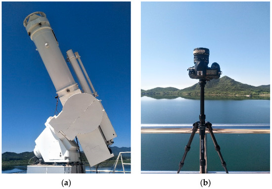
Figure 1.
Telescope (a) and fisheye camera (b) for polarization observation.
Rayleigh scattering and Mie scattering occur in the atmosphere under clear-sky conditions, and the two are also the origin of the atmospheric polarization effects. Thus, they become the theoretical and application basis of the skylight polarization field. The degree of linear polarization (DOLP) is the most important parameter for characterizing polarized light and establishing a polarization model. The DOLP of atmosphere during Rayleigh scattering can be directly simulated by the scattering angle (the angle between the directions of incidence for sunlight and scattering).
In measuring the atmospheric polarization, a Stokes vector, S, is usually used to describe the polarization state of the polarized beam. The Stokes vector, , can be expressed as another form, , where I is the total intensity of light, Q and U are linearly polarized light in two orthogonal directions, and V is circularly polarized light. In atmospheric polarization measurement, circular polarized light, V, is usually ignored because linear polarized light is the most common type of polarization in nature. The Stokes vector represents the polarization state of the light, while the Mueller matrix represents the process of the polarization device changing the Stokes vector of the incident light. If the Stokes vector of the incident light is S and the Mueller matrix of the linear polarization device is T, then the Stokes vector of the outgoing light, , can be obtained by linear transformation, :
The Mueller matrix of the ideal optical detection system is as follows:
where α is the angle between the preferred transmission plane and the reference plane of the linear polarizer.
In the new Stokes vector, S′, the first row is used to represent the intensity of the outgoing light passing through the optical system. If I′ is expressed as a function of α, the intensity of the outgoing light is as follows:
According to Formulas (2) and (3), if the light intensity values at three different α positions are known, then the parameters of the Stokes vector, DOLP, and AOLP can be calculated.
In atmosphere polarized observation, the direction of space-borne observations is from top to bottom, whereas that of ground observations is from bottom to top. However, the DOLP, at a fixed location, ideally does not vary with the observing direction. At a specific moment, the solar altitude and azimuth angles are different at different positions on the Earth. The solar altitude angle is complementary to the zenith angle. In a horizontal coordinate system, the solar altitude angle is the angle between the solar incidence and the normal placement of the observation point, which can be calculated. From this, the solar altitude angles for various positions on Earth can be obtained at the same time so as to obtain the DOLP globally at the nadir directions.
Solar radiation is non-polarized before it enters the atmosphere. In the process of sunlight incidence on the Earth surface, through the scattering interaction with the atmospheric components (gas, aerosol particles, water droplets, and ice crystals), the skylight forms a sky polarization field with the sun as the center. The whole skylight polarization field consists of two elements: the field axis and the force line. The point with the lowest degree of polarization formed by the solar incidence point is the polarization neutral point, which is defined as the axis; the point with this as the center forms a trend of diffusion to the surrounding space (a concentric circle), which is defined as the force line. Thus, the skylight polarization field is formed. Under the condition of a non-equilibrium atmosphere, the force line of the skylight polarization field is distorted, which can be used to measure the distribution of various components in the atmosphere and the properties of the underlying surface. Using the Rayleigh model to represent the scattering of molecules in the atmosphere, we can describe and simulate the state of polarized light and the distribution characteristics of the global skylight polarization field.
The degree of polarization of the atmosphere in Rayleigh scattering can be simulated by the scattering angle θ (the angle between the direction of incident light and the direction of scattered light) [18]:
When a polarization observation is carried out, the satellite observation mode is from top to bottom, and the scattering angle , where is the solar zenith angle. When the ground observation mode is from bottom to top, the scattering angle . For a vertical observation, the degree of the polarization is the same whether from top to bottom or from bottom to top.
At the same time, the solar altitude angle and solar azimuth angle are different at all points in the world. The relationship between the solar altitude angle and the zenith angle satisfies . In the horizontal coordinate system, the sun height angle means the angle between the direct sunlight and the plane where the observation point is located:
where ϕ is the latitude of the observer’s location, ω is the hour angle, and δ is the declination angle.
The time angle ω is the angular distance from the equator of the celestial meridional circle of the observation point to the time circle of the sun. It can be calculated as follows:
where T is the true solar time, and the declination δ is the angle between the Earth’s equator and the connecting line between the sun and the Earth’s center:
where n is the day of year.
The true solar time can be calculated as:
where is the longitude of the place to be measured, “+” is applicable to the eastern hemisphere, “−” is applicable to the western hemisphere, and is the longitude of the standard time zone.
The corrected time difference is:
where .
Therefore, the solar altitude angle of all points in the world at the same time can be obtained, and the degree of polarization can be obtained:
The Rayleigh scattering occurs when the diameter of particles in the atmosphere is much smaller than the wavelength. For visible light, the Rayleigh scattering phenomenon is very significant. A horizontal coordinate system is established to simulate the distribution of the DOLP for the upper half of the sky. The simulated result of the DOLP is shown in Figure 2a for Rayleigh scattering. Mie scattering occurs when the diameter of particles in the atmosphere is comparable to the wavelength of radiation. The simulated result of the DOLP is shown in Figure 2b for Mie scattering. The atmospheric model we used is a second simulation of a satellite signal in the solar spectrum-vector (6SV) [19]. The type of aerosol we used is ocean-type aerosol, and the AOD (Aerosol optical Depth) is 0.5. The polarization effect of the real atmosphere is caused by the combined effects of Rayleigh scattering, Mie scattering, and multiple scattering. Figure 2c shows the measured DOLP under clear weather conditions. The white line is the meridian of the sun. The white solid circle is the polarization neutral point.

Figure 2.
Local sky polarization field simulation and observation. It shows the ground-based observation results of skylight polarization. DOLP represents the ratio of polarized light to total light intensity, where its units are dimensionless with a maximum value of 1.0.
3. Results
3.1. Skylight Polarization in Clear Weather
The experimental site was on the top floor of the Huairou Solar Observing Station National Astronomical Observatories CAS. The experiment was from 9:00 a.m. to 16:00 p.m. on 13 March 2019. The sky was clear and the air quality index was excellent. The experimental instruments are Nikon D200 digital camera, fisheye lens, optical polarizer, and photography tripod. The fisheye lens we used is a sigma 8 mm F3.5 EX DG, which has a maximum field angle of 180 degrees. The linear polarizer we used is a GSP-50. The effective working wavelength of the linear polarizer is 400~700 nm, with an extinction ratio greater than 1000:1. The single transmittance of parallel polarized light is more than 80% at 650 nm. Since the lens was upward to the zenith, the top of the image corresponds to the south direction of the geography, with the bottom of the image corresponding to the north direction, the left corresponding to the west direction, and the right corresponding to the east direction, which is slightly different from the ordinary map. We transformed the RGB information of the color image into gray information, and calculated the Stokes components I, Q, U, DOLP, and AOLP according to the formulas.
Figure 3 shows the change in sky polarization information for the whole day. We can see the change rule of Stokes components I, Q, and U. The light intensity I is largest at the solar spot and sharply decreases towards the surroundings. The Q component and U component are all zero at the position of the sun, which is an isolated point, and both components have a symmetrical axis with the minimum value. As shown in the blue strip in the figure, with the movement of the sun, the symmetrical axis rotates against the direction of the sun’s motion, and the minimum value of the symmetrical axis of the two components is nearly perpendicular to each other, especially at 10:00–15:00, because Q and U are the line-polarized light in two orthogonal directions.
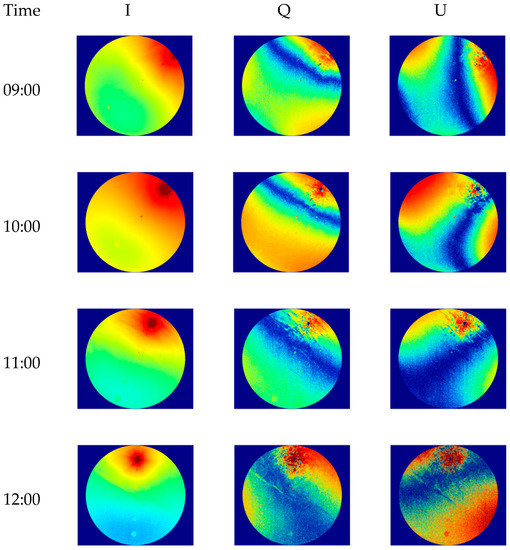
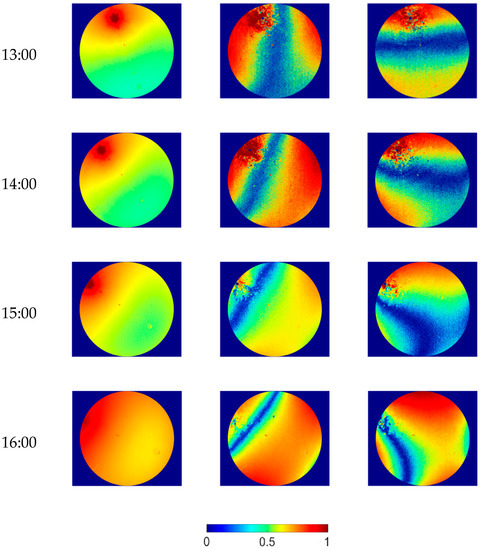
Figure 3.
Daily variation in the Stokes component of skylight (13 March 2019).
Figure 4 shows the simulation results of the DOLP based on the Rayleigh scattering model and the observation results of the DOLP and the AOLP obtained from the experiment. When using a Rayleigh scattering model to simulate the degree of polarization distribution, we calculate the solar altitude and azimuth at each time. A specific geometry between the sun and the detector is formed by the relative positional relationship between each point in the sky and the sun. It is used to calculate the polarization information of each point in the sky. The maximum zenith angle in the Rayleigh model is 60 degrees because the field angle of the fisheye camera is about 120 degrees. For the distribution of the degree of polarization, the simulation results are almost the same as the actual results, because the experimental conditions are ideal, sunny, and the air scattering was mainly Rayleigh scattering. The Rayleigh model can accurately represent the degree of polarization distribution on sunny days, which proves the accuracy of the sun position calculation method and the degree of polarization calculation method. It can be seen from the experimental results that the degree of linear polarization in the whole sky decreases with the increase in the solar altitude angle, and the position of the atmospheric neutral point is related to the position of the sun. The linear degree of polarization presents an obvious circular distribution, which is often called the halo phenomenon.
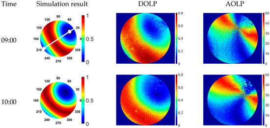
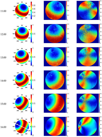
Figure 4.
Daily variation in the DOLP and AOLP of skylight (13 March 2019).
When the solar altitude angle is low, such as at 9:00 a.m. and 16:00 p.m., the two polarization neutral points at the sun point and anti-sun point is more obvious. The degree of polarization of the sun’s incident direction is the smallest, which is the neutral point of the atmosphere. The degree of polarization of the center to the surrounding area gradually increases, and the degree of polarization perpendicular to the sun’s incident direction reaches the maximum and then begins to decrease. This is because there is a neutral point near the sun, and there is also a neutral point on the anti-sun side, that is, the Babinet point and Arago point, respectively. The interaction of the two points results in a double aperture effect.
3.2. Skylight Polarization in Different Weather Conditions
Since the atmospheric particles will affect the scattering of skylight, they can affect the distribution of polarized light in the sky. In order to compare the skylight polarization field in different weather conditions, we used a polarized fisheye camera to take two images on 13 March (sunny day, cloudless) and 2 April (with a small number of clouds) in 2019 (Figure 5).
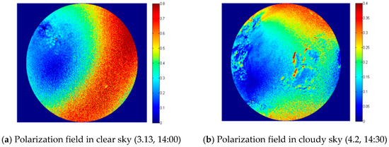
Figure 5.
Skylight polarization in different weather conditions.
We can see that, compared with the clear sky conditions, the presence of clouds reduces the DOLP of the skylight significantly, which is due to the depolarization effect caused by the multiple scattering of the atmosphere due to the presence of clouds. As far as the total light intensity is concerned, the presence of clouds has changed the distribution of the total light intensity in the sky, and the halo centered on the sun has become blurred and interlaced, or has even completely disappeared.
3.3. Defining the Global Skylight Polarization Field
The phenomenon of sky polarization is first found in the ground-based sky observations. Figure 6a shows the observation geometry of the ground-based sky observation, where s represents the sun, OP represents the direction of observation in the sky, and Z represents the zenith. By changing the directions of OP, the polarization distribution of the whole local sky can be observed. The team has made ground observations in Finland, Hungary, Beijing, Zhuhai, and other places in China. These local observations are highly consistent with the model simulation. Nathan J. Pust and Joseph A. Shawhave conducted ground observation in the United States [9], as shown in Figure 6b. The degree of polarization of the atmosphere changes with the position of the sun. Taking the observation point as the origin, when the angle between the observation direction and the sun is 90°, the degree of the polarization reaches the maximum and then gradually reduces to 0° at the mirror point of the incident light. Based on this, we simulated the global atmospheric polarization distribution under the condition of the vertical upward observation of the ground (see the detailed simulation process in the Supplementary Materials), and the results are shown in Figure 6c. The polarization pattern map in the sky is closely related to the solar altitude angle. The degree of polarization varies with the solar altitude angles, and the intensity and direction of the polarized light are different. When the solar altitude angle is low, the polarization intensity ratio in the sky is larger; in other words, the polarization intensity in the sky is larger in the evening or in the morning than at noon. The polarization also varies by season: the spring equinox, summer solstice, autumn equinox, and winter solstice generate regular changes in their distribution.
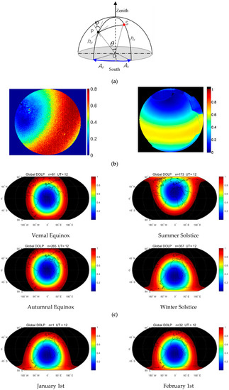
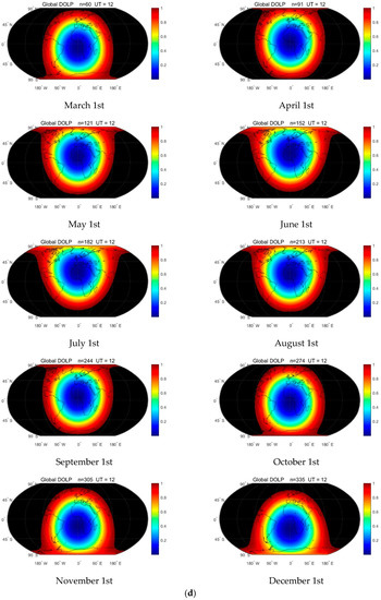
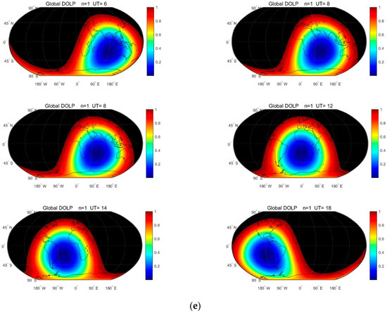
Figure 6.
Theoretical simulation of the global polarization field and verification of a single-point sky polarization: (a) ground observation geometry; (b) actual observation results in different areas; (c) global polarization simulation (upper: spring, summer; lower: autumn, winter); (d) annual variation in the global skylight polarization field (12:00 GMT); (e) diurnal variation in the global skylight polarization field (summer solstice, GMT). (a) Observation geometry and (b) our results in China as well as those obtained by Pust and Shaw in the United States [9].
Figure 6d shows the annual variation in the global skylight polarization field. The theoretical distribution of the global skylight polarization was calculated at 12:00 GMT on the first day of each month. The point with the lowest degree of polarization is theoretically the subsolar point, which moves between the Tropic of Cancer and the Tropic of Capricorn. The cycle of long-term variation is one year. Moreover, Figure 6e shows the diurnal variation in the global skylight polarization field. The theoretical distribution of the global skylight polarization was calculated at six time points on the day of the summer solstice. The point with the lowest degree of polarization changes with the alternation between day and night during a day and with the movement of the sun’s position in the day hemisphere. The cycle of short-period variation is one day.
3.4. Expandability, Stability, and Measurability
Figure 7a is the solar spectral curve measured by the PSR-1100 spectrometer with the polarizer at 0 degrees, 60 degrees, and 120 degrees, respectively. From Figure 7a, it can be seen that the solar radiation is different at different polarizer angles. This reflects that the light intensity distribution is not constant on the cross section of the sunlight propagation direction.
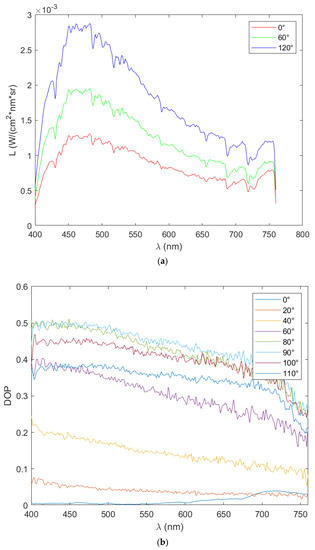
Figure 7.
Measurement of polarization characteristics of the solar spectrum.(a) Solar spectral curve measured by the PSR-1100 spectrometer. (b) Spectral DOLP changing from facing the sun to 90 degrees away from the sun.
Figure 7b is the observation result of the spectral DOLP from the sun to the east at an interval of 5 degrees. It can be seen that the spectral DOLP gradually increases from the minimum value from facing the sun to 90 degrees away from the sun. Furthermore, it increases fastest when it is between 20–80 degrees. It can also be observed that the degree of polarization changes significantly in the range of 400–600 nm. The best wave bands for observation by degree of polarization are 390–455 nm in violet, 455–492 nm in blue, and 492–577 nm in green.
4. Discussion
4.1. The Characteristics of the Neutral Region of the Field
The relationship between the neutral point altitude angle of Babinet and the solar altitude angle is:
where is the solar altitude angle and is the neutral-point altitude angle. The solar altitude angle at the same location and the same day is constantly changing. Therefore, the solar altitude angle of a place is calculated as:
where is the solar altitude angle, is the latitude of the observer’s location, and is the declination angle that can be found in the astronomical almanac, is the hour angle.
In Figure 8, the white area indicates that the DOLP is large, whereas the black area indicates that the DOLP is small. In the polarized image observed, the neutral points (right column) are clearly visible, whether for the nearby Foshan Pavilion at Wanshou Mountain in the Summer Palace (linear distance from the shooting point is about 3.1 km) or the western mountain (linear distance from the shooting point is about 6–8 km). The bare soil (or road) information on the mountain is in strong agreement with the unpolarized image. The polarized information revealed from the images of three different bands of red, green, and blue is also different. In the polarized image of the non-neutral point (left column), the information of the nearby features has a good performance (as seen in the Buddha Xiangge), but the information of the distant mountains is much weaker and is vague. However, only an outline of the mountain appears. This means that the polarized information of distant mountains cannot be effectively obtained when observing through non-neutral points. It also shows that the distance between the observing point and the objects increases, the atmospheric polarization effect increases, and the polarization information of the object decreases. Therefore, the atmospheric effect of non-neutral point observations is stronger than that of neutral point observations. The DOLP images observed through the axis of the polarization field have better contrast when regarding distant objects. The amount of information about the features on the polarization image (right column) observed through the neutral point is much larger than that through the non-neutral point, especially for distant objects.
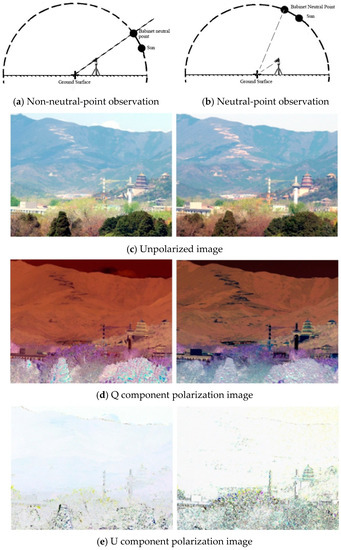
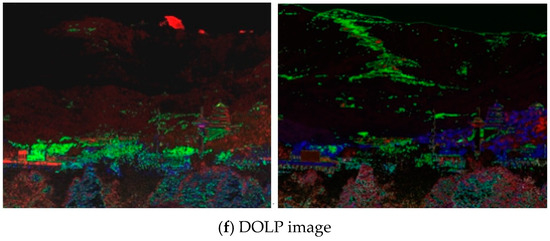
Figure 8.
(a) The observation geometry of the non-field-axis area. (b) The observation geometry of the field-axis area. The imaging device used in the experiment was a polarization spectrum camera. (c) The unpolarized image of the field-axis area and the non-field-axis area has high atmospheric visibility. The image is clear whether it is observed in the neutral-point area or the non-neutral-point area. (d–e) are the Q component and U component images of (c). (f) The DOLP image, which takes (c–e) as the red (R), green (G), and blue (B) bands, respectively.
Figure 9 shows the effect of different BPDF (Bidirectional Polarization Distribution Function) models on TOA (Top of Atmosphere) polarized reflectance under different aerosol optical depth conditions. The first column is the comparison between the simulated and observed surface polarized reflectance. The second column is the comparison between the modeled and the observed TOA polarized reflectance under Rayleigh conditions. The last three columns are the comparison between the modeled and the observed TOA polarized reflectance under different aerosol optical depths ranging from 0.1 to 0.5. The correlation coefficient and RMSE × 100 are displayed in the upper left corner of each sub-figure.
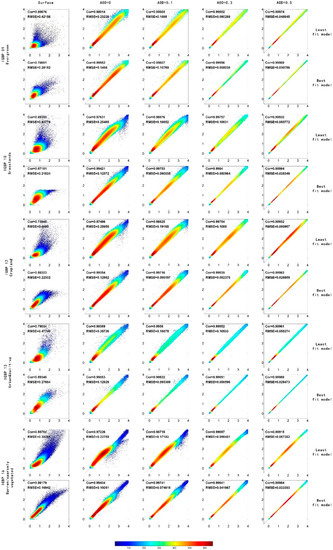
Figure 9.
Effect of different BPDF models on TOA polarized reflectance under different aerosol optical depth conditions.
4.2. The Earth–Skylight Polarization Field
The polarization field of Earth–skylight is the distribution of polarized light formed by solar incident radiation, which is formed by the polarization generated by the incident scattering of solar electromagnetic waves. In the process of atmospheric transmission, sunlight is scattered by air molecules, dust, and aerosols in the atmosphere, which makes the skylight produce polarization. The degree and state of polarization depend on the size, shape, refractive index of particles, the polarization state of incident light, and the angle of observed scattered light. If only the Rayleigh single scattering of light by particles in the air is considered, there is a relatively stable polarization field in the sky at a certain time and position of a day.
The basic field of the Earth–skylight polarization field is the ideal distribution of polarized light formed by solar incident radiation. Its distribution is related to the relationship between the Sun and the Earth, the Earth’s revolution, and the Earth’s rotation. Due to the rotation of the Earth, the basic field of the light polarization field in the Earth’s sky has a diurnal variation with a period of one day. Since the Earth revolves around the Sun, the basic field of the light polarization field in the Earth’s sky has an annual variation with a period of one year.
The physical quantities describing the size and direction of polarization field are degree of polarization and angle of polarization. The polarization field is a function of time and space. At any point, the polarization field has size and direction, which can be measured. In the measurement, the polarization instrument can be used to measure the Stokes vector to calculate the degree of polarization and polarization angle. The distribution of the light polarization field in the Earth and sky is related to zenith angle, azimuth angle, and atmospheric optical thickness.
The sky polarization field, like the Earth’s gravity field and geomagnetic field, plays an important role in the study of global problems. Since there is a stable skylight polarization field in the sky, some organisms such as sand ants use the polarized light in the sky to navigate accurately, so as to quickly find food and return to their nests. At present, many scholars are studying the application of the polarization field to human navigation, hoping to use the polarization field of skylight to realize the navigation of mobile objects such as vehicles, UAVs, and ships [20,21]. Since there is a polarization neutral area in the polarization mode map, the degree of polarization of light in the sky in this area is very small and almost zero, which provides a new idea for remote sensing satellite Earth observation, that is, Earth observation at the atmospheric neutral point can weaken the influence of light polarization and greatly improve the acquisition of ground object polarization information. The polarization field anomaly is caused by clouds, water vapor, and atmospheric particles in the atmosphere. It can be used to detect the change of particle concentrations and retrieve the aerosol in the atmosphere.
5. Conclusions
From the image of the polarization angle in a clear sky, it can be observed that the concentration point of the polarization angle is the position of the atmospheric polarization’s neutral point. The position and shape of the polarization angle’s distribution are different with different solar height angles. It can be found that with the change in the position of the sun, the convergence point of the polarization angle of the whole sky revolves around the zenith. When the solar altitude angle is high, we can only observe one convergence point of the sky polarization angle, and we can only see one convergence point for most of the day. Only when the solar altitude angle is low, such as the image at about 16:00 p.m., can we observe another convergence point.
In cloudy weather, the clouds cut off the complete polarization ring; however, the change trend of polarization can still be seen, and the neutral point area of the atmosphere in the sky is still obvious. On sunny days, the value of sky polarization is large, and the circular distribution is relatively complete; in cloudy conditions, the value of sky polarization is small, and the circular distribution is irregular.
The experimental results of the two weather conditions are in accordance with the theoretical law, and the experimental data are available. However, clouds interfere with the sky’s polarization pattern. In order to ensure the accuracy of navigation, the sky polarization mode should be measured in sunny and cloudless conditions.
- (1)
- A simulation of the global skylight polarization field distribution was achieved based on the theory of the electromagnetic wave and atmospheric scattering model and global multi-point verification with the sky polarization observation sequence;
- (2)
- Through experimental research on the effects of surface polarization and ground–air coupling polarization, it is demonstrated that the polarization field is centered on the incidence of the sun (that is, the axis of the polarization field, which is called the neutral region of atmospheric polarization), and the degree of polarization increases when it diffuses outward. This proves the coverage of the field to the whole sky and the continuous diffusivity of the field’s axis and force lines. The instrument constructed by polarization bionic navigation proves that the intensity of this diffusive polarization force line is stable, objective, and can be accurately measured. Its cycle time is a single day;
- (3)
- At any point on the Earth, the skylight polarization field has specific value and direction, which can be measured in various forms. The physical quantities describing the magnitude and direction of polarization field are the degree and angle of polarization. The polarization field is a function of time and space. The polarization field is affected by the solar altitude angle in a day. The skylight polarization field in the same place changes over a short period (a single day) and a long period (over a year).
Supplementary Materials
The following supporting information can be downloaded at: https://www.mdpi.com/article/10.3390/rs14092193/s1, Video S1. Dynamic demonstration of temporal and spatial characteristics of the Global Skylight Polarization Vector Field. The cycle of short-period variation is one day. The cycle of long-term variation is one year.
Author Contributions
Conceptualization, L.Y. and Y.L. (Yanfei Li); methodology, Y.L. (Yanfei Li); software, W.C.; validation, Y.L. (Yanfei Li), W.C. and T.W.; formal analysis, Z.Z.; investigation, S.L.; resources, Y.L. (Yi Lin); data curation, Y.L. (Yanfei Li); writing—original draft preparation, Y.L. (Yanfei Li); writing—review and editing, L.Y. and J.P.; visualization, Y.L. (Yanfei Li) and W.C.; supervision, Y.L. (Yanfei Li); project administration, H.Z.; funding acquisition, F.Z. All authors have read and agreed to the published version of the manuscript.
Funding
This research was funded by National Natural Science Foundation of China (grant number 42130104) and National Key Research and Development Program of China (grant number 2017YFB0503004).
Institutional Review Board Statement
Not applicable.
Informed Consent Statement
Not applicable.
Data Availability Statement
The data presented in this study are available upon request from the corresponding author.
Acknowledgments
We are grateful to students and teachers of our research group for providing help and writing assistance. We are also grateful to the Huairou Solar Observing Station, CAS, for providing the observing station and instruments. We would like to thank the anonymous reviewers for their voluntary work and the constructive comments which helped to improve the manuscript.
Conflicts of Interest
The authors declare no conflict of interest.
References
- Levy, R.C.; Remer, L.A.; Martins, J.V.; Kaufman, Y.J.; Plana-Fattori, A.; Redemann, J.; Wenny, B. Evaluation of the MODIS aerosol retrievals over ocean and land during CLAMS. J. Atmos. Sci. 2005, 62, 974–992. [Google Scholar] [CrossRef]
- Kieffer, H.H.; Stone, T.C. The spectral irradiance of the moon. Astron. J. 2005, 129, 2887–2901. [Google Scholar] [CrossRef] [Green Version]
- Berry, M.V.; Dennis, M.R.; Lee, R.L. Polarization singularities in the clear sky. New J. Phys. 2004, 6, 162. [Google Scholar] [CrossRef]
- Smith, G.S. The polarization of skylight: An example from nature. Am. J. Phys. 2007, 75, 25–35. [Google Scholar] [CrossRef]
- Yan, L.; Li, Y.F.; Chandrasekar, V.; Motimer, H.; Peltoniemi, J.; Lin, Y. General review of optical polarization remote sensing. Int. J. Remote Sens. 2020, 41, 4853–4864. [Google Scholar] [CrossRef]
- Swindle, R.; Kuhn, J.R. Haleakala Sky Polarization: Full-Sky Observations and Modeling. Publ. Astron. Soc. Pac. 2015, 127, 1061–1076. [Google Scholar] [CrossRef]
- Pust, N.J.; Shaw, J.A. Wavelength dependence of the degree of polarization in cloud-free skies: Simulations of real environments. Opt. Express 2012, 20, 15559–15568. [Google Scholar] [CrossRef] [PubMed]
- Suhai, B.; Horvath, G. How well does the Rayleigh model describe the E-vector distribution of skylight in clear and cloudy conditions? A full-sky polarimetric study. J. Opt. Soc. Am. A 2004, 21, 1669–1676. [Google Scholar] [CrossRef] [PubMed]
- Pust, N.J.; Shaw, J.A. Digital all-sky polarization imaging of partly cloudy skies. Appl. Opt. 2008, 47, H190–H198. [Google Scholar] [CrossRef] [PubMed] [Green Version]
- Pomozi, I.; Horvath, G.; Wehner, R. How the clear-sky angle of polarization pattern continues underneath clouds: Full-sky measurements and implications for animal orientation. J. Exp. Biol. 2001, 204, 2933–2942. [Google Scholar] [CrossRef] [PubMed]
- Pust, N.J.; Dahlberg, A.R.; Thomas, M.J.; Shaw, J.A. Comparison of full-sky polarization and radiance observations to radiative transfer simulations which employ AERONET products. Opt. Express 2011, 19, 18602–18613. [Google Scholar] [CrossRef] [PubMed]
- Horvath, G.; Gal, J.; Pomozi, I.; Wehner, R. Polarization portrait of the Arago point: Video-polarimetric imaging of the neutral points of skylight polarization. Naturwissenschaften 1998, 85, 333–339. [Google Scholar] [CrossRef]
- Muheim, R.; Phillips, J.B.; Akesson, S. Polarized light cues underlie compass calibration in migratory songbirds. Science 2006, 313, 837–839. [Google Scholar] [CrossRef] [Green Version]
- Horvath, G.; Barta, A.; Pomozi, I.; Suhai, B.; Hegedus, R.; Akesson, S.; Meyer-Rochow, B.; Wehner, R. On the trail of Vikings with polarized skylight: Experimental study of the atmospheric optical prerequisites allowing polarimetric navigation by Viking seafarers. Philos. Trans. R. Soc. B-Biol. Sci. 2011, 366, 772–782. [Google Scholar] [CrossRef] [Green Version]
- Sterzik, M.F.; Bagnulo, S.; Palle, E. Biosignatures as revealed by spectropolarimetry of Earthshine. Nature 2012, 483, 64–66. [Google Scholar] [CrossRef] [PubMed]
- Yang, B.; Knyazikhin, Y.; Lin, Y.; Yan, K.; Chen, C.; Park, T.; Choi, S.H.; Mottus, M.; Rautiainen, M.; Myneni, R.B.; et al. Analyses of Impact of Needle Surface Properties on Estimation of Needle Absorption Spectrum: Case Study with Coniferous Needle and Shoot Samples. Remote Sens. 2016, 8, 563. [Google Scholar] [CrossRef] [PubMed] [Green Version]
- Qu, Z.Q.; Zhang, X.Y.; Xue, Z.K.; Dun, G.T.; Zhong, S.H.; Liang, H.F.; Yan, X.L.; Xu, C.L. Linear Polarization of Flash Spectrum Observed from a Total Solar Eclipse in 2008. Astrophys. J. Lett. 2009, 695, L194–L197. [Google Scholar] [CrossRef]
- Brines, M.L.; Gould, J.L. Skylight Polarization Patterns and Animal Orientation. J. Exp. Biol. 1982, 96, 69–91. [Google Scholar] [CrossRef]
- Kotchenova, S.Y.; Vermote, E.F.; Matarrese, R.; Klemm, F.J. Validation of a vector version of the 6S radiative transfer code for atmospheric correction of satellite data. Part I: Path radiance. Appl. Opt. 2006, 45, 6762–6774. [Google Scholar] [CrossRef] [PubMed] [Green Version]
- Lambrinos, D.; Moller, R.; Labhart, T.; Pfeifer, R.; Wehner, R. A mobile robot employing insect strategies for navigation. Robot. Auton. Syst. 2000, 30, 39–64. [Google Scholar] [CrossRef]
- Zhang, S.; Liang, H.W.; Zhu, H.; Wang, D.B.; Yu, B. A Camera-based Real-time Polarization Sensor and Its Application to Mobile Robot Navigation. In Proceedings of the 2014 IEEE International Conference on Robotics and Biomimetics (ROBIO 2014), Bali, Indonesia, 5–10 December 2014; pp. 271–276. [Google Scholar]
Publisher’s Note: MDPI stays neutral with regard to jurisdictional claims in published maps and institutional affiliations. |
© 2022 by the authors. Licensee MDPI, Basel, Switzerland. This article is an open access article distributed under the terms and conditions of the Creative Commons Attribution (CC BY) license (https://creativecommons.org/licenses/by/4.0/).