Abstract
Ground moving target (GMT) is displaced and defocused in conventional synthetic aperture radar (SAR) image due to the residual phase error of non-cooperative GMT motion. In this study, a GMT imaging (GMTIm) method is proposed for highly squint SAR. As the squint angle become large, the displace and defocus effect of the GMT image become severe and the geometry distortion of the GMT image cannot be ignored. The proposed method first deduced the two-dimensional (2-D) frequency domain signal of the GMT and the bulk compression function of the Range Migration Algorithm (RMA) in highly squint SAR. Then GMT ROI data are extracted and a modified minimum entropy algorithm (MMEA) is proposed to refocus the GMT image. MMEA introduces the idea of bisection into the iteration process to converge more efficiently than the previous minimum entropy method. To overcome the geometry distortion of the GMT image, an equivalent squint angle spectrum rotation method is proposed. Finally, to suppress the GMT image sidelobe, the sparse characteristic of GMT is considered and a sparse enhancement method is adopted. The proposed method can realize GMTIm in highly squint SAR where the squint angle reaches to 75 degrees. The PSNR and ISLR of point target in highly squint SAR is close to that in side-looking SAR. The simulated point target data and ship data are used to validate the effectiveness of the proposed method.
1. Introduction
Ground moving target imaging (GMTIm) is an important application of synthetic aperture radar (SAR) [1,2,3,4,5,6]. The motion of ground moving target (GMT) causes the phase error which makes the SAR image of GMT defocused and smeared. The conventional SAR imaging algorithm, which is designed for stationary scene, is not capable of compensating the phase error. The movement of GMT would cause the Doppler frequency shift and the change of the azimuth frequency modulation, which are closely related to the image quality of GMT [7,8,9,10]. Highly quality image of GMT contributes to further SAR application, such as moving targets identification, classification etc. Therefore, it is worthwhile to study the refocusing of GMT in SAR images. The problem of GMTIm can be decomposed into clutter suppression and refocusing.
In most practical situations, GMT has low signal-to-clutter ratio in the received echo, so the clutter suppression is needed. Along-track interferometry (ATI) and displaced phase center antenna (DPCA) are two typical technologies of clutter suppression [11,12,13]. To achieve DPCA and ATI, receiving channels redundancy is needed, which may increase system complexity. Region of interest (ROI) [14,15,16] is another clutter suppression method. Zhang et al. [16] proposed a GMTIm method based on (ROI) with single channel SAR system, which uses ROI data containing defocused GMT complex image to achieve the subsequent refocusing procedure. This method can remove most of the background clutter and reduce a large volume of data.
The way to refocus the image of GMT can be divided into several kinds of methods. Keystone transform (KT) is one of the widely used method [17,18,19]. In [20], a modified second-order KT is proposed to eliminate range curvature migration and Doppler frequency migration. The error of KT methods mainly comes from the approximated slant range between the radar platform and the target. Time-frequency transform is another refocusing method [21,22], which uses time-frequency to solve the problem of GMT detection, parameters estimation and refocusing. Huang et al. [23] proposed GMTIm method based on fractional Fourier transform (FrFT) which is applied to estimate the motion parameter of GMT. Converting the problem of GMT refocusing into an optimization problem is another method [24,25]. In the process of iterations, the phase error caused by target motion can be removed gradually. However, optimization method is usually time consuming and sensitive to parameters. Chen et al. [26] proposed an iterative minimum entropy algorithm (IMEA) for GMTIm. This method uses ROI data to suppress the clutter, and uses range migration algorithm (RMA) which has accurate slant range model to overcome the shortcoming of KT method. However, IMEA uses surrogate function for entropy function of GMT image which decrease the speed of convergence.
In contrast to side-looking mode, the SAR GMTIm with a squint angle induces some complicated features in three aspects [27,28,29,30,31,32]: (1) Imprecision slant range model results in the high-order phase error, which cannot be ignored especially in highly squint-looking mode. Squint angle not only augment the influence of high-order phase error, but also decrease the accuracy of parameter estimation. Thus, the refocusing of GMT image becomes more difficult. (2) The GMT velocity and SAR squint angle aggravate the effect of range cell migration and Doppler center shift, which results in geometry distortion of GMT image and the degradation of GMT image quality. (3) The match filtering imaging algorithm have the cross sidelobe effect, which would be worsen in squint mode SAR. These features become more severe in highly squint SAR.
For GMT in multi-channel squint SAR, some researchers have studied the GMTI [33,34] benefiting from the channel redundancy. For the purpose of GMTIm, Xiong et al. [35] proposed a GMT signal model of multi-channel squint-look SAR which can make a moving target be a static target. Han et al. [36] use the modified Chirp Fourier transform and joint-pixel model to achieve GMT coarse refocusing and radial velocity estimating, respectively. However, multi-channel mode increases the construct complexity of the SAR systems. For GMT in single channel squint SAR, Garren et al. [37] analyzed the signature morphology effects of arbitrarily moving surface targets, which can help effectively predict the shape and location of smears. Chen et al. [38] proposed a three-order slant range model based on Keystone transform to solve the imprecision problem of the slant range, and used a prior information-based pre-processing procedure to relieve Doppler ambiguity and RCM. This paper mainly discussed the GMTIm for single-channel highly squint SAR.
In this study, a novel GMTIm method for single channel highly squint SAR is proposed considering the aforementioned issues. This method achieves the GMT refocusing procedure directly on ROI data, which increases the signal-to-clutter ratio and reduces the computational burden. To overcome the refocusing difficulty, severe geometry distortion and large cross sidelobe, this method mainly contains three steps. Firstly, to achieve the refocusing of the GMT, two-dimensional (2-D) spectrum signal of GMT in squint SAR is derived based on the accurate slant range model. Then, the GMT ROI data are extracted from the preliminary imaging result by RMA algorithm. On this basis, a modified minimum entropy algorithm (MMEA) is proposed to estimate the phase compensation parameter. In MMEA, the entropy of GMT image is the function of phase compensation parameter, and the idea of bisection is introduced to achieve efficient parameter estimation. After the parameter is estimated, we compensate the residual phase error with the estimated parameter. Secondly, to increase the spectrum selection region and overcome the geometry distortion of GMT image, we utilize the equivalent squint angle spectrum rotation method to convert the 2-D spectrum signal of the GMT ROI data from the squint-looking to side-looking form. Finally, we use the sparse enhancement algorithm to suppress the cross sidelobe of the GMT image [39]. Experiments on simulated GMT data and ship data demonstrate the effectiveness of the proposed novel method.
This study is organized as follows. In Section 2, the signal model is constructed. Section 3 is the detail of the proposed MMEA, the equivalent squint angle spectrum rotation and sparsity enhancement. In Section 4, simulated data experiment is provided to evaluate the performance of the proposed method. Section 5 provides the conclusion.
2. Signal Model
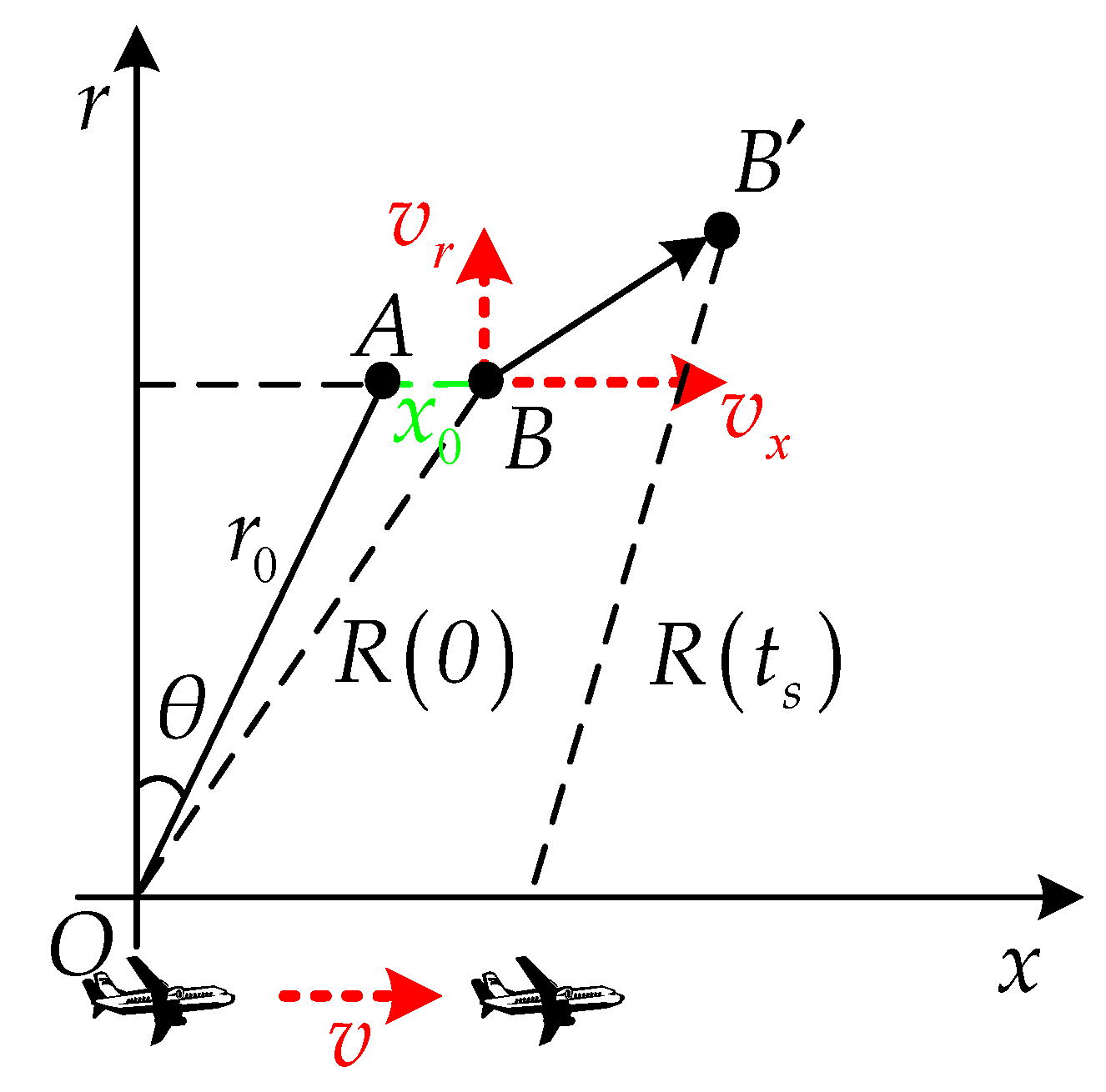
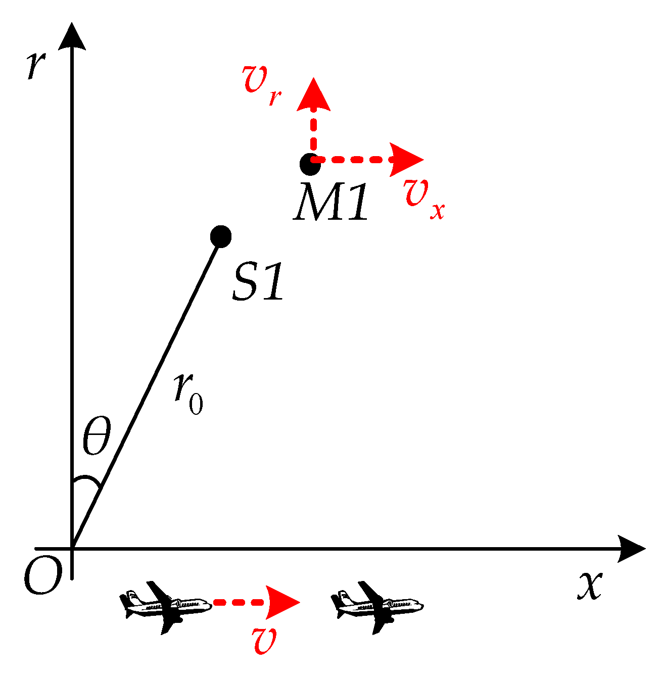
Consider the squint-looking SAR geometry as illustrated in Figure 1, where the x-axis is the azimuth direction and r-axis are the range direction. It is assumed that the SAR platform moves at the speed of v along the azimuth direction, the wave beam squint angle is . The range fast time and azimuth slow time are denoted as t and , respectively. The n-th pulse is transmitted at slow time , where T is the pulse repetition interval. When , the extended line of the wave beam center and the target line intersect at A, the distance between the SAR platform and A is . At B with the distance from A, there is a GMT whose azimuth and range velocity of GMT are and , respectively. Thus, the coordinate of the SAR platform and the GMT is and at , respectively. When the slow time is , the coordinate of SAR platform becomes and the GMT moves to .
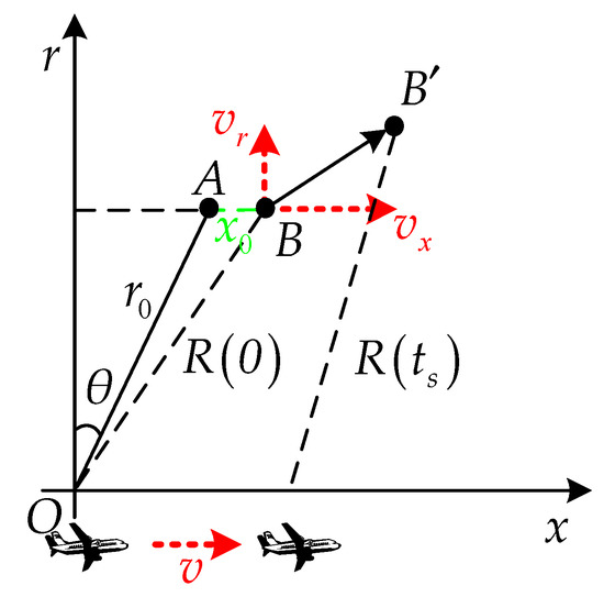
Figure 1.
2-D geometry model of SAR GMTIm with squint angle.
The instantaneous slant range between SAR platform and the GMT is expressed as
Assume that the radar transmits the linear frequency modulation (LFM) signal. Then the base band echo can be written as
where the is the rectangular function, is the pulse width, is the synthetic aperture time, is the carrier frequency, is the chirp rate, and is the target scatter coefficient that assumed to be a constant. c is the light speed. To derive the 2-D spectrum formular of the GMT echo, firstly obtain the range frequency domain and azimuth time domain signal by taking the range Fourier transform (FT) of
the azimuth FT of the signal can be expressed as
where and are range and azimuth frequency, respectively. According to the principle of stationary phase (POSP), the 2-D spectrum expression can be written as
where
To simplify the expression, envelope functions and scattering coefficient are ignored, which does not influence the following procedure. According to the RMA, the bulk focusing reference function of squint-looking SAR can be constructed as
where is the reference distance. Multiplied with Equation (9), Equation (5) becomes
It can be seen from Equation (10) that after the 2-D inverse Fourier transform (IFT) of Equation (10), the defocused GMT image can be obtained because of the existing of the high-order residual phase items. The level of defocus varies among the GMT which are in different position and with different velocity. For the stationary targets, the distance between the target point and the reference point becomes larger, the residual phase value is larger and the phenomenon of defocus becomes more severe. For GMT, in addition to the distance between the target point and the reference point, the velocity of GMT also affects the refocusing effect. The defocus caused by distance can be eliminated by accurate Stolt interpolation, while the defocus caused by velocity need to be solved by compensating for the residual phase related to velocity. The Stolt interpolation is expressed as
after adopting the Stolt interpolation, Equation (10) becomes
If the residual phase containing the unknown velocity is compensated, the refocused GMT image can be obtained immediately. However, due to the squint angle of SAR, the preliminary refocused GMT image still exists geometry distortion, thus geometry correction is needed. Next, sparsity enhancement is implemented to suppress the cross sidelobe of the GMT image. Geometry correction and sparsity enhancement is in the next section. For the problem of Doppler ambiguity which may occur in practice, detailed analysis has been stated in [38] and effective methods of removing Doppler ambiguity have been proposed by series of literatures [17,32,40]. Increasing the pulse repetition frequency (PRF) can also avoid the Doppler ambiguity. In this study, it is assumed that the Doppler ambiguity is removed by mature techniques.
3. Proposed Method for Highly Squint SAR GMTIm
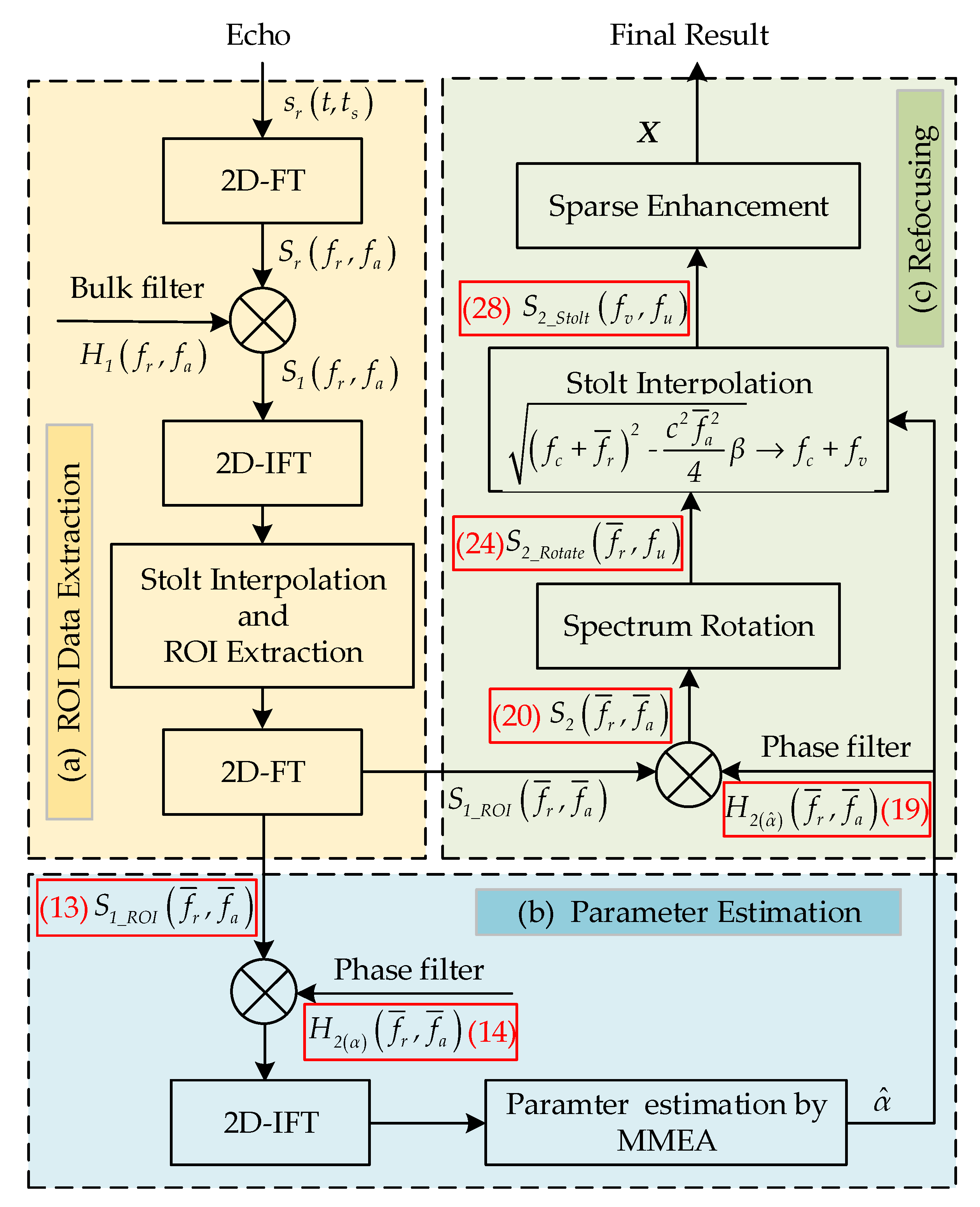
As is illustrated in Figure 2, the proposed method for GMTIm can be divided into three main steps: ROI data extraction, parameter estimation and refocusing. The main operation of ROI data extraction is extracting the GMT region within the preliminary image result after turning (12) into time domain. The key process of parameter estimation is the proposed MMEA method, which introduces the idea of bisection into the iteration minimum entropy algorithm to increase the iteration speed. MMEA firstly sets the parameter value range calculated by possible GMT velocity, and then shrinks the value range according to the first-order derivative of entropy until the value range is close to zero. Compensate the residual phase error with the phase compensation function containing the estimated parameter. Then, come to the refocusing step which has two main sub-steps: spectrum rotation and sparse enhancement. Spectrum rotation and sparse enhancement is used to eliminate the geometry distortion and suppress the sidelobe, respectively.
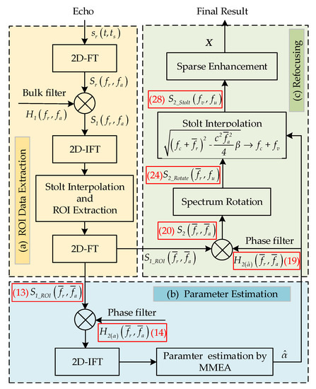
Figure 2.
Flow chart of proposed method.
The first step of the proposed method is extracting ROI data, which are the defocused complex sub-images containing the GMT. ROI data can be easily extracted from the whole SAR image and its 2-D frequency domain is expressed as
where and are range and azimuth frequencies of ROI data. Assume that the size of original data is , and the size of ROI data is , where , denote the range samples and , denote the azimuth samples. The ROI data usually occupy a small part of the original image, which means the volume of data is reduced. The next of the proposed method is on the basis of ROI data.
3.1. MMEA for Parameter Estimation
It can be seen from Equation (13) that the defocus effect of GMT mainly comes from which contains the unknown velocity of GMT and causes the phase error. When the residual phase error is compensated by the phase compensation function with the correct velocity and 2D IFT is conducted, the preliminary refocused GMT image is obtained. can be considered as a single parameter . In this section, MMEA is proposed to estimate the unknown parameter . The residual phase compensation function can be constructed as
where is the estimated phase compensation parameter and is the reference distance. Ideally, the estimated parameter is equivalent to the actual parameter. The residual phase compensation function can be written as a matrix when the parameter is given, and the preliminary refocusing procedure can be formulated through a series of transformation:
where and is the azimuth and range inverse Fourier transform matrix, respectively, is the matrix form of 2-D frequency domain ROI data and denote the Hadamard product. is the refocusing GMT image which is the function of parameter . The becomes the refocused image when the parameter is the correct one.
The key idea of minimum entropy algorithm is that the refocused GMT image has the minimum image entropy. Iterate the parameter until the GMT image reaches the minimum image entropy and the parameter of this time is the correct one. The GMT image entropy function is formulated as
where k is the base of the logarithm, and are the numbers of range and azimuth samples, respectively. is the pixel of n-th column and m-th row of the GMT image . It can be seen from Equations (15) and (16) that the GMT image entropy function is only determined by parameter , and the refocusing procedure can be also transformed to a optimization problem as
It is not easy to solve this problem directly. To convert this problem into a series of easier sub-problems, the IMEA constructs a surrogate function of (17). Different from IMEA, MMEA uses the idea of bisection to effectively obtain the optimal parameter . The parameter interval and the first-order derivative of at the bisection point are two key points of MMEA. MMEA has two main steps at every iteration. The first step is obtaining the parameter interval [a, b] according to the radar platform velocity v and possible GMT velocity [,]. Then calculate the first-order derivative of with respect to parameter at the bisection point . The first-order derivative of can be written as
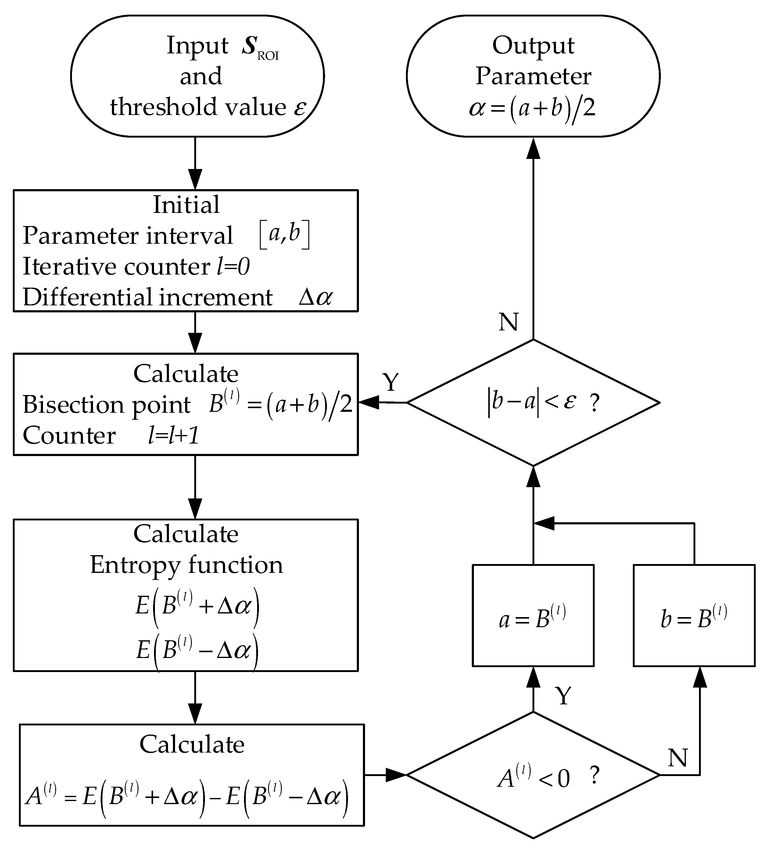
where and denote the imaginary and real parts of , respectively. The specific expression and derivation process can be found in Appendix A. The second step is updating the parameter interval according to the derivative sign of at the bisection point . Repeat the step 1 and step 2 until iterative converges. Convergence criterion is and the is the threshold value close to zero, which can be set according to the desired precision. However, to directly calculate the first-order derivative of may be time consuming because of the complexity of the formula. Notice that the sign of the first-order derivative of is enough for the parameter interval updating. To get this sign, set a differential increment on both sides of the bisection point, and calculate the
at the point and . Then the derivative sign of at the bisection point can be obtained by a subtraction between and . The details of the proposed MMEA for GMTIm are summarized in Figure 3.
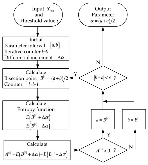
Figure 3.
Flow chart of proposed MMEA method.
3.2. Spectrum Rotation for Geometry Correction
After the parameter is estimated by MMEA, the corresponding phase compensation function can be constructed as
where the estimated is equal to actual in theory. Multiply with Equation (19), the compensated signal becomes Equation (20)
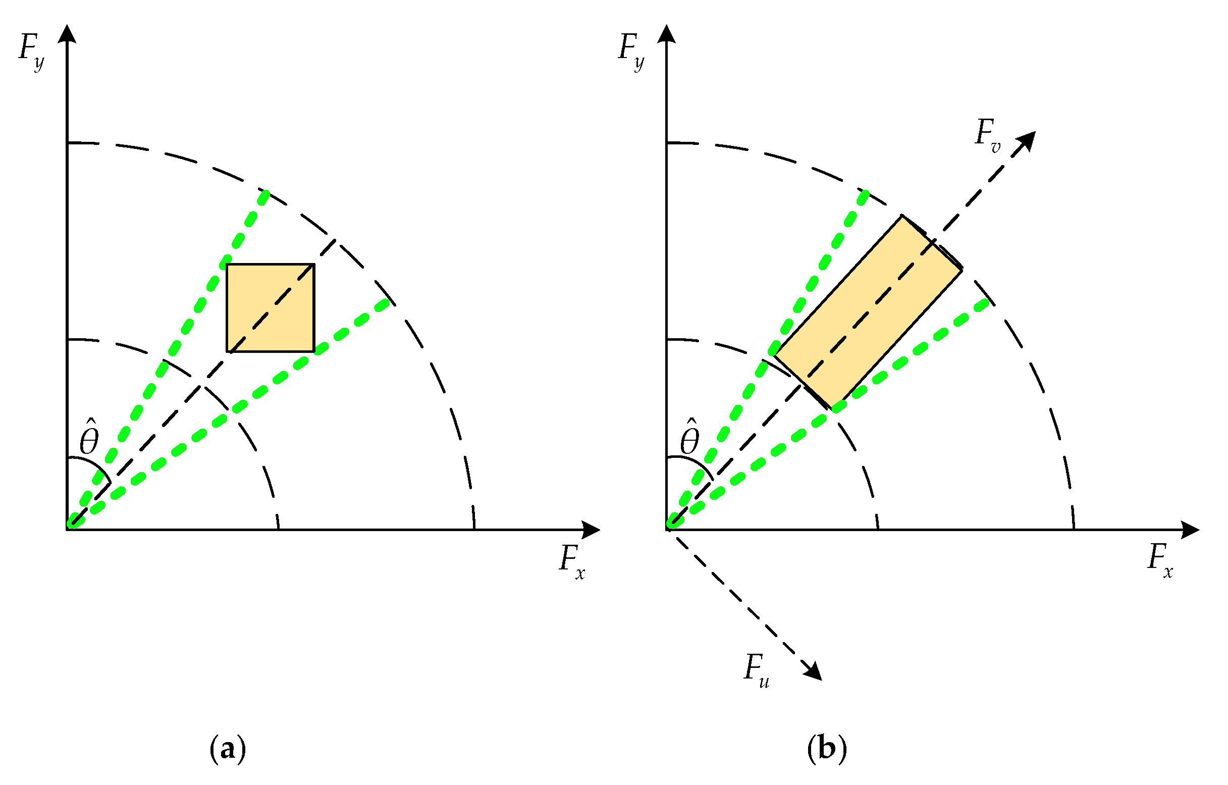
The refocused GMT image is obtained after adopting Stolt interpolation and 2-D IFT to Equation (20). However, Stolt interpolation need to select spectrum support region which is rectangle, and with the increase of the squint angle, the size of spectrum support region decreases. As is shown in Figure 4a, the spectrum support region reaches the minimum size when the squint angle is 45 degrees, and the size of spectrum support region increases when the squint angle continues to increase. In squint mode SAR, the decrease of spectrum support region may influence the image quality. Besides, the image exists geometry distortion after directly adopting Stolt interpolation and 2-D IFT to Equation (20) in squint mode.
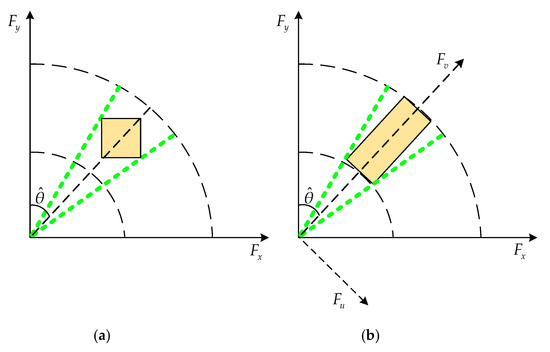
Figure 4.
(a) Spectrum support region selection before the spectrum rotation; (b) Spectrum support region selection after the spectrum rotation.
To get the maximum spectrum support region and remove the geometry distortion effect of GMT imaging, a spectrum rotation method is adopted. In this method, the rotation angle is the equivalent angle. As is shown in Figure 4b, the squinted 2-D spectrum is rotated into the side-looking form. For simplicity, set . In Figure 4, , , , .
In ordinary spectrum rotation method aiming at the stationary scene, the rotation angle is the squint angle. However, for GMTIm application, the rotation angle is not simply equal to the squint angel because both of the GMT and SAR platform have motion. Different from the traditional squint angle spectrum rotation (SASR) method, this method is called equivalent squint angle spectrum rotation (ESASR) method. One key point of ESASR is that how to calculate the rotation angle which is relevant to the shift of the Doppler center. To obtain the Doppler center, the imaging geometry model of GMT is analyzed firstly, as is shown in Figure 5. In squinted SAR, the Doppler center shift of the GMT echo consists of two parts, including the Doppler center shift caused by the platform moving speed and the Doppler center shift caused by the GMT velocity.
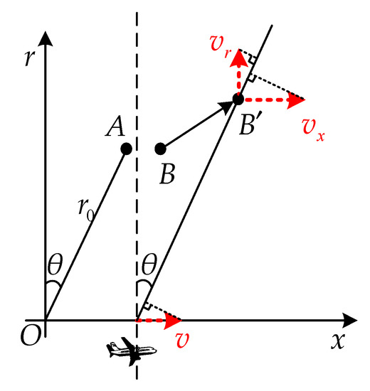
Figure 5.
Doppler centroid analysis.
From Figure 5 we know that and , the relationship of , and is . Then in analogy with the stationary scene rotation angle, the rotation angle of GMTIm is
where is the angle shown in Figure 4b, which can be called equivalent squint angle. When the GTM velocity is zero, , which means the rotation angle is equal to the squint angle. This is the condition of the stationary scene mentioned before. When the GMT has the velocity, the rotation angle is the equivalent squint angle . The Doppler center is obtained by Doppler center estimation method from the echo, rather than calculated by because the GMT velocity is unknown. To sum up, the spectrum rotation factor is
The spectrum rotation is achieved by the azimuth interpolation, the interpolation factor is
where . Additionally, after the spectrum rotation, Equation (20) becomes
where
After the spectrum rotation, adopt Stolt interpolation on Equation (24) with the which containing the estimated and correct parameter to eliminate the residual phase, the interpolation factor is
after the interpolation, Equation (24) becomes Equation (28)
after taking 2-D IFT of Equation (26), the refocused GMT image with no geometry distortion is obtained.
3.3. Sparsity Enhancement for Sidelobe Suppression
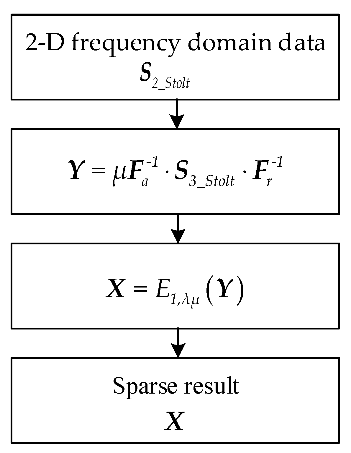
Notice that the GMT image is usually sparse in space domain. If the GMT image is constrained with sparsity and the 2-D IFT is replaced by sparsity reconstruction, the sidelobe can be suppressed further. The process of reconstructing the GMT sparse result is represented as a L1 norm optimization problem
where and are the azimuth and range FT matrix, respectively. is the GMT sparse image. This optimization problem can be effectively solved by iterative threshold algorithm (ITA). The GMT sparse result at every iteration is
where and are the range and azimuth IFT matrix, respectively. is the parameter related to iteration convergency. E denotes the thresholding operator
For the full sampled data, the GMT sparse result is obtained through only one iteration. Suppose that the sparse result is zero, then the algorithm of the sparsity enhancement is shown as Figure 6.

Figure 6.
Algorithm flow of sparse enhancement.
4. Results
In this section, simulated data and measured ship data are used to give experiments of the proposed GMTIm algorithm. Section 4.1 is the experiment of a simulated scene. The simulated scene consists of two point targets. The process of GMTIm algorithm is displayed, including the conventional imaging results by RMA, focused GMT image without or with the spectrum rotation and their respective sparse enhancement image. Section 4.2 is the experiment of measured ship data collected by spaceborne SAR platform. The data cannot be directly used because it is side-looking mode and the proposed algorithm is aimed at squint mode. The side-looking SAR ship data are reused to form the squint SAR ship data. The quality of the refocused GMT image is analyzed in both simulated data and ship data experiment, and the effectiveness of the proposed GMTIm algorithm is demonstrated.
4.1. GMTIm Based on Simulated Data
In this section, simulated point targets data are used to analyze the performance of the proposed algorithm. As is shown in Figure 7, the point targets scene is comprised of two scatterers: moving target M1 and stationary target S1. The range and azimuth velocity of M1 are and , respectively. The radar platform flies at the velocity of 150 m/s and the other parameters of radar are: the signal center frequency is 10 GHz, the bandwidth is 75 MHz, the pulse duration is 2.2 , and the pulse repetition frequency (PRF) is 3000 Hz, the scene center range is 5000 m and the squint angle are 45, 60, 75 degrees.

Figure 7.
Point targets scene.
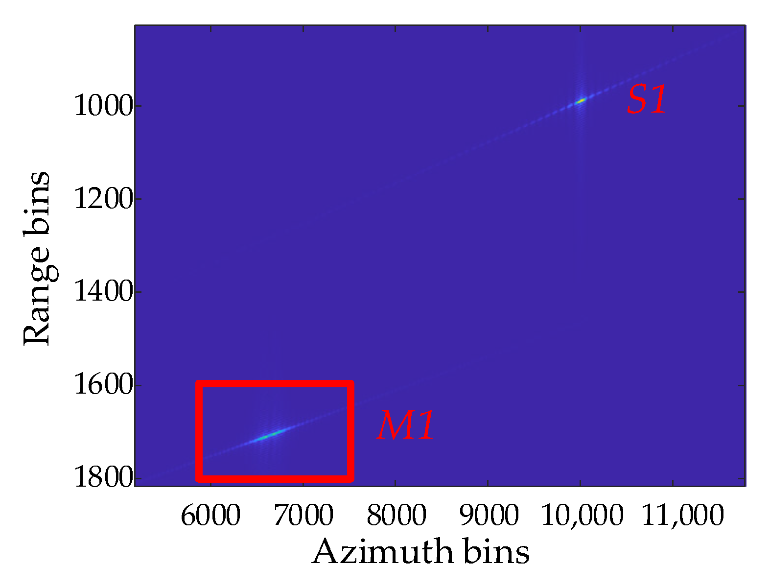
Figure 8 is the conventional RMA imaging results of point targets. The moving target M1 is defocused compared to S1 before the residual phase is compensated. The following procedure is based on the GMT ROI data which are indicated by the red dash box. According to the proposed algorithm, the ROI data from conventional imaging result are firstly transformed into 2-D frequency domain and then turned into the MMEA parameter estimation step.

Figure 8.
Conventional RMA imaging results of point targets.
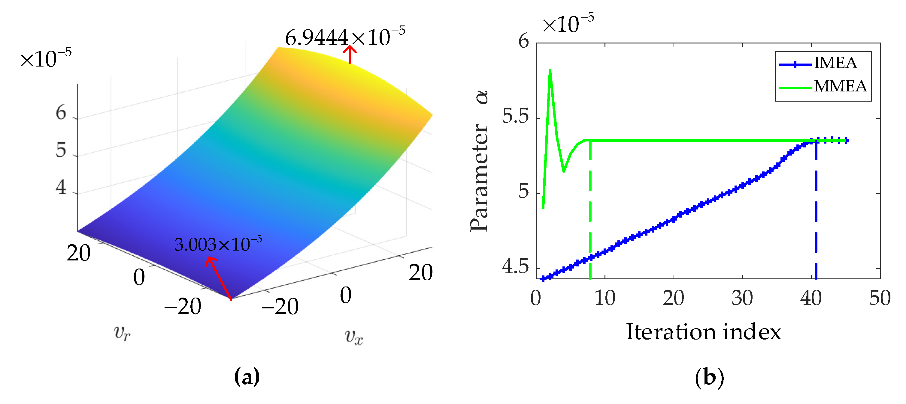
First step of MMEA is to obtain the initial parameter interval. In most of the practical situations, the GMT velocity is less than 30 m/s. As is shown in Figure 9a, according to and different velocity pair [, ], the initial parameter interval is easily obtained, that is [, ]. The parameter iteration comparison graph of MMEA and IMEA is shown in Figure 9b, from which we can see MMEA and IMEA reach the same estimated parameter . However, IMEA iterated over 40 times to reach the final parameter, while the proposed MMEA iterated less than 10 times. The reason why MMEA cost such a few iterations is that the parameter interval shrinks to the half range in every iteration and the optimal parameter is guaranteed within the parameter interval all the time. If the initial parameter is set properly, IMEA can also converges fast. The problem for IMEA is that it is difficult to set the proper parameter due to the unknown GMT motion. The MMEA does not need to set an initial parameter but a parameter value range which is irrelevant to the actual GMT motion.

Figure 9.
(a) Parameter value range; (b) The GMT parameter iteration graph of MMEA and IMEA.
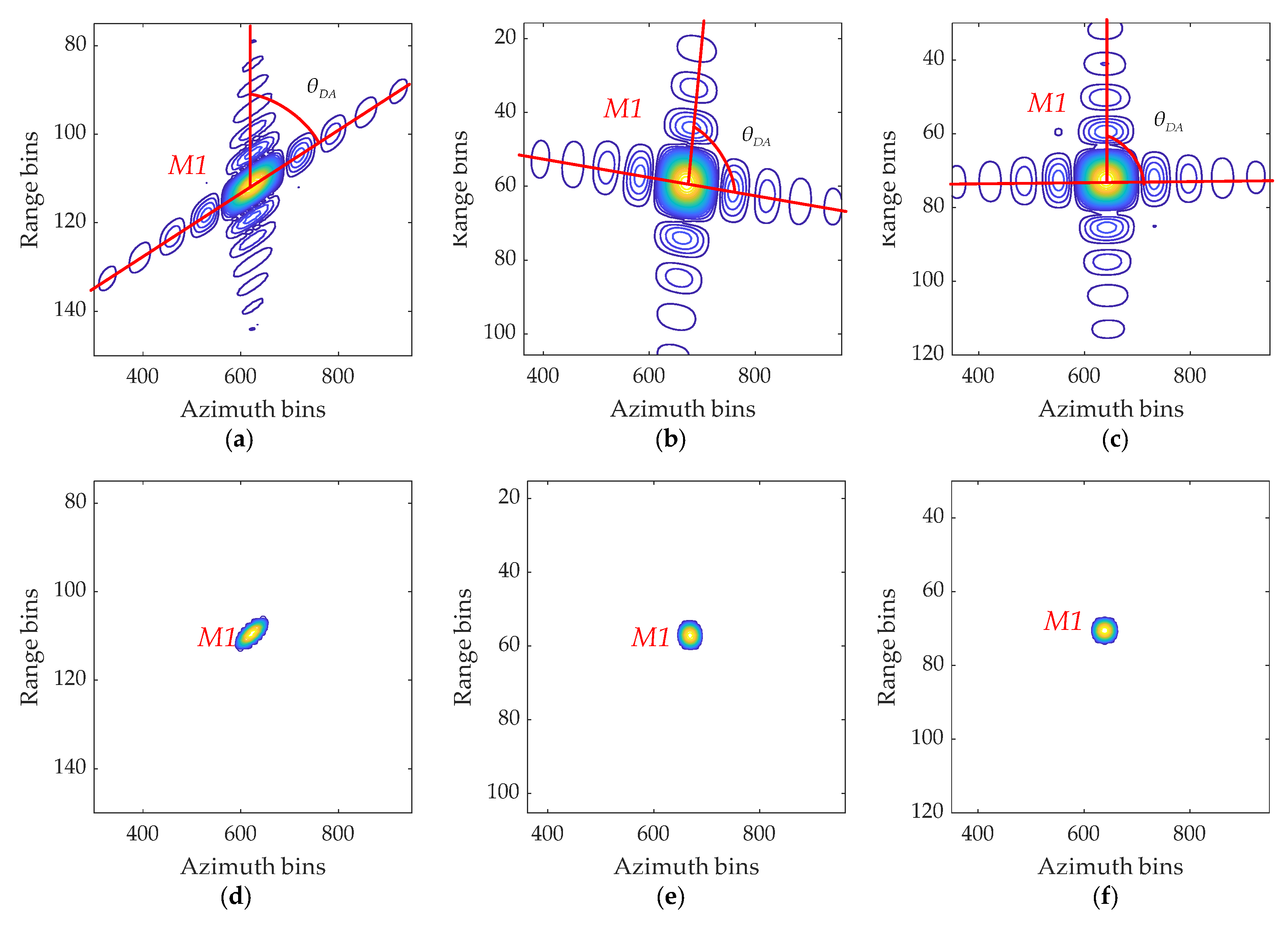
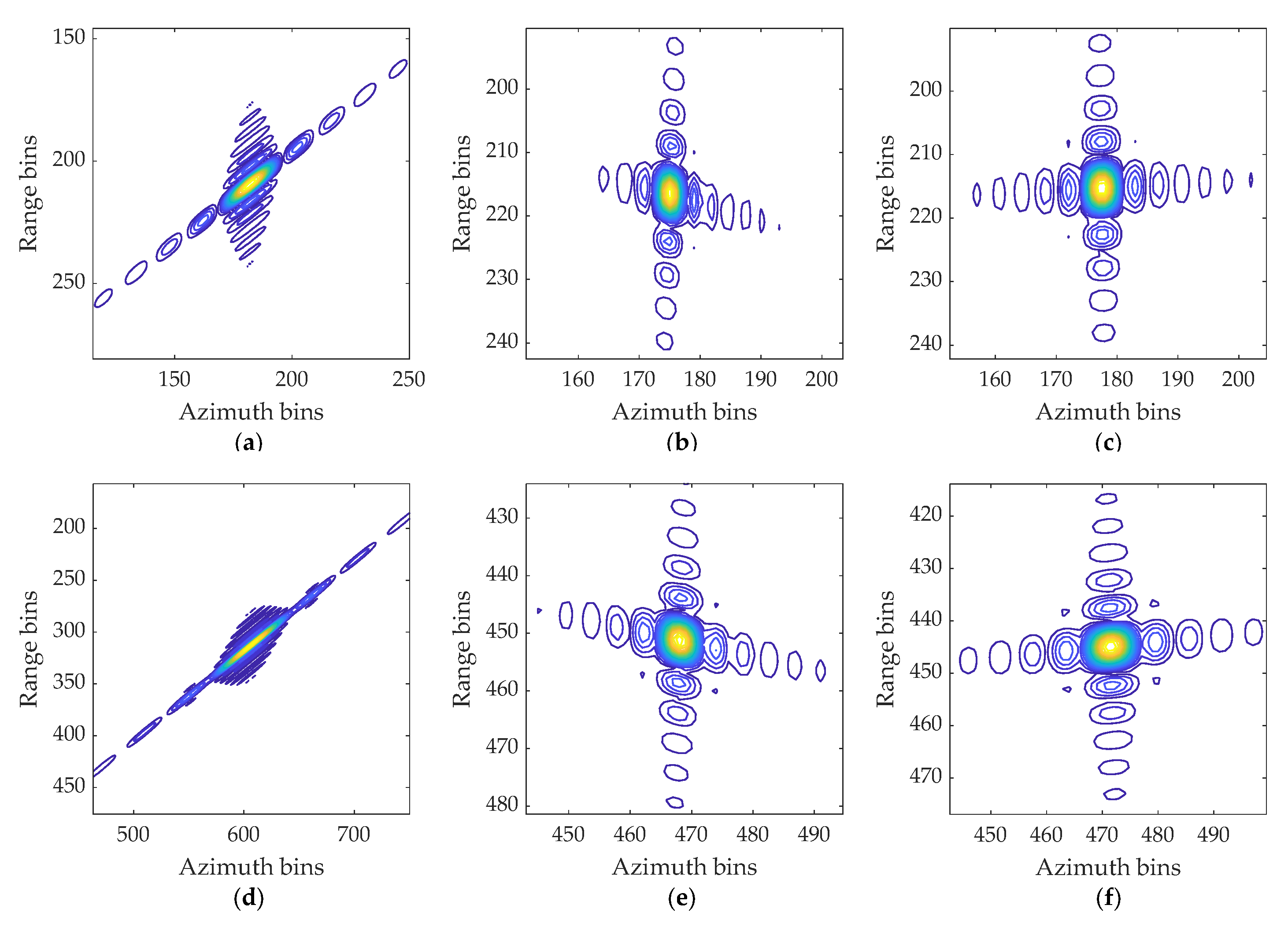
Compensate the residual phase error of the GMT defocused image, we get the GMT focused image and sparse enhancement image with or without spectrum rotation, which is shown in Figure 10. In Figure 10a, the focused GMT image without spectrum rotation has severe geometry distortion that the point-like GMT turns into ellipse-like GMT. Accordingly, in Figure 10d, the sparse enhancement image of the line-like GMT image is also ellipse-like. As is shown in Figure 10b, although a part of the geometry distortion can be corrected by SASR, there still exists some distortion residual. As is shown in Figure 10c,f, the geometry distortion is almost corrected by ESASR and the corresponding sparse enhancement result has a low sidelobe.
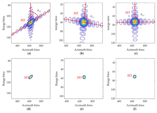
Figure 10.
Moving target focused image and sparse enhancement image with or without spectrum rotation: (a) Focused image without spectrum rotation; (b) Focused image with SASR; (c) Focused image with ESASR; (d–f) Sparse enhancement image of (a–c), respectively.
As is mentioned before, MMEA converges faster than IMEA in the aspect of refocusing. The spectrum rotation is needed to correct the geometry distortion. To further evaluate the performance of the spectrum rotation method, the imaging quality indexes of MMEA, MMEA+SASR, MMEA+ESASR are quantified as shown in Table 1. The quality indexes include peak side-lobe ratio (PSLR), integrated side-lobe (ISLR), and distortion angle (DA) which is denoted as . The is defined as the angle of the cross side-lobe, as is shown in Figure 10a–c. Evidently, compared with the MMEA and MMEA+SASR, the result of MMEA+ESASR are more similar to the ideal value of PSLR, ISLR, and especially the DA. It means MMEA+ESASR achieves precise focusing of the GMT and corrects a large proportion of the geometry distortion.

Table 1.
Comparison of imaging quality indexes.
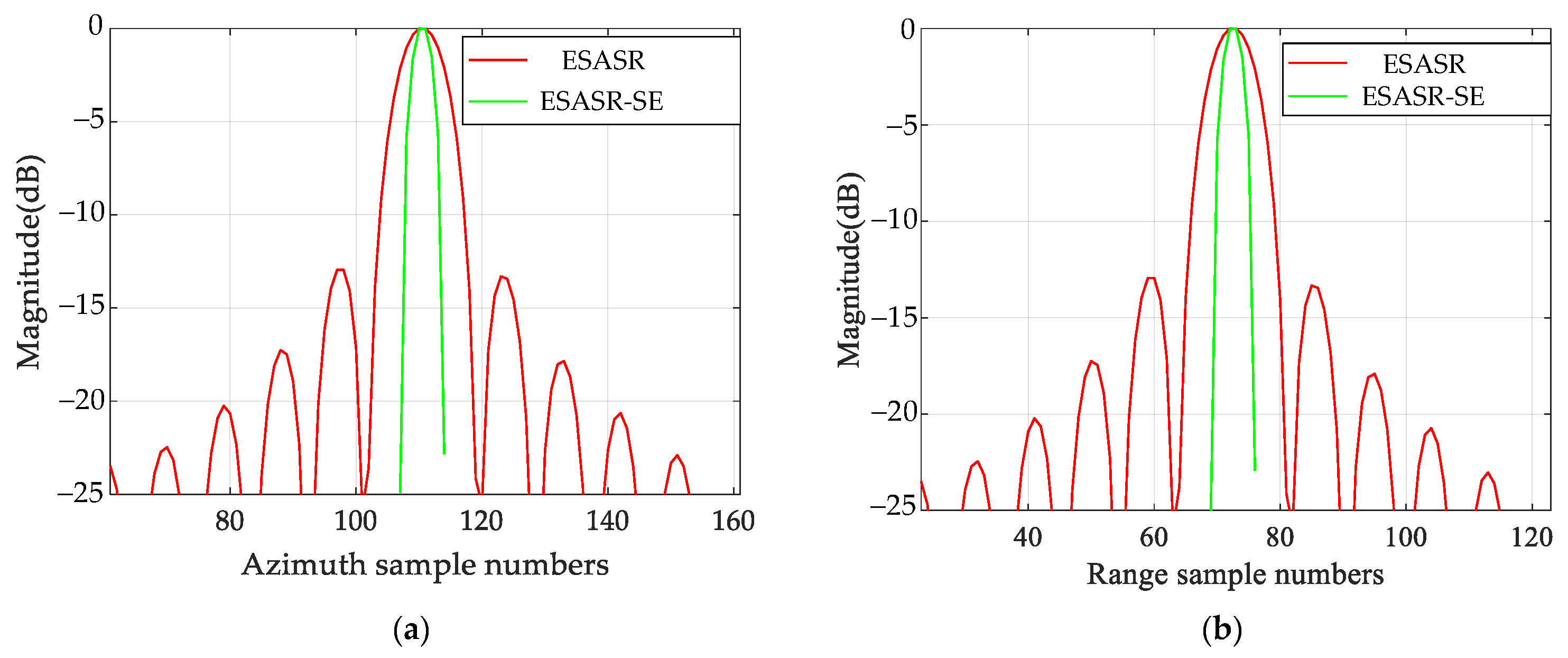
The point target response in azimuth and range profile of the GMT image with ESASR and its sparse enhancement (SE) image are shown in Figure 11, where the red line denotes the point target response of GMT with ESASR and the green line denotes the ESASR-SE result. The ESASR-SE results have a narrower main lobe and lower side lobe than the refocused GMT image without sparse enhancement.
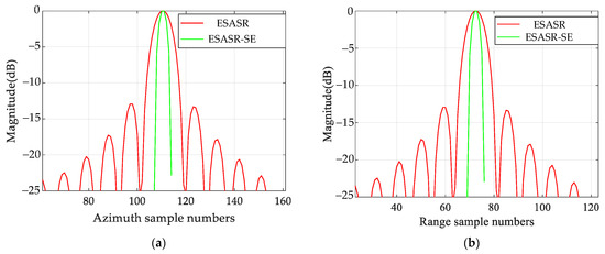
Figure 11.
Point target response in azimuth and range profile of ESASR, ESASR-SE: (a) Point target response in azimuth profile; (b) Point target response in range profile.
To demonstrate the proposed algorithm works in situation of higher squint angle, the following experiments is implemented when the squint angle are 60 or 75 degrees. As is shown in Figure 12, the focused GMT image is displayed after the MMEA. Before the spectrum rotation is used, the target geometry distortion becomes more severe with the increase of squint angle. The point-like target nearly turns into line-like. When the SASR is implemented, the target geometry distortion is relieved a little, while the ESASR can eliminates almost all the distortion. The following procedure is the sparce enhancement which is the same as part A. Table 2 is the comparison of distortion angle.
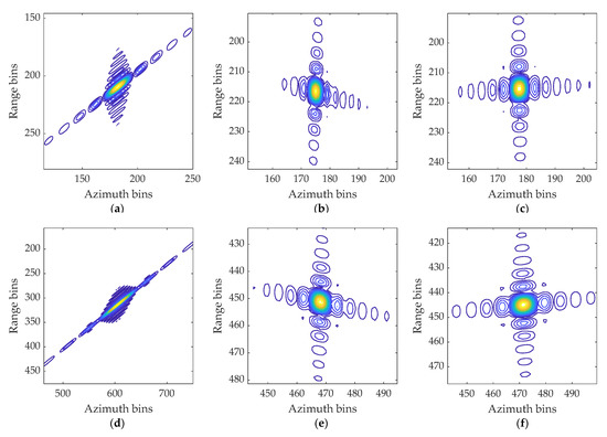
Figure 12.
Moving target focused image and sparse enhancement image with or without spectrum rotation: (a) Focused image without spectrum rotation; (b) Focused image with SASR; (c) Focused image with ESASR; (d–f) Sparse enhancement image of (a–c), respectively.
Table 2.
Comparison of distortion angle.
4.2. GMTIm Based on GF-3 Data
The original SAR data of ship target are collected by a side-looking SAR platform GF-3 satellite [14]. To make the side-looking SAR data suitable for the squint SAR experiments, ship target data are used to calculate the scattering echoes of squint mode SAR. The motion parameter of the ship target is [, ] = [5 m/s,10 m/s]. The radar platform flies at a 10 km height with a speed of 150 m/s. The down-sight angle is 60 degrees. The other parameters of radar are: the signal center frequency is 10 GHz, the bandwidth is 150 MHz, the pulse duration is 2.2 , and the pulse repetition frequency (PRF) is 1275 Hz, the scene center range is 5000 m, the radar operates in squint-look mode with squint angle 50 degrees.
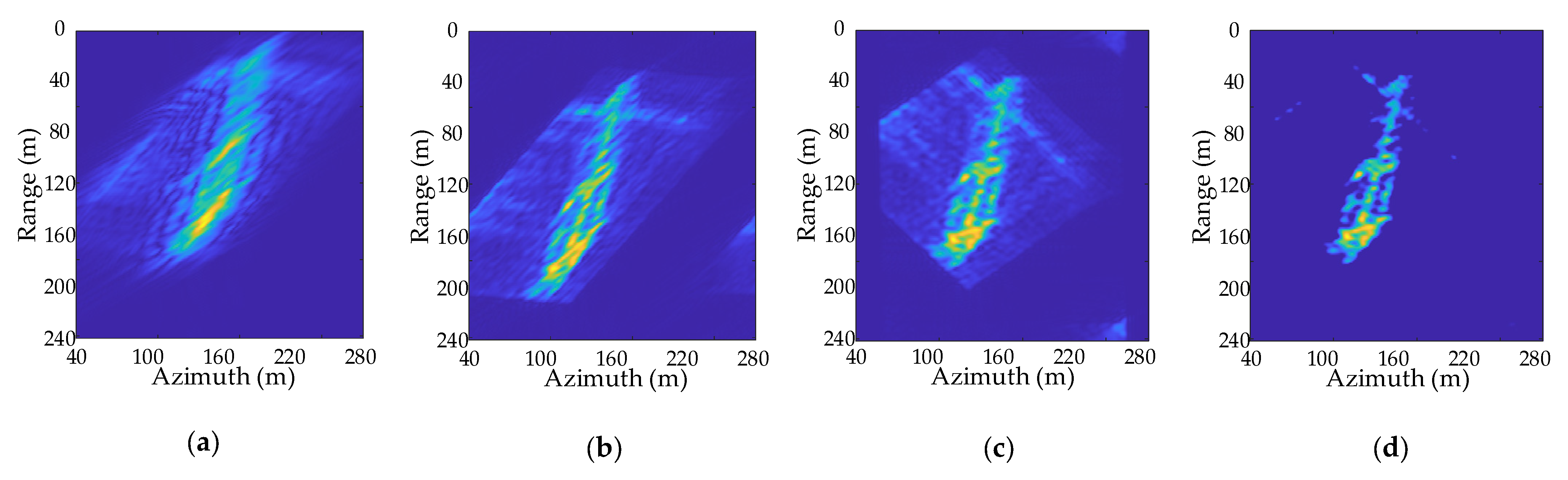
The ROI data extraction and parameter estimation process is shown in Figure 13. The GMT ROI data are indicated by the red dashed box in Figure 13a which is the conventional RMA imaging result. The parameter iteration process of MMEA and IMEA is made a contrast in Figure 13b, and the estimated parameter is . MMEA iterated only 9 times to reach the final parameter, which is less than that of IMEA. Figure 14a is the defocused ROI image. As is shown in Figure 14b, after the residual phase compensation operation, the focused image without spectrum rotation is obtained. There is some influence of the geometry distortion on the target recognition application. After the spectrum rotation, the geometry distortion of the GMT is corrected and the focused image is shown in Figure 14c. Even if there exists some orientation difference from the actual ship target, it is easier to accomplish the target recognition. The final result shown in Figure 14d is the sparse enhancement result whose sidelobe is suppressed and target characteristic is more distinct.
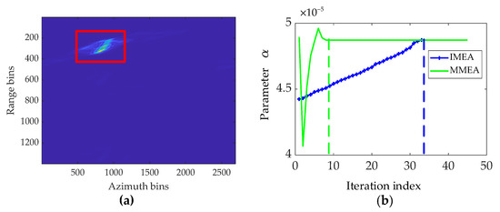
Figure 13.
(a) Conventional RMA imaging results of ship target; (b) The GMT parameter iteration graph of MMEA and IMEA.
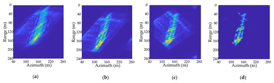
Figure 14.
Ship target refocusing process in Squint-looking SAR: (a) Defocused ROI image; (b) Focused image without spectrum rotation; (c) Focused image with ESASR; (d) Image of sparse enhancement.
5. Conclusions
In this paper, a GMTIm method for the squint mode SAR was proposed, which had the following steps: ROI data extraction, parameter estimation by MMEA, residual phase compensation, spectrum rotation, and sparse enhancement. The ROI data of the GMT were extracted from the preliminary SAR image of the RMA. In squint SAR, the RMA signal model of the GMT was derived, and the accurate residual phase compensation was achieved because of the accurate slant range model of the RMA. The ROI data were useful for decreasing the processing data volume and restraining the clutter at the same time. The parameter estimation step took advantage of the idea of bisection to boost up the convergence speed of the minimum entropy algorithm. The new efficient minimum entropy algorithm is called MMEA. After the residual phase compensation by the compensation function with the estimated parameter, the refocused GMT image was obtained. Spectrum rotation method ESASR corrected the geometry distortion of the GMT image, which was helpful for the target recognition application. The final sparse enhancement step fully made use of the GMT sparsity to further suppress the GMT image sidelobe. Experiment results validate the effectiveness of the proposed method on GMTIm in squint mode SAR. The simulated targets move with a constant velocity, which may not conform the physical truth that the targets have a complicated motion. This will be our future work.
Author Contributions
Conceptualization and methodology, S.X. and J.N.; software, S.X.; resources, Q.Z and Y.L.; writing—review and editing, S.X., J.N., Q.Z. and L.Y. All authors have read and agreed to the published version of the manuscript.
Funding
This research was funded by the National Nature Science Foundation of China under Grant 62001508, 62131020 and 62001505, and in part by the Natural Science Basic Research Program of Shaanxi under grant 2020JQ-480 and 2020JQ-469.
Acknowledgments
The authors would like to thank all reviewers and editors for their comments on this paper.
Conflicts of Interest
The authors declare no conflict of interest.
Appendix A
The first-order derivative of the entropy function with respect to can be expanded as (A1)
where and denote the imaginary and real parts of , respectively. According to Equation (15), we have
where m, n, p and q denote the index of matrix elements. As , ,and are irrelevant to the phase compensation parameter, we have
The real and imaginary parts of are denoted as and , respectively. According to Euler formula, Equation (A2) is equal to
where denotes the phase of (see Equation (14)). Accordingly, the real and imaginary parts of can be expressed as
Then the first-order derivatives of and with respect to can be written as Equations (A7) and (A8), respectively.
where
we can obtain the first-order derivative of the entropy function with respect to by substituting Equations (A5)–(A9) into Equation (A1).
References
- Werness, S.A.S.; Carrara, W.G.; Joyce, L.S.; Franczak, D.B. Moving Target Imaging Algorithm for SAR Data. IEEE Trans. Aerosp. Electron. Syst. 1990, 26, 57–67. [Google Scholar] [CrossRef]
- Çetin, M.; Stojanovi´c, I.; Önhon, Ö.; Varshney, K.; Samadi, S.; Karl, W.C.; Willsky, A.S. Sparsity-Driven Synthetic Aperture Radar Imaging: Reconstruction, Autofocusing, Moving targets, and Compressed Sensing. IEEE Signal. Process. Mag. 2014, 31, 27–40. [Google Scholar] [CrossRef]
- Graziano, M.D.; D’Errico, M.; Rufino, G. Wake Component Detection in X-band SAR Images for Ship Heading and Velocity Estimation. Remote Sens. 2016, 8, 498. [Google Scholar] [CrossRef] [Green Version]
- Zhao, Y.; Han, S.; Yang, J.; Zhang, L.; Xu, H.; Wang, J. A Novel Approach of Slope Detection Combined with Lv’s Distribution for Airborne SAR Imagery of Fast Moving Targets. Remote Sens. 2018, 10, 764. [Google Scholar] [CrossRef] [Green Version]
- Song, C.; Wang, B.; Xiang, M.; Wang, Z.; Xu, W.; Sun, X. A Novel Post-Doppler Parametric Adaptive Matched Filter for Airborne Multichannel Radar. Remote Sens. 2020, 12, 4017. [Google Scholar] [CrossRef]
- Chen, J.; Xing, M.; Yu, H.; Liang, B.; Peng, J.; Sun, G. Motion Compensation/Autofocus in Airborne Synthetic Aperture Radar: A Review. IEEE Geosci Remote Sens. Mag. 2021, 2–23. [Google Scholar] [CrossRef]
- Perry, R.P.; DiPietro, R.C.; Fante, R. SAR Imaging of Moving Targets. IEEE Trans. Aerosp. Electron. Syst. 1999, 35, 188–200. [Google Scholar] [CrossRef]
- Kirscht, M. Detection and Imaging of Arbitrarily Moving Targets with Single-Channel SAR. IET Radar Sonar Navig. 2003, 150, 7–11. [Google Scholar] [CrossRef]
- Henke, D.; Magnard, C.; Frioud, M.; Small, D.; Meier, E.; Schaepman, M.E. Moving-Target Tracking in Single-Channel Wide-Beam SAR. IEEE Trans. Geosci. Remote Sens. 2012, 50, 4735–4747. [Google Scholar] [CrossRef] [Green Version]
- Jin, G.H.; Dong, Z.; He, F.; Yu, A.X. Background-Free Ground Moving Target Imaging for Multi-PRF Airborne SAR. IEEE Trans. Geosci. Remote Sens. 2019, 57, 1949–1962. [Google Scholar] [CrossRef]
- Gu, F.F.; Zhang, Q.; Chen, Y.C. Parametric Sparse Representation Method for Motion Parameter Estimation of Ground Moving Target. IEEE Sens. J. 2016, 16, 7646–7652. [Google Scholar] [CrossRef]
- Pascazio, V.; Schirinzi, G.; Farina, A. Moving Target Detection by Alongtrack Interferometry. In Proceedings of the IEEE IGARSS, Sydney, NSW, Australia, 9–13 July 2001; pp. 3024–3026. [Google Scholar] [CrossRef]
- Suwa, K.; Yamamoto, K.; Tsuchida, M.; Nakamura, S.; Wakayama, T.; Hara, T. Image-Based Target Detection and Radial Velocity Estimation Methods for Multichannel SAR-GMTI. IEEE Trans. Geosci. Remote Sens. 2017, 55, 1325–1338. [Google Scholar] [CrossRef]
- Chen, Y.; Li, G.; Zhang, Q.; Sun, J. Refocusing of Moving Targets in SAR Images via Parametric Sparse Representation. Remote Sens. 2017, 9, 795. [Google Scholar] [CrossRef] [Green Version]
- Martorella, M.; Giusti, E.; Berizzi, F.; Bacci, A.; Mese, E.D. ISAR based technique for refocusing non-cooperative targets in SAR images. IET Radar Sonar Navig. 2012, 6, 332–340. [Google Scholar] [CrossRef]
- Zhang, Y.; Sun, J.; Lei, P.; Li, G.; Hong, W. High-Resolution SAR-Based Ground Moving Target Imaging with Defocused ROI Data. IEEE Trans. Geosci. Remote Sens. 2016, 54, 1062–1073. [Google Scholar] [CrossRef]
- Zhou, F.; Wu, R.; Xing, M.; Bao, Z. Approach for Single Channel SAR Ground Moving Target Imaging and Motion Parameter Estimation. IET Radar Sonar Navig. 2007, 1, 59–66. [Google Scholar] [CrossRef]
- Li, G.; Xia, X.G.; Peng, Y.N. Doppler Keystone Transform-An Approach Suitable for Parallel Implementation of SAR Moving Target Imaging. IEEE Geosci. Remote Sens. Lett. 2008, 5, 573–577. [Google Scholar] [CrossRef]
- Jin, G.H.; Dong, Z.; He, F.; Yu, A.X. SAR Ground Moving Target Imaging Based on a New Range Model Using a Modified Keystone Transform. IEEE Trans. Geosci. Remote Sens. 2019, 57, 3283–3295. [Google Scholar] [CrossRef]
- Wan, J.; Tan, X.; Chen, Z.; Li, D.; Liu, Q.; Zhou, Y.; Zhang, L. Refocusing of Ground Moving Targets with Doppler Ambiguity Using Keystone Transform and Modified Second-Order Keystone Transform for Synthetic Aperture Radar. Remote Sens. 2021, 13, 177. [Google Scholar] [CrossRef]
- Djurovic, I.; Thayaparan, T.; Stankovic, L. SAR Imaging of Moving Targets Using Polynomial Fourier Transform. IET Signal Process. 2008, 2, 237–246. [Google Scholar] [CrossRef] [Green Version]
- Chen, X.L.; Guan, J.; Chen, W.S.; Zhang, L.; Yu, X.H. Sparse Long-Time Coherent Integration-Based Detection Method for Radar Low-Observable Maneuvering Target. IET Radar Sonar Navig. 2020, 14, 538–546. [Google Scholar] [CrossRef]
- Huang, P.H.; Xia, X.G.; Gao, Y.S.; Liu, X.Z.; Liao, G.S.; Jiang, X. Ground Moving Target Refocusing in SAR Imagery Based on RFRT-FrFT. IEEE Trans. Geosci. Remote Sens. 2019, 57, 5476–5492. [Google Scholar] [CrossRef]
- Matan, L.; George, P.; Chrysoula, T. Low Rank Plus Sparse Decomposition of Synthetic Aperture Radar Data for Target Imaging. IEEE Trans. Comput. Imaging. 2020, 6, 491–502. [Google Scholar] [CrossRef]
- Kang, M.S.; Kim, K.T. Ground Moving Target Imaging Based on Compressive Sensing Framework with Single-Channel SAR. IEEE Sens. J. 2020, 20, 1238–1250. [Google Scholar] [CrossRef]
- Chen, Y.C.; Li, G.; Zhang, Q. Iterative Minimum Entropy Algorithm for Refocusing of Moving Targets in SAR Images. IET Radar Sonar Navig. 2019, 13, 1279–1286. [Google Scholar] [CrossRef]
- Li, Z.Y.; Liang, Y.; Xing, M.D.; Huai, Y.Y.; Gao, Y.X.; Zeng, L.T.; Bao, Z. An Improved Range Model and Omega-K-Based Imaging Algorithm for High-Squint SAR With Curved Trajectory and Constant Acceleration. IEEE Geosci. Remote Sens. Lett. 2016, 13, 656–660. [Google Scholar] [CrossRef]
- Yang, L.; Zhao, L.F.; Zhou, S. Sparsity-Driven SAR Imaging for Highly Maneuvering Ground Target by the Combination of Time-Frequency Analysis and Parametric Bayesian Learning. IEEE J. Sel. Topics Appl. Earth Observ. Remote Sens. 2017, 10, 1443–1455. [Google Scholar] [CrossRef]
- Xin, Z.H.; Liao, G.S.; Yang, Z.W.; Huang, P.H.; Ma, J.T. A fast ground moving target focusing method based on first-order discrete polynomial-phase transform. Digit. Signal Process. 2017, 60, 287–295. [Google Scholar] [CrossRef]
- Tian, M.; Liao, G.; Zhu, S.; He, X.; Liu, Y.; Li, Y. An Efficient Method for Ground Maneuvering Target Refocusing and Motion Parameter Estimation Based on DPT–KT–MFP. Remote Sens. 2021, 13, 1092. [Google Scholar] [CrossRef]
- Cumming, I.G.; Wong, F.H. Digital Processing of Synthetic Aperture Radar Data: Algorithm and Implementation; Artech House: Norwood, MA, USA, 2005. [Google Scholar]
- Yang, J.; Liu, C.; Wang, Y. Imaging and parameter estimation of fast-moving targets with single-antenna SAR. IEEE Geosci. Remote Sens. Lett. 2014, 11, 529–533. [Google Scholar] [CrossRef]
- Jing, K.; Xu, J.; Hang, Z.; Yao, D.; Long, T. GMTI for Squint Looking XTI-SAR with Rotatable Forward-Looking Array. Sensors 2016, 16, 873. [Google Scholar] [CrossRef] [PubMed] [Green Version]
- Wang, Y.; Cao, Y.H.; Qi, C.; Han, J.S.; Liu, Y.T. Multi-channel SAR-GMTI Clutter Suppression Method Based on Hypersonic Platform Forward Squint. J. Electron. Inf. Technol. 2020, 42, 458–464. [Google Scholar]
- Xiong, B.; Xu, J.; Peng, S.; Yang, J. Ground moving targets signal modeling for multi-channel squint-looking SAR. In Proceedings of the International Radar Conference, Xi’an, China, 14–16 April 2013; pp. 1–7. [Google Scholar]
- Han, J.; Cao, Y.; Yeo, T.-S.; Wang, F. Robust Clutter Suppression and Ground Moving Target Imaging Method for a Multi-channel SAR with High-Squint Angle Mounted on Hypersonic Vehicle. Remote Sens. 2021, 13, 2051. [Google Scholar] [CrossRef]
- Garren, D.A. Signature morphology effects of squint angle for arbitrarily moving surface targets in spotlight synthetic aperture radar. IEEE Trans. Geosci. Remote Sens. 2015, 53, 6241–6251. [Google Scholar] [CrossRef]
- Chen, Z.; Zhou, Y.; Zhang, L.; Lin, C.; Huang, Y.; Tang, S. Ground Moving Target Imaging and Analysis for Near-Space Hypersonic Vehicle-Borne Synthetic Aperture Radar System with Squint Angle. Remote Sens. 2018, 10, 1966. [Google Scholar] [CrossRef] [Green Version]
- Bi, H.; Bi, G.A.; Zhang, B.C.; Hong, W.; Wu, Y.R. From Theory to Application: Real-Time Sparse SAR Imaging. IEEE Trans. Geosci. Remote Sens. 2020, 58, 2928–2936. [Google Scholar] [CrossRef]
- He, X.P.; Liao, G.S.; Zhu, S.Q.; Xu, J.W.; Guo, Y.F.; Wei, J.Q. Fast Non-Searching Method for Ground Moving Target Refocusing and Motion Parameters Estimation. Digit. Signal Process. 2018, 79, 152–163. [Google Scholar] [CrossRef]


Publisher’s Note: MDPI stays neutral with regard to jurisdictional claims in published maps and institutional affiliations. |
© 2021 by the authors. Licensee MDPI, Basel, Switzerland. This article is an open access article distributed under the terms and conditions of the Creative Commons Attribution (CC BY) license (https://creativecommons.org/licenses/by/4.0/).