Abstract
Renewable methanol is considered a promising carrier for sustainable hydrogen due to its convenience in storage and transportation. Methanol steam reforming (MSR) using exhaust heat from industrial boilers can further enhance energy efficiency. However, existing methanol reforming systems still face challenges in terms of matching with industrial boilers, heat exchanger compactness, and adaptability to fluctuations in exhaust gas conditions. To address these issues, this study proposes the design of a modular methanol reforming system driven by the exhaust heat of small industrial boilers and develops a three-dimensional multiphysics simulation model to investigate the heat transfer and reaction characteristics within the reactor. The results indicate that, within the ranges of exhaust heat temperature (220–270 °C), flow rate (0.4–1.2 g/s), and channel spacing (60–100 mm), increasing the exhaust heat temperature enhances the endothermic reforming process, while decreasing the channel spacing improves heat transfer and increases methanol conversion. The reactor with a 60 mm channel spacing achieves a conversion ratio of up to 95.3% at a flow rate of 0.4 g/s. Although the hydrogen yield increases with flow rate, the single-pass conversion ratio decreases due to shorter residence time and increased load per unit volume. Compared to traditional fixed-structure reactors, the proposed modular system allows flexible matching of scale and heat exchange capacity through adjustable channel configurations, enhancing adaptability to fluctuations in industrial exhaust temperature and load. This design improves the utilization efficiency of low-grade waste heat and offers a practical engineering solution for sustainable distributed hydrogen production.
1. Introduction
With the continuous increase in global fossil fuel consumption, the extensive use of conventional energy sources such as gasoline and diesel in the transportation and industrial sectors has led to a sharp rise in greenhouse gas emissions and a worsening of environmental pollution [1]. This energy structure, which relies heavily on non-environmentally friendly fuels, not only accelerates climate change but also leads to serious air pollution problems, which pose significant threats to human health [2,3]. This situation runs counter to the global pursuit of sustainable development goals, highlighting the urgent need to establish a low-emission and high-efficiency sustainable energy system.
As a clean energy carrier, hydrogen is widely regarded as an ideal alternative to fossil fuels due to its high calorific value, zero carbon emissions, and the fact that its only combustion product is water [4,5]. It serves as a key driver for promoting the sustainable transition of the global energy system. However, hydrogen storage and transportation face significant bottlenecks: high-pressure gaseous hydrogen storage has a low volumetric energy density [6] and poses risks of leakage and explosion [7]; moreover, metal hydride hydrogen storage technology remains immature [8,9]. These limitations have severely hindered the large-scale application of hydrogen energy and slowed the advancement of sustainable energy development. Methanol, with its high hydrogen-to-carbon ratio, liquid state under ambient conditions, ease of transportation, broad availability, and low toxicity, has emerged as an effective carrier for overcoming the challenges associated with hydrogen storage and transportation [10]. Methanol reforming for hydrogen production enables on-site hydrogen generation at the point of demand, thereby avoiding the safety risks and economic burdens associated with transporting high-pressure hydrogen over long distances [11]. Iulianelli et al. [12] conducted a systematic review of methanol-reforming pathways and pointed out that this technology exhibits high technological maturity and low operating temperatures in scenarios such as distributed hydrogen supply, portable devices, and fuel-cell applications. Among these routes, methanol steam reforming (MSR) is widely regarded as an effective approach for on-site hydrogen production due to its moderate reaction temperature, high hydrogen yield, and low CO by-product formation [13,14].
A substantial amount of waste heat generated in industrial processes remains insufficiently utilized. Statistics indicate that nearly 30% of the energy consumed in industrial sectors is lost as waste heat, with low-grade waste heat accounting for more than 20% of total industrial energy consumption [15]. Current waste-heat recovery technologies primarily rely on Organic Rankine Cycles (ORC) and heat exchangers for preheating. However, due to the limited quality of low-temperature heat sources, their overall conversion efficiency remains relatively low. For example, in ORC systems driven by low-grade flue-gas waste heat, the thermal efficiency varies with the choice of working fluid but typically falls within the range of 12–25% [16]. Against this backdrop, using waste heat to drive endothermic chemical reactions provides a cascade-utilization pathway with excellent thermodynamic compatibility, reducing exergy losses while enabling cross-medium energy conversion [17]. In recent years, some studies have employed industrial waste heat for applications such as refrigeration and heating, realizing indirect utilization of waste heat, but research specifically focused on waste-heat-driven hydrogen production remains limited.
Integrating hydrogen-energy technologies with waste-heat recovery offers significant advantages. On the one hand, using industrial exhaust heat to drive methanol steam reforming enables on-site hydrogen production at factories or energy-consuming sites, promoting distributed energy supply and avoiding the safety risks and cost issues associated with long-distance hydrogen transportation. On the other hand, hydrogen production from waste heat effectively recovers otherwise lost thermal energy, improves overall system efficiency, and reduces thermal emissions to the environment. Since the MSR reaction is strongly endothermic, it requires a stable and continuous heat supply. Many industrial systems generate low-grade thermal energy above 200 °C, including exhaust streams from common furnace and heating equipment. The temperature range of these heat sources aligns well with the thermal requirements of MSR, making them suitable for converting waste heat into hydrogen energy [18]. Forman et al. [19] estimated the global distribution of industrial waste heat across different temperature grades and noted that low-grade heat sources in the 200–300 °C range are widely present, providing a solid theoretical basis for coupling them with endothermic reactions such as MSR. In recent years, several studies have explored methanol reforming systems driven by waste heat. Wang et al. [20] designed a micro-scale MSR reactor powered by engine exhaust and achieved high methanol conversion under real operating conditions. Tang et al. [21] deeply integrated an MSR reactor with internal-combustion-engine exhaust and achieved a 60% increase in hydrogen production rate and a 27% improvement in methanol conversion, demonstrating the strong potential of efficient low-temperature waste-heat utilization. Yao et al. [22] developed a compact micro-reforming reactor with fin-enhanced heat transfer and used flue gas from a small boiler as the heat source to drive MSR, achieving stable hydrogen production below 200 °C and confirming the engineering feasibility of converting low-grade heat into hydrogen. In their review, Wang et al. [23] summarized key components employed in recent MSR systems, including microchannel reactors and membrane-based hydrogen purification units. They pointed out that such systems offer advantages such as compact structure and flexible distributed deployment, making them suitable for efficient hydrogen production under fluctuating waste-heat conditions and demonstrating broad application potential. However, waste-heat-driven hydrogen production also faces several challenges. Industrial waste heat is inherently unstable and intermittent, and maintaining high reforming efficiency under fluctuating heat sources remains a technical difficulty. Srivastava et al. [24] investigated an MSR reactor driven by engine exhaust heat and demonstrated that fluctuations in key thermal parameters, including exhaust temperature and flow rate, can significantly affect methanol conversion and hydrogen yield. Such instability in the heat supply prevents the system from maintaining optimal reaction efficiency, underscoring the practical relevance of this technical challenge.
To address the aforementioned issues, this study proposes a modularly designed methanol reforming hydrogen production system driven by waste heat recovery from industrial boilers. A multiphysics simulation approach is employed to analyze the coupled mechanisms of fluid flow, heat transfer, and MSR reactions. An expandable modular structure is developed to significantly enhance the utilization efficiency of low-temperature waste heat and strengthen the system’s capability for sustainable operation. The proposed modular architecture not only improves system maintainability and scalability, but also enables precise regulation of multiphysics interactions through simulation-based optimization, providing flexible space for sustainable technological iterations. The significance of this research lies in offering an innovative solution for waste heat recovery in small-scale boilers, promoting the application of methanol reforming hydrogen production technology in distributed energy systems, and contributing to the long-term goals of sustainable energy transition.
2. Methodology
2.1. Reactor Design
As shown in Figure 1a, the system adopts a modular design concept and consists of two major components: a modular framework and modular reforming chambers. The modular framework is equipped with standardized interfaces and dimensions, allowing multi-layer stacking and pre-fixed assembly prior to installation, thereby meeting the requirements for rapid deployment and flexible on-site arrangement. The modular reforming chamber, embedded within the framework as an independent functional unit, integrates key processes including reaction, heat transfer, and flow organization. It can operate as a standalone reaction module or be scaled by increasing or decreasing the number of chambers. When the exhaust-waste-heat temperature or flow rate changes, the system does not require redesign of the main structure; instead, its hydrogen production capacity can be expanded or reduced simply by adjusting the number of modular chambers, significantly enhancing system scalability and operational adaptability. In addition, this structural configuration offers excellent maintainability, as each module can be independently assembled, replaced, or serviced, effectively reducing downtime and improving operational reliability. The modules can be combined according to different operating conditions to achieve various capacity levels and waste-heat utilization modes, demonstrating the high degree of engineering flexibility inherent in the modular system design.
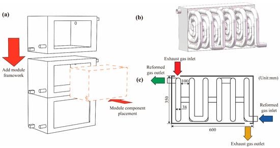
Figure 1.
Structural diagram of the methanol reforming hydrogen production reactor: (a) Schematic of modular assembly; (b) Three-dimensional structure; (c) Design dimensions.
Figure 1b,c illustrate the structural configuration and operating mechanism of the reforming heat exchange reaction chamber. As shown in Figure 1b, the reaction chamber adopts a nested design. The outer section serves as the flue gas heat inlet chamber, through which exhaust gas at a certain temperature is introduced. Inside this chamber, coiled circular tubes are arranged to form the methanol reforming reaction channels. Within each plane, the channels coil several loops before shifting axially to the next plane, where the coiling continues. This multilayer helical arrangement extends the gas flow path and significantly enhances heat transfer performance. Figure 1c presents the model dimensions and operating mode of the modular component, along with the energy and mass flow pathways during system operation. Heated air enters through the outer heating channel inlet, supplying thermal energy for the reaction process. The methanol–water mixture enters the inner spiral channels through the reactant inlet, where endothermic reactions generate hydrogen and carbon dioxide. This figure provides a clear visualization of the model’s spatial layout, key dimensions, and heat transfer pathways, forming the structural basis for subsequent numerical modeling and simulation analysis. The dimensions of the flue gas heat inlet chamber are 350 mm × 350 mm × 600 mm, and the diameter of the methanol reforming reaction tube is 38 mm.
To investigate the effect of reaction channel length on system performance, this study varied the spacing between adjacent circular tube coils, setting it to 100 mm, 75 mm, and 60 mm, which corresponded to methanol reforming channels with 6, 8, and 10 turns, respectively, as shown in Figure 2. These configurations were used to conduct subsequent simulation analyses and performance evaluations.
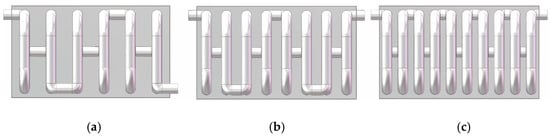
Figure 2.
Reactors with different channel spacings: (a) 100 mm; (b) 75 mm; (c) 60 mm.
2.2. Mathematical Model
This study employs a three-dimensional numerical model. The model used in this work is based on the following assumptions: (1) all gas species are treated as ideal gases; (2) body forces such as gravity are neglected; (3) gas-phase radiation is negligible compared with convection; and (4) the porous catalyst layer is assumed to be homogeneous and isotropic with uniform physical properties, while chemical reactions occur only within the catalyst region [24].
2.2.1. Continuity Equation
In these formulas,
represents the spatial coordinate of the fluid; represents the velocity vector.
2.2.2. Momentum Equation
In these formulas,
where denotes the momentum source term generated by the porous catalyst, which can be calculated using Equation (3).
- ;
- denotes the fluid density;
- denotes the permeability;
- denotes the directional inertial loss coefficients in the porous catalytic material;
- denotes the dynamic viscosity of the mixture.
The last source term in the momentum equation appears only when the fluid flows through the catalytic porous medium and becomes zero in the free-flow region. This term contributes to a significant pressure drop within the porous catalyst layer [24].
2.2.3. Energy Equation
In these formulas,
represents the effective thermal conductivity.
Usually, to account for the influence of the porous medium in the energy equation, it can be expressed as follows:
In these formulas,
- represents the thermal conductivity of the fluid within the porous medium
- represents the thermal conductivity of the solid phase.
2.2.4. Species Mass Fraction Equation
In these formulas,
- represents the mass fraction of the species;
- denotes the source term induced by chemical reactions within the catalyst, which is set to 0 in non-catalytic regions;
- represents the effective mass diffusion coefficient based on the Stefan–Maxwell equation [25].
To describe the effects of porosity and tortuosity on the porous catalyst, the effective mass diffusion coefficient is expressed as follows:
In these formulas,
- represents the mass diffusion coefficient of the gas mixture.
2.2.5. Chemical Reaction Equation
The reaction rate is calculated using the Arrhenius model [26], and the rate expression for methanol steam reforming is as follows:
In these formulas,
- represents the pre-exponential factor of the reaction;
- represents the activation energy corresponding to the reaction.
The relevant parameters are listed in Table 1.

Table 1.
Catalyst Parameters.
During the reaction process, the methanol conversion ratio can be calculated using Equation (10).
The studies listed in this table report the thermal properties, pore-structure characteristics, and reaction kinetics of Cu/Zn-based catalysts under medium–low temperature conditions of 200–300 °C, and their applicability and reliability within this temperature range have been validated through both experiments and numerical simulations. Given that the exhaust waste-heat temperatures simulated in this study also fall within the typical MSR operating window of 220–270 °C, adopting these parameters ensures the physical soundness of the porous-medium model in describing heat transfer, mass transport, and reaction kinetics, thereby enabling the numerical simulations to more closely represent real operating conditions.
2.3. Simulation Setup
In industrial boiler applications, low-temperature waste heat typically falls within the 200–300 °C range. For example, Lin et al. [31] reported measured data from a hot-blast furnace in a steel plant, showing that the exhaust-gas waste-heat temperature remained stable at 261–264 °C under typical operating conditions. Therefore, in the simulation process, the inlet of the hot air and the reforming reactant stream were defined using velocity inlet conditions, with the boundary settings summarized in Table 2.
Table 2.
Boundary Condition Settings.
In this study, the pressure-based SIMPLEC algorithm was employed to solve the momentum equations. To improve convergence and reduce computational time, the standard k–ε model was adopted as the turbulence model, and the standard wall function was used for wall treatment. The species transport model was applied to simulate both mass transport and chemical reactions. The reforming zone was defined as a porous medium, with heat transfer coupling established between the reforming and exhaust zones.
Spatial discretization was carried out using the least-squares cell-based method for gradient calculations. The pressure field was discretized using the standard scheme, while all other governing equations were discretized using the second-order upwind scheme. Convergence was considered achieved when all governing equation residuals approached steady-state conditions and both energy and mass balances were satisfied. The convergence criterion for the normalized residuals of all variables was set to be less than 1 × 10⁻⁶.
2.4. Simulation Validation
To evaluate the influence of mesh density on simulation accuracy and to determine the optimal mesh configuration, a grid independence verification was performed prior to the main simulations. Seven different mesh models were generated using the Fluent meshing software, Fluent 2023 R1, with total cell counts of 1,712,727; 1,927,263; 2,219,803; 2,585,201; 3,054,897; 3,667,500; and 4,471,844. Under identical boundary conditions and using the computational parameters listed in Table 2, the numerical results for different mesh densities were analyzed, as shown in Figure 3. When the mesh size exceeded 3,054,897 elements, further refinement produced negligible changes in the computed results. Therefore, a mesh size of 3,054,897 elements was selected for subsequent simulations in this study.
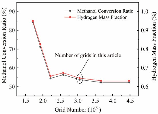
Figure 3.
Grid Independence Verification.
Figure 4 shows the mesh model consisting of 3,054,897 elements. The minimum surface mesh size was 2 mm, while the volume mesh was composed of unstructured polyhedral elements. Three boundary layers were added to each wall surface to improve near-wall resolution.
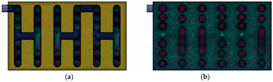
Figure 4.
Mesh used for simulation: (a) surface mesh section; (b) volume mesh section.
To ensure the validity of the model, the simulation results were compared with the experimental data reported by Fukahori et al. [30]. The microreactor described in their study was simulated using the numerical model developed in this work, with boundary conditions identical to those specified in the reference. The hydrogen production rate and methanol conversion ratio obtained from both the experiments and simulations are shown in Figure 5. The results indicate that, under different weight hourly space velocities (WHSV), the experimental and simulated data exhibit consistent trends, with deviations within ±3%. Therefore, the close agreement between the experimental and simulated results confirms the reliability of the model for subsequent simulations.
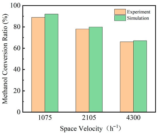
Figure 5.
Validation of Methanol Conversion Simulation Results.
3. Results and Discussion
3.1. Structural Influence on Coupled Heat and Mass Transfer Performance
Based on simulation calculations with different structural designs, the temperature field, pressure field, and methanol conversion distribution were obtained under three reaction channel spacings of 60 mm, 75 mm, and 100 mm. To facilitate analysis and comparison, this section presents a comparative discussion of the key performance parameters for the three configurations, aiming to elucidate the influence of channel spacing on the reaction process. To ensure consistency across different spacing conditions, the inlet temperature of the exhaust heat stream was uniformly set to 250 °C, and the reactant flow rate was varied from 0.4 g/s to 1.2 g/s.
3.1.1. Temperature Distribution
The temperature contour plots correspond to the vertical cross-section located at the geometric center of the model, as shown in Figure 6, which is used to illustrate the characteristic temperature field within a representative region of the reaction channel.
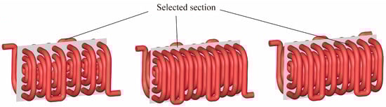
Figure 6.
Schematic Diagram of the Selected Model Cross-Section.
Figure 7 presents the variations in temperature distribution for channel spacings of 100 mm, 75 mm, and 60 mm, respectively, as the reactant inlet mass flow rate gradually increases from 0.4 g/s to 1.2 g/s.
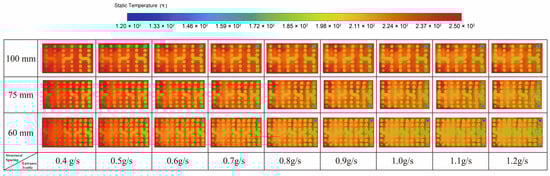
Figure 7.
Temperature Distribution for Different Structures.
Under different inlet flow-rate conditions, the temperature fields of the three structures exhibit similar trends, but their behavior is fundamentally governed by the coupling among flow residence time, wall heat-transfer intensity, and the rate of the endothermic reaction. As the reactant flow rate increases, the residence time of the gas inside the channel decreases, reducing the time available for heat transfer per unit volume and thus limiting the axial temperature rise. Meanwhile, a higher flow rate increases the instantaneous heat demand of the endothermic reaction, and when waste-heat supply is insufficient, the local thermal input cannot fully compensate for the reaction heat consumption.
From the perspective of a single structure, the temperature of the reactant gas gradually increases as it flows through the spiral channel, reflecting the typical characteristics of along-path heat absorption. Waste heat from the exhaust side continuously transfers through the tube wall into the reaction zone to compensate for the endothermic requirement of methanol steam reforming. In the initial reaction stage, the concentrations of methanol and steam are relatively high, the reaction rate is fast, and the heat absorption is substantial, resulting in a relatively slow temperature rise. As conversion increases, the reactant concentration gradually decreases, reaction kinetics weaken, and the overall heat demand of the system declines. At this point, the heat transferred through the wall is no longer heavily consumed, leading to a more pronounced temperature rise in the middle and downstream sections of the channel, where higher and more uniform temperatures are observed. Meanwhile, the continuous decline in exhaust-side temperature along the flow direction indicates that its thermal energy is constantly being extracted, forming a complete energy-transfer pathway in which low-grade waste heat from outside the tube is transferred through the wall to the reactant gas and ultimately drives the endothermic reaction.
The differences in heat-transfer performance among the three channel-spacing configurations mainly arise from the influence of geometric scale on heat-transfer area density and flow perturbation. Under identical operating conditions, the 60 mm structure exhibits the lowest temperature in the exhaust-heat chamber, indicating a higher effectiveness of waste-heat transfer to the reaction side. Given the same overall module dimensions, reducing the channel spacing increases the number of spiral turns and axial layers that can be accommodated within the housing, significantly extending the total length of the reaction channel and increasing the wall heat-transfer area per unit volume, thus providing greater potential thermal flux to the reaction zone. At the same time, the more compact spiral arrangement enhances exhaust-side flow recirculation and local disturbances, which improves the external convective heat-transfer coefficient. The longer reaction channel also increases the axial residence time of the fluid, allowing the reaction zone to operate under more uniform and stable thermal conditions. From the perspective of coupled heat transfer and reaction kinetics, the compact structure enhances heat-transfer area, wall heat flux, and effective residence time simultaneously, thereby establishing a more favorable match between thermal supply and reaction rate. As a result, it delivers superior overall reforming performance, demonstrating that channel spacing is a key geometric parameter governing both heat-transfer behavior and reaction efficiency.
3.1.2. Pressure Distribution
Figure 8 illustrates the variation in inlet pressure for the three channel spacing configurations under different reactant inlet mass flow rates. As the reactant flow rate increases progressively from 0.4 g/s to 1.2 g/s, the inlet pressure of all configurations rises significantly, indicating a positive correlation between system pressure drop and flow rate. This behavior is consistent with fundamental fluid transport principles, whereby an increase in flow rate enhances frictional resistance within the channel, thus requiring a higher pressure to sustain the flow. This mechanism is described by the Darcy–Weisbach equation and the Hagen–Poiseuille law, both of which indicate that pressure drop increases with rising flow velocity.
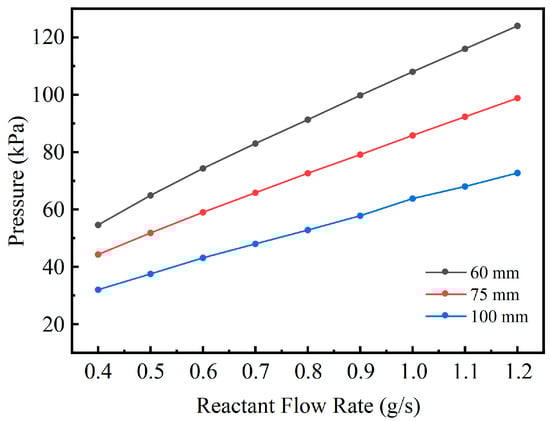
Figure 8.
Variation in Required Inlet Pressure with Reactant Flow Rate for Different Structures.
Under the same reactant flow-rate conditions, the three structures exhibit significant differences in inlet pressure, which can be fundamentally attributed to the influence of channel geometric scale on flow resistance and pressure-drop mechanisms. The 60 mm spacing structure shows the highest inlet pressure across the entire flow-rate range, followed by the 75 mm structure, while the 100 mm structure exhibits the lowest values. For example, at 1.0 g/s, the inlet pressures of the three structures are approximately 108, 85.8, and 63.8 kPa, respectively; when the flow rate increases to 1.2 g/s, these pressures rise to about 124, 98.8, and 72.7 kPa, respectively, further enlarging the pressure-drop differences among the structures. These results indicate that reducing the channel spacing leads to a more compact spiral flow passage, increasing both frictional losses along the curved channel and local flow losses, and thus requiring a higher driving pressure difference to maintain the same volumetric flow rate.
From a fluid dynamics perspective, this trend can be reasonably explained by the Darcy–Forchheimer model. Although the porous reforming channels of the three structures share identical microscopic permeability characteristics, reducing the channel spacing significantly lengthens the effective flow path within the porous region. For the same volumetric flow rate, the along-path pressure drop therefore increases with channel length. Meanwhile, at higher flow velocities, the inertial term in the Darcy–Forchheimer model becomes more dominant, causing the pressure drop to grow in a more nonlinear manner with increasing flow rate. The combination of these factors makes the 60 mm structure exhibit the most pronounced pressure-drop amplification under high-flow conditions, reflecting the enhanced flow resistance introduced by geometric compactness.
Figure 9 presents the pressure distribution contour plots for the structures with channel spacings of 100 mm, 75 mm, and 60 mm, respectively. These results further confirm the analysis described above. All three structures exhibit a typical along-channel pressure-drop pattern, characterized by the highest pressure at the inlet, a gradual decrease along the flow direction, and an outlet pressure approaching ambient conditions, indicating that the overall flow behavior is consistent across the different configurations. The differences lie primarily in the magnitude of the pressure drop rather than in the decay pattern, suggesting that channel spacing mainly affects the pressure-drop level rather than the qualitative pressure-distribution mode. In other words, geometric parameters influence the system’s energy dissipation intensity by modifying the effective flow-cross-sectional area and resistance coefficient, while the fundamental flow mechanisms remain unchanged.
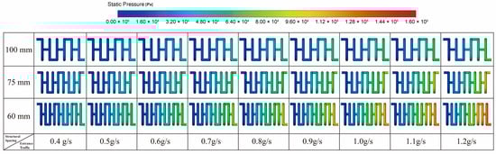
Figure 9.
Pressure Distribution for Different Structures.
From the perspective of overall system performance, variations in channel spacing directly influence heat-transfer intensity, flow resistance, and the coupling characteristics of the reforming reaction. A smaller spacing results in a more compact arrangement of reaction channels, providing a larger heat-transfer area within the same volume and maintaining a more favorable temperature field, thereby promoting the continuous progress of the endothermic reforming reaction. However, the compact structure also forces the fluid to travel through longer paths with higher resistance in the porous channels, causing the required pressure differential to increase noticeably with rising flow rate. In contrast, a larger spacing reduces flow resistance and lowers the required driving pressure, but weakens heat-transfer effectiveness, making it more difficult to sustain the thermal input necessary for the reforming process. Overall, channel spacing acts as a critical geometric parameter that governs the coupled relationship among heat supply, flow characteristics, and reaction kinetics. Different spacing configurations lead to distinct performance trade-offs between heat-transfer enhancement and flow-load requirements within the system.
Overall, the 60 mm spacing configuration exhibits the greatest pressure loss due to its more compact flow passages, followed by the 75 mm spacing structure, whereas the 100 mm spacing configuration demonstrates the lowest flow resistance and thus lower operating energy consumption. In engineering design, a comprehensive trade-off between heat transfer performance and flow resistance should be considered to achieve an optimal balance between system efficiency and energy consumption.
3.1.3. Methanol Conversion Ratio
As the reactant flow rate increases from 0.4 g/s to 1.2 g/s, the methanol conversion behavior of all three channel spacing configurations exhibits a consistent trend, as shown in Figure 10. With increasing flow rate, the methanol conversion ratio decreases continuously, while the mass fraction of unreacted methanol at the outlet gradually rises. This phenomenon is primarily attributed to the reduced residence time of the gas within the reaction channel at higher flow rates, leading to insufficient gas–solid contact and a lower overall reaction extent. In addition, a larger feed rate results in greater heat absorption demand, weakening the channel’s ability to maintain the reaction temperature. This further suppresses the endothermic reforming reaction, ultimately reducing the methanol conversion efficiency.
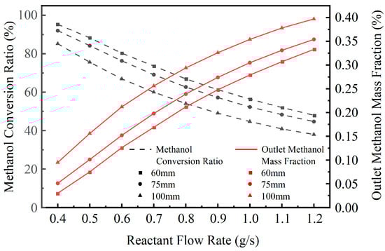
Figure 10.
Variation in Methanol Conversion Ratio and Outlet Methanol Mass Fraction with Reactant Flow Rate for Different Structures.
From a structural comparison perspective, the configuration with a 60 mm channel spacing maintains the highest methanol conversion ratio and the lowest outlet methanol mass fraction across the entire flow rate range, followed by the 75 mm spacing structure, while the 100 mm spacing structure shows the lowest performance. For instance, at a flow rate of 0.4 g/s, the methanol conversion ratios for the 60 mm, 75 mm, and 100 mm configurations are approximately 95.3%, 92.0%, and 85.2%, respectively. When the flow rate increases to 1.2 g/s, these values decrease to around 48.0%, 44.7%, and 38.0%, respectively. These results indicate that a smaller channel spacing enhances waste heat absorption and improves internal temperature uniformity, thereby promoting a higher reaction rate for the endothermic methanol steam reforming process.
Figure 11 illustrates the variation in hydrogen production rate for the three structural configurations under different feed flow rates. As the flow rate increases, the overall hydrogen mass fraction decreases, consistent with the trend observed in methanol conversion, further confirming that the combined effects of reduced residence time and increased heat demand lead to incomplete reactions. Among the three configurations, the 60 mm spacing structure consistently achieves the highest hydrogen production rate, followed by the 75 mm spacing structure, while the 100 mm spacing structure exhibits the lowest rate. This indicates that a more compact structure facilitates more effective heat coupling and better promotes the reforming reaction.
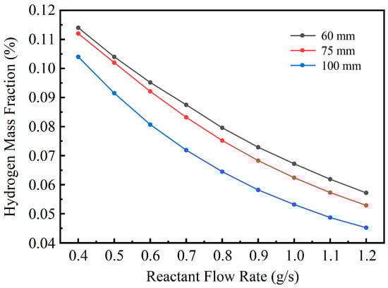
Figure 11.
Variation of Hydrogen Production Rate with Reactant Flow Rate for Different Structures.
To further elucidate the spatial characteristics of the reaction process, Figure 12 presents the methanol mass fraction distribution contours for models with channel spacings of 100 mm, 75 mm, and 60 mm, respectively. It can be observed that the methanol mass fraction gradually decreases along the flow direction, and the smaller spacing structures exhibit a wider methanol consumption region with more pronounced color transitions, indicating a more complete reforming reaction.
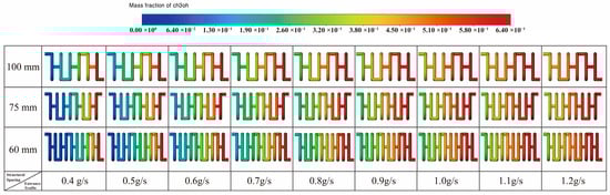
Figure 12.
Methanol Mass Fraction Distribution for Different Structures.
Correspondingly, Figure 13 illustrate the hydrogen mass fraction distribution within the three structures. The color transition from lower to higher values along the flow direction—from the channel inlet to the outlet—demonstrates the progressive accumulation of hydrogen as the reaction proceeds. Moreover, the smaller spacing structures show a more continuous and widespread hydrogen formation region, further reflecting their superior heat and mass transfer characteristics and higher reaction efficiency.
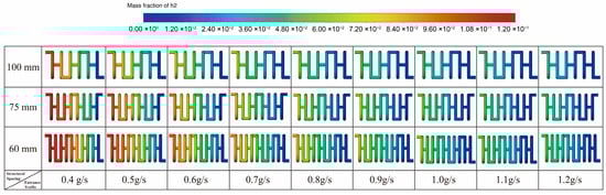
Figure 13.
Hydrogen Mass Fraction Distribution for Different Structures.
In summary, as the channel spacing decreases, the reactor exhibits a consistent improvement in both methanol conversion and hydrogen production performance. A more compact configuration enhances wall heat transfer and improves temperature maintenance within the reaction zone, thereby enabling a more complete methanol steam reforming reaction under identical operating conditions. These results indicate that appropriately reducing the channel spacing can significantly improve heat supply and reaction performance in modular reforming systems and thus promote higher hydrogen-generation efficiency.
3.2. Effects of Different Operating Parameters on Methanol Steam Reforming Performance
3.2.1. Methanol Conversion Rates Under Different Operating Conditions
Figure 14a–c illustrate the variation trends of methanol conversion ratios for the 100 mm, 75 mm, and 60 mm channel spacing structures under different exhaust heat temperatures. The exhaust gas temperature ranges from 220 °C to 270 °C, while the reactant flow rate increases gradually from 0.4 g/s to 1.2 g/s. The results indicate that the exhaust heat temperature exerts a significant influence on the methanol reforming reaction.
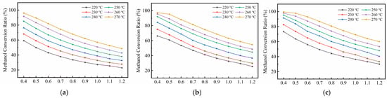
Figure 14.
Variation in Methanol Conversion Ratio with Reactant Flow Rate and Temperature for Different Structures: (a) 100 mm; (b) 75 mm; (c) 60 mm.
As the exhaust waste-heat temperature increases, the methanol conversion ratio of all three structures rises significantly, primarily due to the strong temperature sensitivity of the endothermic methanol steam reforming reaction. According to the Arrhenius model, the reaction rate increases with temperature; thus, within the 220–270 °C range, the reaction activity of the system is markedly enhanced, manifested as a continuous improvement in methanol conversion. Specifically, every 10 °C increase in temperature substantially strengthens the reaction driving force and reduces the apparent activation energy, thereby promoting the conversion of methanol molecules on the catalytic surface. Compared with the performance at 220 °C, all three structures show higher conversion levels at 270 °C, with the 60 mm structure exhibiting the most significant improvement. This indicates that the more compact spacing can better utilize the supplied heat under elevated temperatures, efficiently converting thermal energy into reaction-driving capability.
As the reactant flow rate increases, the methanol conversion ratio of all three structures shows an overall downward trend, which is fundamentally attributed to the combined effects of reduced residence time and increased heat demand per unit volume of reaction. At higher flow rates, the gas–catalyst contact time within the reaction channel becomes insufficient, limiting the complete conversion of methanol molecules. Meanwhile, the greater heat absorption required by the endothermic reaction makes it more difficult to maintain adequate local temperatures, thereby suppressing the reaction rate. Under higher waste-heat temperatures, the system gains stronger thermal compensation capacity, partially offsetting the adverse effects of increased flow rate and moderating the decline in conversion. For example, in the 100 mm structure, the conversion drops by approximately 39% when the flow rate increases from 0.4 g/s to 1.2 g/s at 270 °C, whereas the corresponding decrease at 220 °C is about 43%, indicating that higher waste-heat temperatures enhance thermal stability and improve the system’s adaptability to load fluctuations.
Differences among the three structures further reveal the influence of channel geometry on reaction efficiency. The 60 mm spacing consistently maintains the highest methanol conversion across all operating conditions. For instance, at 270 °C and 0.8 g/s, the conversion of the three structures are approximately 82%, 75%, and 70%, respectively. This result demonstrates that a more compact channel configuration shortens the heat-transfer path and increases the heat-transfer area per unit volume, effectively enhancing the transfer of wall heat flux into the reaction zone. At the same time, it improves the uniformity of the local temperature distribution, thereby creating a more favorable thermodynamic environment for the endothermic reaction.
3.2.2. Performance Comparison and Analysis with Other Studies
To further evaluate the heat-transfer and reaction performance of the proposed modular reactor structure for methanol steam reforming (MSR), several representative studies published in recent years were selected for comparison. A systematic analysis was conducted based on methanol conversion performance under different structural configurations and operating conditions.
Srivastava et al. developed a packed-bed counter-current heat-exchanger-type reactor and investigated the effects of reformate flow velocity on MSR performance. Under conditions with a reformate inlet temperature of 453 K and an exhaust inlet temperature of 673 K, the methanol conversion dropped markedly from approximately 75.3% to 38.2% as the flow velocity increased from 0.1 m/s to 0.3 m/s, indicating a pronounced decline in conversion efficiency [24]. Although the channel configuration and operating parameters of this study differ from those of the present work, a similar decreasing trend is observed here as the reactant mass flow rate rises from 0.4 g/s to 1.2 g/s. For instance, with an exhaust temperature of 260 °C the 100 mm channel-spacing structure exhibits a conversion decrease from 91.7% to 42.8%, suggesting consistency in the underlying mechanisms of residence-time limitation and heat-transfer constraints.
Wang et al. designed a rib-structured microreactor with a catalyst coating for exhaust-waste-heat-driven MSR and examined the influences of exhaust and reactant inlet conditions on reactor performance. Under the optimal operating conditions consisting of a reactant inlet temperature of 493 K, a reactant inlet velocity of 0.1 m/s, an exhaust inlet temperature of 773 K, and an exhaust inlet velocity of 1.1 m/s, the reactor achieved a methanol conversion of 99.4%, and the reactant inlet temperature was identified as the most critical factor affecting the MSR reaction [20]. Tang et al. further developed a shell-and-tube MSR system driven by engine exhaust waste heat, where baffle structures were introduced to enhance flow disturbance and improve heat-transfer performance. At an exhaust inlet temperature of 633 K and a feed rate of approximately 0.297 g/s, their system achieved a methanol conversion of 90.45% [21]. Under comparatively lower exhaust temperatures of 270 °C and a feed rate of 0.4 g/s, the modular reactor proposed in this study maintained a methanol conversion as high as 99.5% with the 60 mm channel-spacing structure.
In summary, although these studies differ in reactor configurations and boundary conditions, the compact modular design proposed in the present work demonstrates outstanding reaction-driving capability and broad adaptability under medium- and low-grade waste-heat conditions, providing an effective engineering pathway for distributed hydrogen production.
3.3. Statistical Significance Analysis of Structural Differences
To quantitatively assess the statistical significance of the influence exerted by different channel-spacing configurations on methanol conversion performance, and to eliminate the confounding effects associated with variations in exhaust waste-heat temperature and reactant inlet mass flow rate, a one-way analysis of covariance (ANCOVA) was carried out using all 162 cases. In this analysis, methanol conversion was designated as the dependent variable, while the channel spacing of 60 mm, 75 mm, and 100 mm was treated as the categorical independent factor. The waste-heat temperature within the range of 220 to 270 °C and the inlet mass flow rate within the range of 0.4 to 1.2 g/s were incorporated as continuous covariates to remove their linear contributions to the observed variations in conversion.
The ANCOVA was formulated as follows:
In this formulation, and represent the linear effects of temperature and flow rate, respectively, while denotes the main effect associated with channel spacing. The interaction tests for temperature–structure and flow–structure indicated that both interactions were statistically insignificant, with p values greater than 0.1. This outcome satisfies the assumption of homogeneous regression slopes, confirming that the linear adjustment of covariates is valid.
3.3.1. ANCOVA Statistical Results
As shown in Table 3, after controlling for the linear effects of temperature and flow rate, the channel-spacing configuration still exhibits a statistically significant influence, indicating that structural optimization contributes independently to the reaction performance.
Table 3.
Results of the One-Way ANCOVA.
The direction and magnitude of the covariate effects are consistent with the preceding process analysis: for every increase of 1 °C in temperature, the methanol conversion ratio increases by approximately 0.67% on average, whereas an increase of 0.1 g/s in inlet flow rate leads to an average decrease of about 5.7% in conversion. The coefficient of determination, with R2 approximately equal to 0.981, indicates that channel spacing, temperature, and flow rate collectively account for the vast majority of the variation in conversion.
3.3.2. Adjusted Conversion Ratio of the Structure
Because methanol conversion is influenced not only by channel spacing but also by systematic variations in waste-heat temperature and inlet mass flow rate, direct comparison of the raw conversion values across different structures would be susceptible to confounding bias arising from uneven distributions of operating conditions. To isolate the independent contribution of structural configuration to reaction performance, the present study employed the ANCOVA model to generate adjusted predictions of conversion for each structure under a unified operating condition, defined by a waste-heat temperature of 250 °C and an inlet mass flow rate of 0.8 g/s. The adjusted conversion values represent the expected conversion levels of the three structures under identical temperature and flow-rate conditions, thereby eliminating the influence of covariate differences. The results are presented in Table 4.
Table 4.
Adjusted Conversion Ratio.
The adjusted results indicate that channel spacing exerts a significant influence on methanol conversion. Under identical operating conditions, the structure with a spacing of 60 mm exhibits the highest adjusted conversion, followed by the 75 mm and 100 mm configurations. Pairwise comparisons show that the differences among the three structures are all highly significant. This demonstrates that even after controlling for the effects of temperature and flow rate, reducing the channel spacing still markedly enhances the effectiveness of the methanol steam reforming reaction. This conclusion is consistent with the earlier analyses of the flow and temperature fields and further confirms, from a statistical perspective, the advantage of smaller spacing in strengthening heat transfer.
3.4. Study on the Material and Energy Conversion Mechanisms Within the Reactor
To further elucidate the evolution patterns of the temperature and concentration fields inside the reactor, the structure with a 100 mm channel spacing was selected as a representative case for local cross-sectional flow field analysis. This configuration exhibits typical heat transfer and reaction characteristics, making it suitable for an in-depth examination of axial heat distribution, reactant consumption, and product formation within the reaction channels.
As shown in Figure 15, six representative cross-sections were selected along the axial direction of the reaction channel, each corresponding to the midsection of one spiral coil, sequentially numbered from the inlet to the outlet. The six selected cross-sections correspond to the mid-points of each spiral turn, where the geometric configuration and local heat-transfer conditions are most representative. These sections capture the typical flow and thermal characteristics within an individual turn, while their equal spacing along the axial direction allows the major evolutionary stages of the entire reaction process to be comprehensively covered. This arrangement effectively captures the complete evolution of the reaction process—from initial heating and temperature rise to reaction acceleration and stabilization in the later stage. By comparing the temperature and species mass fraction distributions at these cross-sections, the coupling mechanisms between heat transfer and reaction progression can be quantitatively revealed. This analysis provides valuable insight into how the thermal and concentration fields interact and evolve spatially within the reactor during the methanol reforming process.
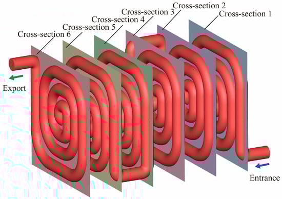
Figure 15.
Schematic Diagram of Cross-Sectional Contours for the 100 mm Channel Spacing Structure.
3.4.1. Temperature Field Analysis
To elucidate the axial evolution of the temperature field within the reactor, six equally spaced representative cross-sections were selected for comparative analysis, and their temperature distributions are shown in Figure 16. It can be observed that the overall temperature exhibits a clear axial increasing trend—namely, as the cross-sectional position moves farther from the inlet, the temperature within the channel gradually rises. This indicates that the reaction system continuously absorbs heat from the external exhaust heat inlet region along the flow direction, leading to a steady increase and eventual stabilization of the reaction temperature. This behavior aligns with the thermal characteristics of the endothermic methanol steam reforming reaction, confirming that under this structural configuration, the reaction channel maintains an effective and sustained heat transfer capability.
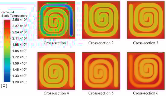
Figure 16.
Temperature Distribution at Cross-Sections for the 100 mm Channel Spacing Structure.
From the perspective of radial distribution, all cross-sections exhibit a temperature profile that decreases gradually from the tube wall toward the channel center, indicating that the wall temperature is consistently higher than that of the central region. This distribution arises because the exhaust waste heat is transferred through the tube wall, allowing the near-wall region to receive the highest thermal flux, while the temperature rise in the channel center is governed primarily by internal convection and molecular diffusion. In the initial stage of the reaction, the methanol steam reforming rate is relatively high, and the heat absorption in the central region is more intense, leading to a more pronounced temperature difference between the wall and the core. As the fluid progresses along the channel, the reactant concentration gradually decreases and the intensity of heat absorption diminishes. Consequently, the temperature in the central region is no longer significantly suppressed, and the heat supplied through the wall diffuses more effectively toward the interior. This results in a gradual reduction in radial temperature gradients and a progressively smoother temperature distribution across the cross-section.
In addition, the inlet cross-section exhibits the lowest temperature, with some areas still close to the initial feed temperature. In contrast, by the final cross-section, the temperature field becomes nearly uniform and approaches the level of the external heating source. This observation further confirms that the 100 mm spacing structure effectively ensures sufficient heat input to the reactants within the channel, enabling a steady temperature rise and creating favorable thermal conditions for the sustained progression of the reforming reaction.
3.4.2. Methanol Concentration Field Analysis
Figure 17 presents the methanol mass fraction distributions across six representative cross-sections along the reaction channel of the 100 mm spacing structure. It is evident that the methanol mass fraction decreases progressively along the flow direction, exhibiting a typical axial declining trend. At the inlet cross-section (Cross-section 1), the methanol mass fraction remains relatively high, with the color distribution concentrated in the high-value region, indicating that the reactant has not yet undergone significant conversion. As the flow proceeds downstream toward the outlet, the methanol mass fraction decreases gradually. Between Cross-sections 3 and 4, the color distribution clearly shifts toward lower values, suggesting that the reforming reaction is actively progressing and methanol is being substantially consumed. By Cross-section 6, the methanol mass fraction within the channel further declines, with the distribution concentrated in the lowest color range, signifying that most of the methanol has been converted and the system has nearly reached the terminal stage of the reaction.
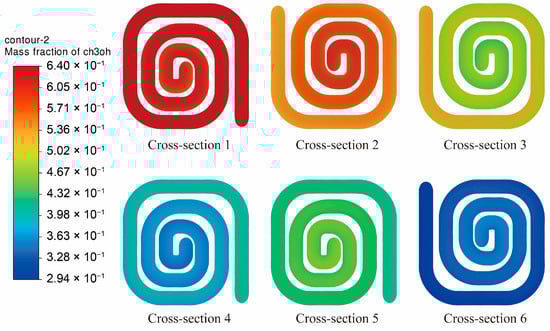
Figure 17.
Methanol Mass Fraction Distribution at Cross-Sections for the 100 mm Channel Spacing Structure.
In the inlet region, the reaction temperature is relatively low and the reforming process has not yet fully developed, resulting in a slow consumption rate of methanol. In the middle and downstream sections of the channel, however, the temperature increases and the reaction rate constant rises significantly, leading to an accelerated catalytic reaction. Consequently, the methanol concentration decreases rapidly, demonstrating the strong enhancing effect of temperature on the reaction kinetics.
Moreover, the methanol concentration field within each cross-section exhibits an overall uniform radial distribution, with no evident local concentration retention or accumulation, indicating that the structure provides favorable mass-transfer uniformity. The secondary flow and perturbation effects generated by the spiral channel configuration strengthen the contact efficiency between the reactant stream and the catalytic wall, reduce the thickness of the concentration boundary layer, and thereby effectively promote the diffusion of reactants toward the catalytic surface. Combined with the preceding temperature-field analysis, it becomes clear that the spatial variations in temperature rise and concentration decline proceed in a synchronized manner. This reveals a strong coupling between the temperature and concentration fields within the reaction zone, whereby the increase in temperature directly accelerates the reaction rate and consequently enhances the consumption of methanol.
Overall, the methanol conversion process within this configuration progresses steadily along the flow direction. The coordination between heat and mass transfer enhances the continuous consumption of methanol and achieves high reaction efficiency. These results provide important insights into the kinetic behavior of the system and the underlying mechanisms governing energy–matter coupling during the methanol reforming process.
4. Conclusions
This study proposed a small-scale modular methanol reforming hydrogen production system based on exhaust heat recovery and conducted a three-dimensional numerical analysis focusing on the heat transfer and reaction behaviors within the reactor. The results show that the modular structure is compact and flexible in layout, offering strong potential for coupling with waste heat from small industrial boilers. Under typical exhaust heat temperature conditions, the system can continuously absorb and utilize the recovered thermal energy to drive the endothermic reforming reaction, resulting in high methanol conversion efficiency and demonstrating the practical feasibility of waste-heat-driven MSR.
Both the feed flow rate and exhaust heat temperature have a significant impact on reaction performance. Higher exhaust heat temperatures enhance the reaction, while increased feed rates can improve hydrogen production but tend to suppress single-pass conversion efficiency. Overall, this study provides a valuable design concept and analytical approach for distributed hydrogen energy supply and industrial waste heat utilization. Future work will focus on optimizing module coupling configurations, improving heat exchange structures, and developing control strategies under dynamic operating conditions to further verify the engineering applicability of the system and support its practical implementation.
Author Contributions
Conceptualization, Y.C.; methodology, Y.C.; software, Y.J. (Yihan Jiang) and D.X.; validation, Y.J. (Yihan Jiang) and D.X.; formal analysis, J.L.; investigation, Y.J. (Yihan Jiang); resources, Y.C.; data curation, Y.J. (Yangyang Ji); writing—original draft preparation, Y.J. (Yihan Jiang); writing—review and editing, Y.C., Y.J. (Yihan Jiang) and X.L.; visualization, Y.J. (Yangyang Ji); supervision, Y.C. All authors have read and agreed to the published version of the manuscript.
Funding
This work was supported by the Department of Education of Hubei Province (grant number Q20231401), and Hubei University of Technology (grant number XJ2023002401).
Institutional Review Board Statement
Not applicable.
Informed Consent Statement
Not applicable.
Data Availability Statement
The original contributions presented in this study are included in the article. Further inquiries can be directed to the corresponding author.
Conflicts of Interest
The authors declare no conflict of interest.
References
- Qureshi, F.; Yusuf, M.; Pasha, A.A.; Khan, H.W.; Imteyaz, B.; Irshad, K. Sustainable and Energy Efficient Hydrogen Production via Glycerol Reforming Techniques: A Review. Int. J. Hydrogen Energy 2022, 47, 41397–41420. [Google Scholar] [CrossRef]
- Zeighami, A.; Kern, J.; Yates, A.J.; Weber, P.; Bruno, A.A. U.S. West Coast Droughts and Heat Waves Exacerbate Pollution Inequality and Can Evade Emission Control Policies. Nat. Commun. 2023, 14, 1415. [Google Scholar] [CrossRef]
- Wabnitz, K.-J.; Guzman, V.; Haldane, V.; Ante-Testard, P.A.; Shan, Y.; Blom, I.M. Planetary Health: Young Academics Ask Universities to Act. Lancet Planet Health 2020, 4, e257–e258. [Google Scholar] [CrossRef]
- Zhang, C.; Wang, J. Preparation of P-doped Ni Catalyst Using Deep Eutectic Solvents and Its Excellent Hydrogen Evolution Performance in Water Splitting. ChemistryOpen 2025, 14, e202500023. [Google Scholar] [CrossRef] [PubMed]
- Rasul, M.G.; Hazrat, M.A.; Sattar, M.A.; Jahirul, M.I.; Shearer, M.J. The Future of Hydrogen: Challenges on Production, Storage and Applications. Energy Convers. Manag. 2022, 272, 116326. [Google Scholar] [CrossRef]
- Ji, M.; Wang, J. Review and Comparison of Various Hydrogen Production Methods Based on Costs and Life Cycle Impact Assessment Indicators. Int. J. Hydrogen Energy 2021, 46, 38612–38635. [Google Scholar] [CrossRef]
- Kovač, A.; Paranos, M.; Marciuš, D. Hydrogen in Energy Transition: A Review. Int. J. Hydrogen Energy 2021, 46, 10016–10035. [Google Scholar] [CrossRef]
- Abe, J.O.; Popoola, A.P.I.; Ajenifuja, E.; Popoola, O.M. Hydrogen Energy, Economy and Storage: Review and Recommendation. Int. J. Hydrogen Energy 2019, 44, 15072–15086. [Google Scholar] [CrossRef]
- Faye, O.; Szpunar, J.; Eduok, U. A Critical Review on the Current Technologies for the Generation, Storage, and Transportation of Hydrogen. Int. J. Hydrogen Energy 2022, 47, 13771–13802. [Google Scholar] [CrossRef]
- Achomo, M.A.; Kumar, A.; Peela, N.R.; Muthukumar, P. Hydrogen Production from Steam Reforming of Methanol: A Comprehensive Review on Thermodynamics, Catalysts, Reactors, and Kinetic Studies. Int. J. Hydrogen Energy 2024, 58, 1640–1672. [Google Scholar] [CrossRef]
- Mei, D.; Qiu, X.; Liu, H.; Wu, Q.; Yu, S.; Xu, L.; Zuo, T.; Wang, Y. Progress on Methanol Reforming Technologies for Highly Efficient Hydrogen Production and Applications. Int. J. Hydrogen Energy 2022, 47, 35757–35777. [Google Scholar] [CrossRef]
- Iulianelli, A.; Ribeirinha, P.; Mendes, A.; Basile, A. Methanol Steam Reforming for Hydrogen Generation via Conventional and Membrane Reactors: A Review. Renew. Sustain. Energy Rev. 2014, 29, 355–368. [Google Scholar] [CrossRef]
- Holladay, J.D.; Hu, J.; King, D.L.; Wang, Y. An Overview of Hydrogen Production Technologies. Catal. Today 2009, 139, 244–260. [Google Scholar] [CrossRef]
- Peppley, B.A.; Amphlett, J.C.; Kearns, L.M.; Mann, R.F. Methanol–Steam Reforming on Cu/ZnO/Al2O3. Part 1: The Reaction Network. Appl. Catal. A Gen. 1999, 179, 21–29. [Google Scholar] [CrossRef]
- Papapetrou, M.; Kosmadakis, G.; Cipollina, A.; La Commare, U.; Micale, G. Industrial Waste Heat: Estimation of the Technically Available Resource in the EU per Industrial Sector, Temperature Level and Country. Appl. Therm. Eng. 2018, 138, 207–216. [Google Scholar] [CrossRef]
- Roy, J.P.; Mishra, M.K.; Misra, A. Parametric Optimization and Performance Analysis of a Waste Heat Recovery System Using Organic Rankine Cycle. Energy 2010, 35, 5049–5062. [Google Scholar] [CrossRef]
- Toklu, E.; Coskun Avci, A.; Kaygusuz, K.; Gur, M. A Research on Hydrogen Production from Industrial Waste Heat by Thermal Water Splitting. Int. J. Hydrogen Energy 2016, 41, 10071–10079. [Google Scholar] [CrossRef]
- Kang, J.; Song, Y.; Kim, T.; Kim, S. Recent Trends in the Development of Reactor Systems for Hydrogen Production via Methanol Steam Reforming. Int. J. Hydrogen Energy 2022, 47, 3587–3610. [Google Scholar] [CrossRef]
- Forman, C.; Muritala, I.K.; Pardemann, R.; Meyer, B. Estimating the Global Waste Heat Potential. Renew. Sustain. Energy Rev. 2016, 57, 1568–1579. [Google Scholar] [CrossRef]
- Wang, G.; Wang, F.; Chen, B. Performance Study on Methanol Steam Reforming Rib Micro-Reactor with Waste Heat Recovery. Energies 2020, 13, 1564. [Google Scholar] [CrossRef]
- Tang, Y.; Wang, Y.; Long, W.; Xiao, G.; Wang, Y.; Li, W. Analysis and Enhancement of Methanol Reformer Performance for Online Reforming Based on Waste Heat Recovery of Methanol-Diesel Dual Direct Injection Engine. Energy 2023, 283, 129098. [Google Scholar] [CrossRef]
- Yao, L.; Wang, F.; Wang, L.; Wang, G. Transport Enhancement Study on Small-Scale Methanol Steam Reforming Reactor with Waste Heat Recovery for Hydrogen Production. Energy 2019, 175, 986–997. [Google Scholar] [CrossRef]
- Wang, R.; Ma, T.; Ding, R.; Liu, W.; Sun, D. Catalyst, Reactor, and Purification Technology in Methanol Steam Reforming for Hydrogen Production: A Review. Catalysts 2025, 15, 802. [Google Scholar] [CrossRef]
- Srivastava, A.; Kumar, P.; Dhar, A. A Numerical Study on Methanol Steam Reforming Reactor Utilizing Engine Exhaust Heat for Hydrogen Generation. Int. J. Hydrogen Energy 2021, 46, 38073–38088. [Google Scholar] [CrossRef]
- Karim, A.; Bravo, J.; Gorm, D.; Conant, T.; Datye, A. Comparison of Wall-Coated and Packed-Bed Reactors for Steam Reforming of Methanol. Catal. Today 2005, 110, 86–91. [Google Scholar] [CrossRef]
- Purnama, H.; Ressler, T.; Jentoft, R.E.; Soerijanto, H.; Schlögl, R.; Schomäcker, R. CO Formation/Selectivity for Steam Reforming of Methanol with a Commercial CuO/ZnO/Al2O3. Appl. Catal. A Gen. 2004, 259, 83–94. [Google Scholar] [CrossRef]
- Karim, A.; Bravo, J.; Datye, A. Nonisothermality in Packed Bed Reactors for Steam Reforming of Methanol. Appl. Catal. A Gen. 2005, 282, 101–109. [Google Scholar] [CrossRef]
- Agrell, J.; Birgersson, H.; Boutonnet, M. Steam Reforming of Methanol over a Cu/ZnO/Al2O3 Catalyst: A Kinetic Analysis and Strategies for Suppression of CO Formation. J. Power Sources 2002, 106, 249–257. [Google Scholar] [CrossRef]
- Perng, S.-W.; Horng, R.-F.; Wu, H.-W. Effect of a Diffuser on Performance Enhancement of a Cylindrical Methanol Steam Reformer by Computational Fluid Dynamic Analysis. Appl. Energy 2017, 206, 312–328. [Google Scholar] [CrossRef]
- Fukahori, S.; Koga, H.; Kitaoka, T.; Nakamura, M.; Wariishi, H. Steam Reforming Behavior of Methanol Using Paper-Structured Catalysts: Experimental and Computational Fluid Dynamic Analysis. Int. J. Hydrogen Energy 2008, 33, 1661–1670. [Google Scholar] [CrossRef]
- Lin, P.-H.; Wang, P.-H.; Chen, H.-T.; Chung, W.-L. Efficiency Improvement of the Hot Blast Generating System by Waste Heat Recovery. In Energy and Sustainability, Proceedings of the International Conference on Energy and Sustainability, The New Forest, UK, 14–16 June 2007; WIT Press: Southampton, UK, 2007; pp. 113–121. [Google Scholar]
Disclaimer/Publisher’s Note: The statements, opinions and data contained in all publications are solely those of the individual author(s) and contributor(s) and not of MDPI and/or the editor(s). MDPI and/or the editor(s) disclaim responsibility for any injury to people or property resulting from any ideas, methods, instructions or products referred to in the content. |
© 2025 by the authors. Licensee MDPI, Basel, Switzerland. This article is an open access article distributed under the terms and conditions of the Creative Commons Attribution (CC BY) license (https://creativecommons.org/licenses/by/4.0/).