Article

Experimental Study on the Mechanics and Impact Resistance of Multiphase Lightweight Aggregate Concrete

1
School of Civil Engineering, Architecture and Environment, Hubei University of Technology, Wuhan 430068, China
2
China Construction Third Bureau First Engineering Co., Ltd., Wuhan 430040, China
3
China Construction Shenzhen Decoration Co., Ltd., Wuhan 430068, China
*
Author to whom correspondence should be addressed.
Sustainability 2022, 14(15), 9606; https://doi.org/10.3390/su14159606
Submission received: 21 July 2022 / Revised: 2 August 2022 / Accepted: 3 August 2022 / Published: 4 August 2022

Abstract

:
Multiphase lightweight aggregate concrete (MLAC) is a green composite building material prepared by replacing part of the crushed stone in concrete with other coarse aggregates to save construction ore resources. For the best MLAC performance in this paper, four kinds of coarse aggregate—coal gangue ceramsite, fly ash ceramsite, pumice and coral—were used in different dosages (10%, 20%, 30% and 40%) of the total coarse aggregate replacement. Mechanical property and impact resistance tests on each MLAC group showed that, when coal gangue ceramsite was 20%, the mechanical properties and impact resistance of concrete were the best. The compressive, flexural and splitting tensile strength and impact energy dissipation increased by 29.25, 19.93, 13.89 and 8.2%, respectively, compared with benchmark concrete. The impact loss evolution equation established by the two-parameter Weibull distribution model effectively describes the damage evolution process of MLAC under dynamic loading. The results of a comprehensive performance evaluation of four multiphase light aggregate concretes are coal gangue ceramsite concrete (CGC) > fly ash ceramsite concrete (FAC) > coral aggregate concrete (CC) > pumice aggregate concrete (PC).

1. Introduction

Due to technological innovation and the impact on resources, the construction industry must become sustainable [1]. As the world’s major construction materials, concrete is widely used in buildings, roads, bridges, and ocean engineering. The need to produce huge amounts of concrete every year entails a large amount of sand and stone mining, which causes environmental damage and an aggregate shortage. Coal gangue is the waste product of coal mining and washing, and the world produces 350 million tons every year [2]. At the same time, the world annually produces 78 million tons of industrial fly ash waste [3]. Using this constantly generated waste to replace coarse aggregates to produce multiphase lightweight aggregate concrete (MLAC) maximizes the use of recycled materials, meets the need for sustainable construction [4] and reduces costs [5]. MLAC provides a sustainable method for waste recycling and utilization and plays an important role in sustainability [6].
Gangue can be ground into powder as cementitious material or additive, or it can be prepared as aggregates. Ashfaq et al. [7] showed that coal gangue has good earthwork performance, and its use in earthwork projects reduces carbon emissions. Gao et al. [8] studied coal gangue as a coarse aggregate in the production of green concrete and found that increasing the replacement rate reduced the mechanical properties of coal gangue concrete, so it is not advisable to use a too-high or too-low concrete design grade. Kockal et al. [9] studied the mechanical properties and durability of fly ash light aggregate concrete. As a complete replacement for normal weight coarse aggregate, it resulted in a reduction in compressive and splitting tensile strength from 62.9 MPa and 5.1 MPa to 42.3 MPa and 3.7 MPa, respectively. Jayabharath and Kesavan et al. [10] found that the impact resistance of concrete produced from conventional aggregates was higher than that of concrete produced from fly ash aggregates. Dahim et al. [11] found that after reducing the size of fly ash from the micron to the nanoscale by ball milling, the concrete had a higher compressive strength compared to concrete containing conventional micro fly ash. Hemalatha et al. [12] showed that fly ash has been extensively studied as a replacement for cement since the end of the 20th century, and Hasan et al. [13] investigated the impact resistance of concrete produced from fly ash. The results showed that different types of cold consolidated fly ash aggregate slightly reduce compressive and splitting tensile strength and impact resistance. However, replacing 8–16 mm aggregates with cold consolidated fly ash improved all aspects of concrete performance.
Pumice, a natural material of volcanic origin, has been used as an aggregate in the production of lightweight concrete in many countries. Worldwide, pumice is relatively abundant. Turkey alone accounts for about 40% of the world’s known pumice reserves (18 billion m3) [14,15]. Hatice et al. [16] used acidic pumice to make pervious concrete and found that its strength compared to crushed stone decreased because of the fragility of the pumice. Hossain et al. [17] studied the mechanical properties and durability of lightweight volcanic pumice concrete, but experimental results showed that it had low compatibility as an alternative to common coarse aggregate. Kurt et al. [18] investigated the effect of fly ash on the self-compactness of pumice light aggregate concrete. The experimental results of 20, 40, 60, 80 and 100% pumice as a natural aggregate decreased the flow diameter of SCC concrete and material by 5, 6, 9 and 19%, respectively. Amel et al. [19] found that concrete with a dry density of 1430–1690 kg/m3 could be obtained by using pumice as a coarse aggregate. Bakis [20] studied the effect of dune sand and pumice on the mechanical properties of lightweight concrete, and the results showed that pumice powder can be used as a binder for road pavement in an optimum binder ratio of 30% pumice and 20% lime.
As the exploitation of marine resources has become more and more important, the demand for concrete for island construction projects has become stronger. If the island is far away from the mainland, the construction cost is serious. Without damaging the environment, using coral to replace part of the coarse aggregate can effectively reduce the cost and shorten the construction time [21]. Therefore, it is feasible to use coral as an aggregate for mixing concrete. Many researchers have studied the properties of coral concrete. Arumugam et al. [22] found that the strength of normal concrete is higher than that of all-coral aggregate concrete at the same water–cement ratio. Kakooei et al. [23] found that the compressive strength of coral concrete increased with an increase in polypropylene fiber admixture, and the compressive strength was maximized when the admixture was 2 kg/m3. Niu et al. [24] found that the incorporation of 0.05% basalt fibers improved the mechanical properties of coral concrete the most by 9.87% and 1.36% in compressive and splitting compressive strength, respectively, at 28 days. Rao et al. [25] found that PVA fibers effectively enhanced the mechanical properties of coral concrete with an optimum admixture rate of 2–3 kg/m3. Cheng [26] found that coral sand concrete had better carbonation depth and capillary water absorption, compared to river sand concrete.
In the current construction industry, most aggregates need to be mined, which may lead to severe damage to mountains and forests [27]. Therefore, the use of industrial waste and abandoned coral to replace part of the coarse aggregate not only reduces industrial waste, but also reduces the damage caused by aggregate extraction [28]. Impact resistance is one of the important characteristics of concrete. Many concrete members are subjected to dynamic loads, such as pile foundations, bridge structures, dams and offshore platforms. These human and natural factors have a serious impact on the safe use of concrete structures, so how to ensure the safety of concrete members under dynamic load is something researchers need to solve. Based on these problems, four kinds of lightweight aggregate—coal gangue ceramsite, fly ash ceramsite, pumice and coral—were selected to replace part of the coarse aggregate. The change in concrete performance after their addition was comprehensively evaluated by mechanical tests and impact resistance.

2. Materials and Methods

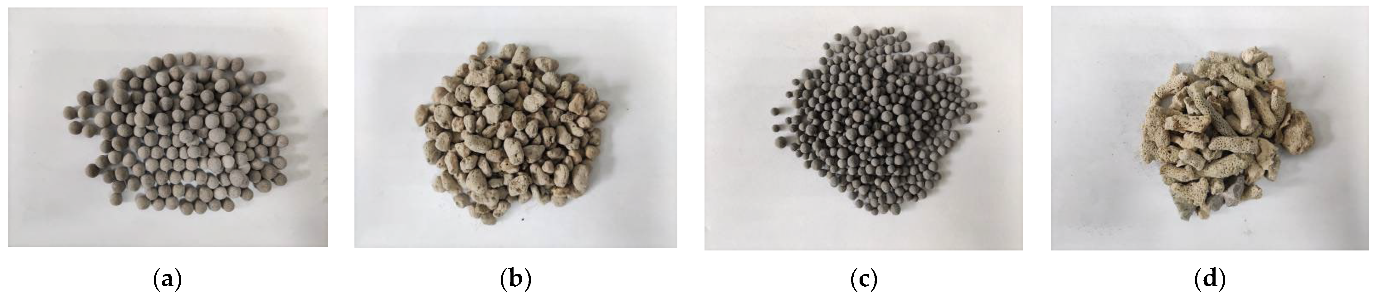
2.1. Test Materials and Mix Design

The cement was P.O42.5 ordinary silicate produced by China Huaxin Cement Joint Stock Company, and the fly ash was Grade I produced by Henan Hengyuan New Material Corporation. As shown in Figure 1, the coarse aggregate was continuous grading crushed stone, coal gangue and fly ash ceramsite, and pumice and coral aggregate. The particle size was controlled at 5–15 mm. The fine aggregate was natural river sand with a fineness modulus of 2.92 mm, water content 2.51% and water absorption 7.58%. The water reducing agent was a polycarboxylic acid high-performance water-reducing agent with a water reduction rate of 35%. The physical properties of lightweight aggregate are shown in Table 1.
The reference strength of concrete is C40. To study the influence of different lightweight aggregates on the mechanical properties and durability of concrete, the coarse aggregate was replaced with coal gangue ceramsite, fly ash ceramsite, pumice and coral, and the replacement rates were 10%, 20%, 30% and 40%. The mix design of concrete is shown in Table 2.

2.2. Test Methods

Because of the porosity and water absorption of lightweight aggregate, the water absorption and water return characteristics occurred during the preparation of the concrete, so the coal gangue ceramsite, fly ash ceramsite, pumice and coral had to be pre-wetted. After the specimens were soaked in water for 24 h, rinsed and dried, they were prepared in a HJS-60 double-horizontal axis concrete mixer. The compressive strength test specimen specification was 100 × 100 × 100 mm; the flexural strength test specimen specification was 100 × 100 × 400 mm; the splitting tensile strength test specimen specification was 100 × 100 × 100 mm; and the drop hammer impact test specimen specification was a Φ150 × 63 mm cylinder. All specimens had to be maintained for 28 days in an environment at a temperature of 20 ± 2 °C and relative humidity of more than 95% before the studies could be carried out. The design strength of concrete in this test was C40, so according to the specification, the loading speed in the compressive test was 0.5 MPa/s. In the flexural and splitting tests, the loading speed was 0.05 MPa/s. The relevant parameters were set; the test was conducted, and the relevant data were recorded.
The impact test was performed using the falling hammer method recommended by the American Concrete Institute: ACI544 standard [29]. It has the advantages of simple operation and low test requirements. The apparatus was a CECS13-2009 concrete falling hammer impact testing machine. Before the test, the cylinder specimen was placed in the specified test area, and a steel ball was placed in the center of the specimen. The drop hammer was aligned with the steel ball through an infrared device. An electromagnetic relay was used to carry out the test and record the number of drop hammer impacts. The first visible crack is regarded as the initial crack state and was recorded as initial crack number N1. When the specimen contacted any three of the four baffles, it was regarded as the damage state and recorded as final crack number N2.

3. Experimental Design and Results

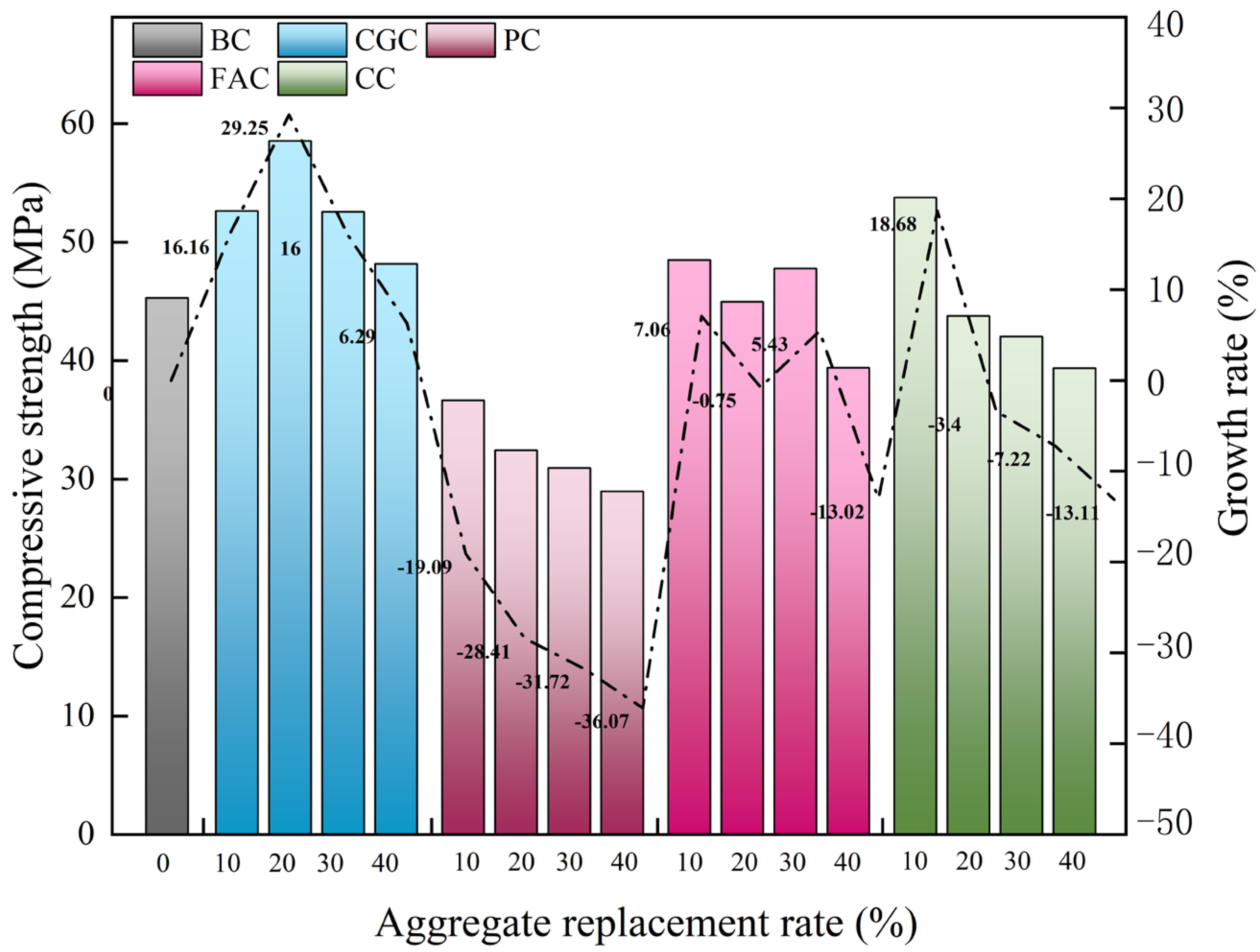
3.1. Cubic Compressive Strength Test

As shown in Figure 2, when coal gangue ceramsite content increased, the compressive strength of CGC increased then decreased. When the content of coal gangue was 20%, the compressive strength of CGC reached the optimal value, and the compressive strength increased by 29.25%. With increased fly ash ceramsite content, the FAC compressive strength increased, decreased, increased again and finally decreased. When the content of fly ash ceramsite was 10%, the FAC compressive strength increased by 7.06%. When the content was 40%, the FAC compressive strength decreased by 13.02%. When the coral aggregate content was 10%, the CC compressive strength increased by 18.68%. When the content was 40%, the CC compressive strength decreased by 13.11%. With increased pumice aggregate, the CC compressive strength decreased. When the pumice aggregate was 40%, the CC compressive strength decreased by 36.07%.

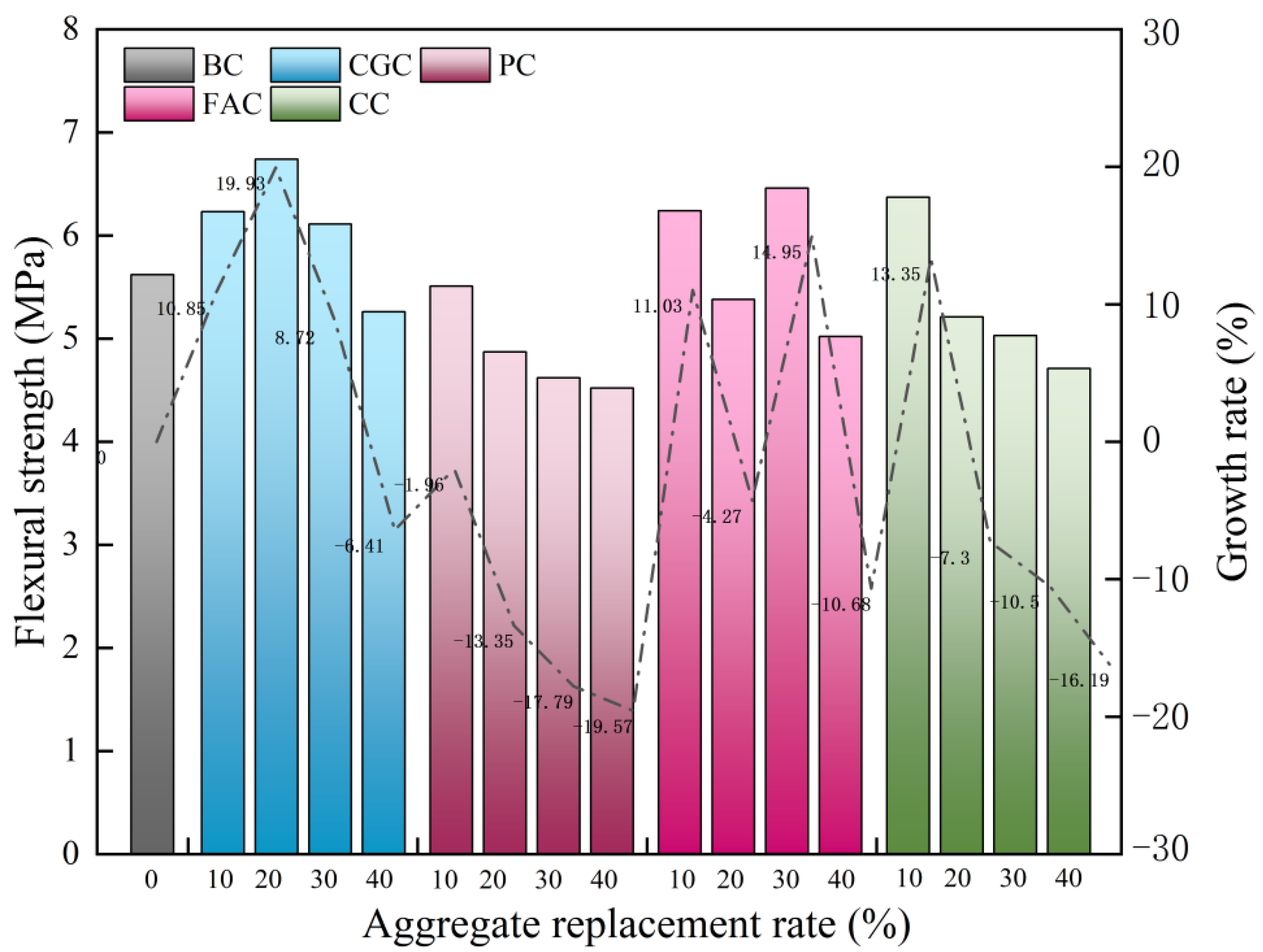
3.2. Flexural Strength Test

As shown in Figure 3, with increased coal gangue ceramsite, the flexural strength of CGC increased then decreased. When coal gangue ceramsite was 20%, the CGC flexural strength reached optimal value, and the flexural strength increased by 19.93%. When the coal gangue ceramsite was greater than 20%, the CGC flexural strength began to decrease. When it was 40%, the CGC flexural strength of decreased by 6.41%. With increased fly ash ceramsite, the FAC increased, decreased, and finally increased again. When the content was 30%, the FAC flexural strength was the strongest, and flexural strength increased by 14.96%. When fly ash ceramsite was 40%, the FAC flexural strength decreased by 10.58%. With the increased coral aggregate content, the CC increased then decreased. When the dosage was 10%, the flexural strength of CC increased by 13.35%. The PC decreased with the increased pumice aggregate. When the pumice content was 40%, the PC decreased by 19.57%.

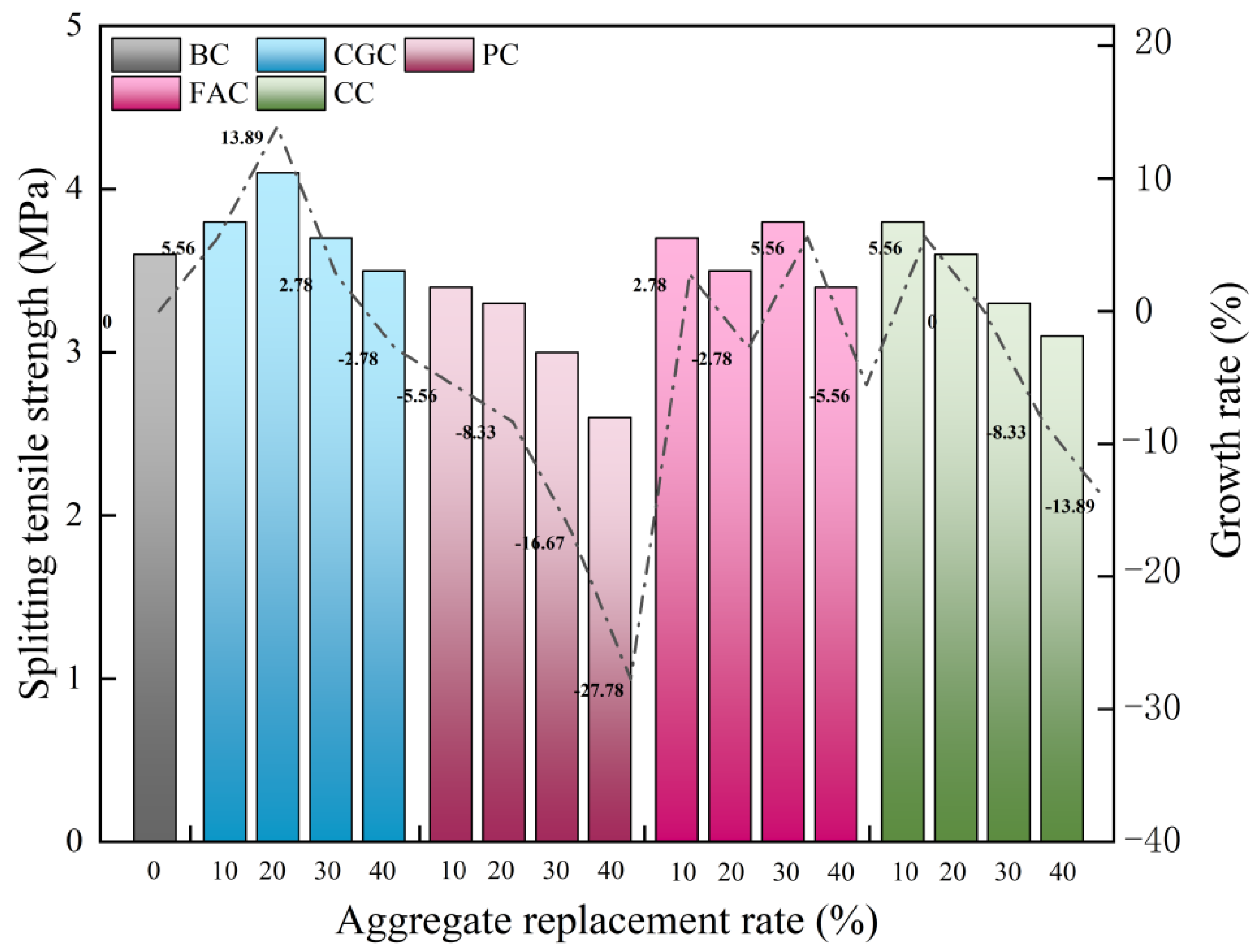
3.3. Splitting Tensile Strength

As shown in Figure 4, with increased coal gangue ceramsite, the CGC splitting tensile strength increased then decreased. When it was 20%, the CGC splitting tensile strength was the largest, increasing by 13.89%. With increased fly ash ceramsite, the FAC splitting tensile strength increased, decreased, increased again and finally decreased. When fly ash ceramsite was 30%, the splitting tensile strength reached maximum value, which was an increase of 5.56%. With increased coral aggregate, the CC increased then decreased. When it was 10%, the CC splitting tensile strength was the largest, with an increase of 5.56%. With the increase of pumice aggregate, PC splitting tensile strength decreased. When the pumice aggregate was 40%, the PC splitting tensile strength decreased by 27.78%.

3.4. Internal Mechanism Analysis of MLAC

The micropore structure inside the ceramsite functions like a micropump and reservoir. Under capillary action, ceramsite migrates water in the concrete, which gives it the characteristics of absorbing and returning water. It can effectively improve the performance of the interfacial transition zone (ITZ), increase the bonding force between the ceramsite and mortar interface, and make the structure of concrete interfacial zone closer. This change led to the improved mechanical properties of CGC concrete. The fly ash ceramsite has lower strength and higher water absorption than coal gangue ceramsite, which makes the internal structure of the concrete more complex. Although there is a role of micro pump in the fly ash ceramsite, the gap in the cement stone is reduced. This change improves the FAC performance to a certain extent, but the improvement in mechanical properties is lower than that of coal gangue ceramsite. Because coral is a light aggregate, it absorbs water, giving a fuller internal hydration, which effectively reduces the gap in the interfacial transition zone and improves the concrete performance. However, too much coral aggregate decreases the mechanical properties when its content increases due to its low strength. The low strength and the higher water absorption of pumice reduce the mechanical properties of PC. When the dosage was 40%, the compressive, flexural and splitting tensile strength of PC decreased by 36.07%, 19.57% and 27.78%, respectively.

4. Impact Resistance Test

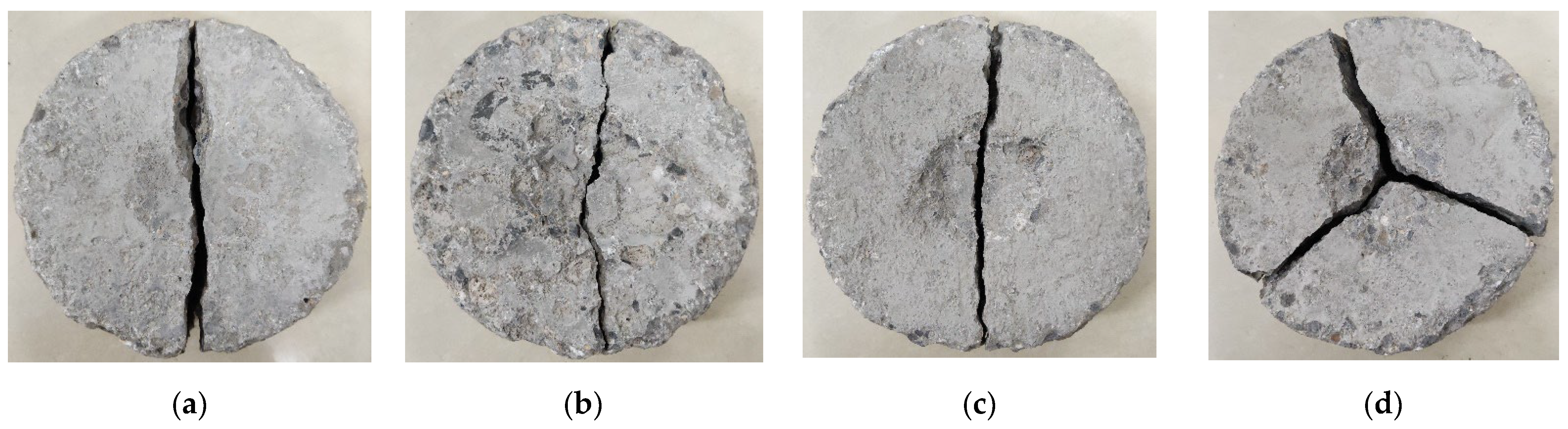
4.1. Impact Specimen Damage Pattern

The impact damage morphology presented by each group of test blocks under the impact load is shown in Figure 5. Under continuous impact hammering, the first crack appeared on the surface and then penetrated the whole plain concrete specimen. The damage patterns of CCG, PC, FAC, and CC specimens were similar with “cracking as destruction” showing obvious brittle damage. In essence, the concrete was unable to prevent the expansion of the internal fine cracks, leading to rapid extension to the surface of the brittle damage. As shown in Figure 5, a small portion of these cracks occurred in the combined zone of cement mortar and coarse aggregate stones, and the majority crossed the cement mortar and light aggregate with a more complex damage trend, while the natural coarse aggregate was rarely damaged. This indicated that the damage was clearly influenced by the type of aggregate. This phenomenon can be explained by the variability in the mechanical properties of different aggregates. Several of the test blocks showed three trigonal and star-shaped cracks under impact loading, which divided the test blocks into three parts.

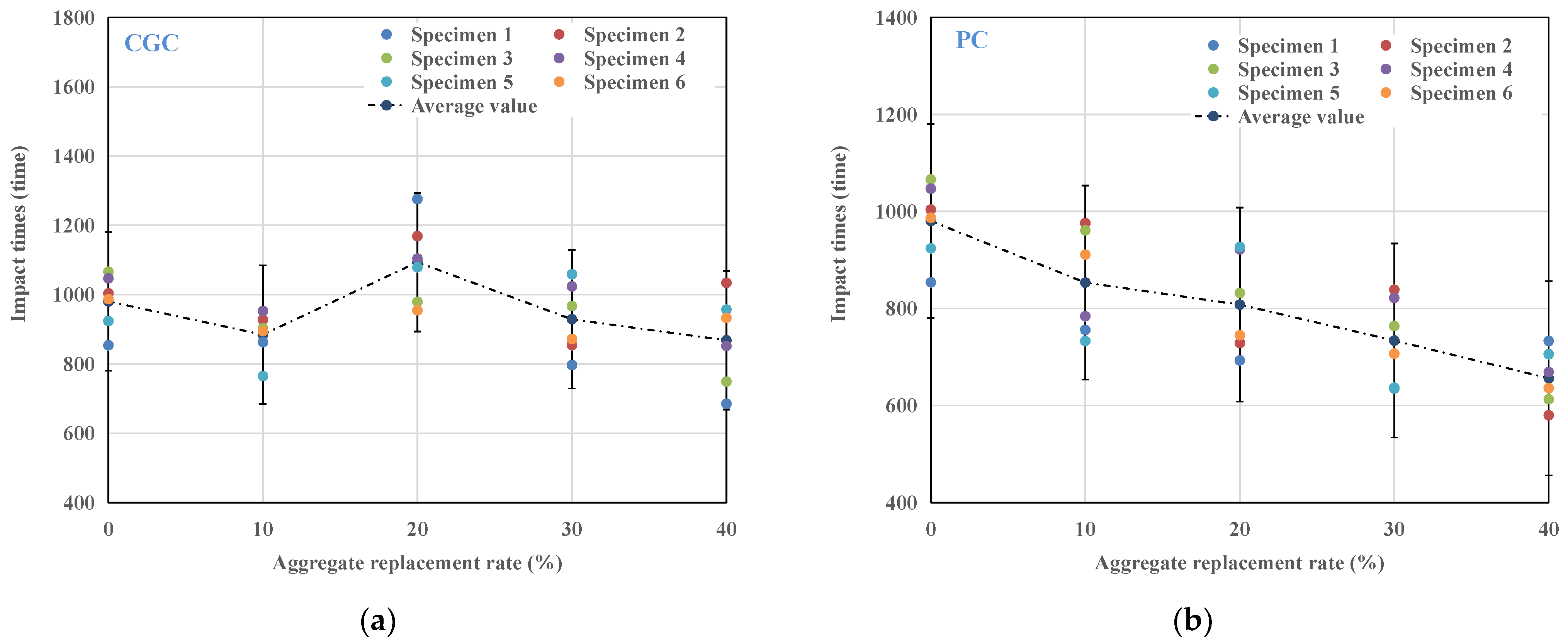
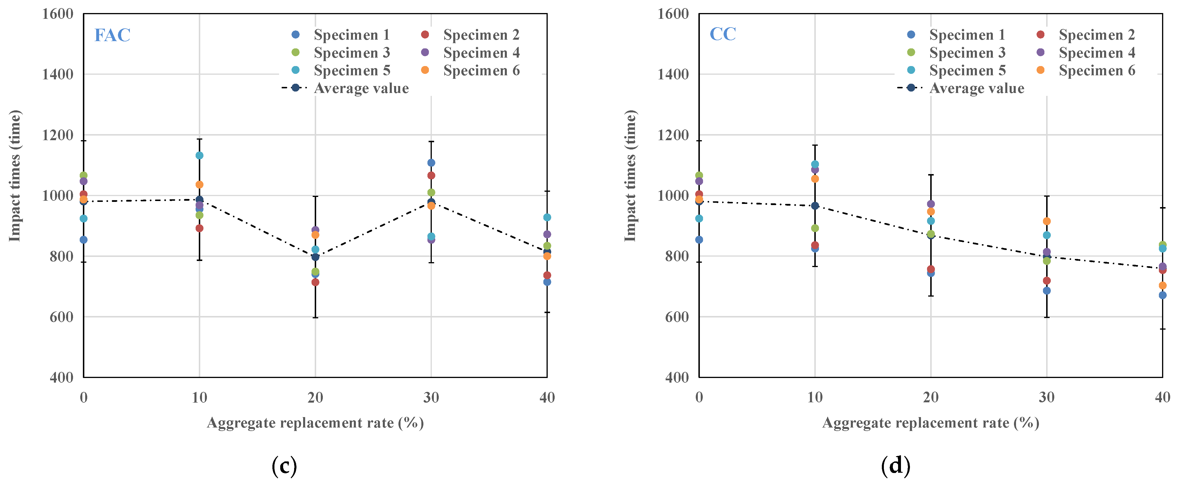
4.2. Impact Performance

The impact test records the number of initial cracks N1 and the number of final cracks N2 for each group of 6 test blocks. The average value was used to calculate the impact energy consumption, which is calculated by the formula
W = N 2 m g h
where W is the impact energy consumption J ; N 2 is the number of impacts when the specimen is damaged; m is the quality of the impact drop hammer, kg (4.5 kg); g is gravitational acceleration (9.81 m/s2); and h is the height of impact hammer drop (0.5 m).
From Table 3, it can be seen that the number of impact resistance varies widely for each group of the six test blocks, indicating a relatively large dispersion of the initial cracking number N1 and final cracking number N2 because of the highly discrete type of concrete. In Figure 6, the variation pattern of the impact number of each group of multi-phase light aggregate concrete can be seen more intuitively. The data analysis and processing of the impact resistance index of each group of specimens leads to Table 3.
From Table 4, using coal gangue ceramsite, pumice aggregate, fly ash ceramsite and coral aggregate to replace part of the coarse aggregate did not obviously improve ductility, and the specimen showed obvious brittle failure. After adding the pumice and coral aggregate, the number of initial and final cracks of PC and CC decreased, and the average impact energy consumption was lower than that for the reference concrete. When the dosage was 40%, the impact energy consumption of PC and CC decreased by 32.89% and 22.34%, respectively. These damaged cracks generally occurred in the cement mortar and lightweight aggregate areas, where the coarse aggregate crushed stone was rarely damaged, indicating that the destruction of concrete was due to the lower strength of pumice and coral aggregates compared to that of coarse aggregate crushed stone.
When adding 20% gangue ceramsite, the impact energy consumption of the specimen increased compared to the reference concrete, and the impact number increased by 8.2%. This was because a certain content of coal gangue ceramsite promoted hydration so that the cement mortar and aggregate matrix were closely combined, and hydration reaction products filled the gap between aggregates, thereby improving concrete performance. When the coal gangue ceramsite exceeded 20%, the impact energy consumption decreased gradually. When it was 40%, the impact energy consumption decreased by 10.66%, demonstrating that excessive coal gangue ceramsite reduced the impact energy consumption of concrete. When the contents of fly ash ceramsite were 10% and 30%, the impact energy consumption increased slightly, which was similar to that of coal gangue ceramsite. Therefore, an appropriate dosage of coal gangue and fly ash ceramsite improved the impact resistance of concrete and reduced cracking sensitivity.

4.3. Impact Resistance Analysis of MLAC Based on Two-Parameter Weibull Distribution Model

4.3.1. Parameter Determination of Two-Parameter Weibull Distribution Model

There are inevitably some tiny cracks during the setting and hardening of cement-based materials. Under the impact load, these tiny cracks continue to expand until the concrete is finally destroyed. Therefore, concrete is essentially in a process of random cumulative fatigue damage. Researchers tried to use various statistical tools to summarize the changes in experimental results. Normal distribution was one of them, but the fitting of shock test results using normal distribution was poor [30,31]. Some scholars found that the impact life of concrete follows the two-parameter Weibull distribution [32,33,34]. As a life prediction model, it is widely used in the failure assessment of brittle materials. Therefore, with the final cracking number, N 2 of each group of multi-phase lightweight aggregate concrete as the initial data, this model was selected to conduct an in-depth study on the impact life of each group of multi-phase lightweight aggregate concrete under different failure probabilities.
The model is a two-parameter function composed of shape parameter β , which determines the shape of the function, and proportional parameter η , which determines the scaling of the function. According to the two-parameter Weibull distribution model, assuming that F ( N ) is the probability density function of the impact life N of the multiphase lightweight aggregate concrete, F ( N ) can be expressed by Equation (2).
F N = β η N η β 1 exp N η β N 0
By integrating Equation (2), the corresponding cumulative distribution function f ( N ) can be obtained, as shown in Equation (3):
f N = 1 exp N η β
The function value corresponding to the cumulative distribution function f ( N ) is also called cumulative failure probability P 1 . The survival probability function value P 2 can then be expressed as
P 2 = exp N η β
Taking the natural logarithm twice for both sides of Equation (4), Equation (5) is obtained:
ln ln 1 P 2 = β ln 1 η + β ln N
Let Y = ln ln 1 / P 2 , X = ln N , then the above equation can be rewritten as
Y = b + a X
The proportional parameter η in Equation (5) can be expressed by Equation (7):
η = exp ( a / b )
Equation (5) can be used to verify whether the impact life of MLAC is subject to the two-parameter Weibull distribution. Through linear regression analysis, the values of parameters a , b and the correlation coefficient R 2 can be obtained. If there is a good linear relationship between Y and X in the linear fitting results, the two-parameter Weibull distribution model can reasonably predict and analyze the impact life of MLAC under different failure probabilities. If there is no linear relationship between Y and X , the model is not suitable for an impact life analysis.
To test whether the impact life of MLAC conforms to the two-parameter Weibull distribution and whether there is a good linear relationship between Y and X , the survival probability needs to be calculated first. The calculation method is shown in Formula (8):
P 2 = 1 i m + 1
where i is the order of each group of experimental data, and m is the total number of samples per group. Through Formulas (5), (6) and (8), with X as the abscissa and Y as the ordinate, linear regression analysis was carried out on the experimental data. The values of regression parameters A, B and correlation coefficient R2 are shown in Table 5.

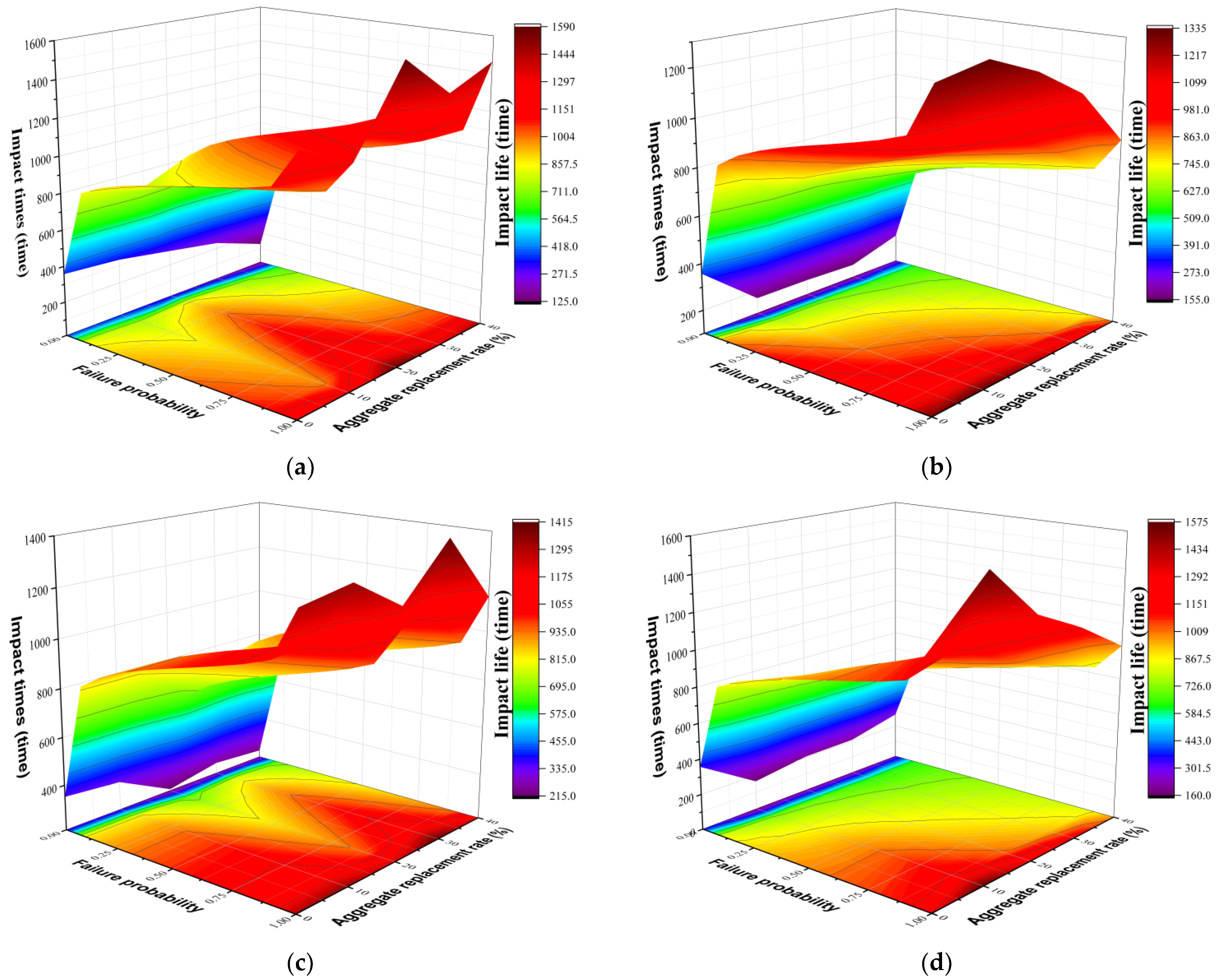
4.3.2. Impact Life Analysis of MLAC under Multiple Factors

Rahmani et al. [32] pointed out that R 2 0.7 could establish a reasonable reliability model at that time. It can be seen from Table 5 that the minimum regression coefficient R2 is 0.798, the maximum is 0.978, and both are greater than 0.7. The linear regression fit is good, and the test results are consistent with the distribution law of the Weibull probability density function, which means that Equation (8) holds. According to Formulas (5)–(8), Formula (9) can be obtained and used to obtain the impact life of an MLAC under different failure probabilities.
N = exp ln ln 1 / ( 1 P 1 ) a b
Parameters a and b can be obtained from Table 4. The impact life of each group of MLAC specimens under different failure probabilities can be obtained through Equation (9), as shown in Table 6.
In the optimization of experimental design, it is difficult to directly determine the optimal value of the factors due to the interaction of multiple factors, so the response surface method came into being. It uses graphic technology to directly reflect the functional relationship between multiple variables such as aggregate replacement rate and failure probability and core elements (impact times) in the system. In the previous section, the ultimate impact times of each MLAC group under different failure probabilities were obtained through the Weibull distribution model. To study the influence of different types and percentages of lightweight aggregate and the failure probability on the impact times of MLACs, three-dimensional response diagrams of four different lightweight aggregate materials under different percentages and different failure probabilities were established.
The data obtained in the previous section were imported into the Origin software to draw the corresponding three-dimensional response diagram, as shown in Figure 7. The x axis is the failure probability, and the y axis is the replacement ratio of the aggregate. It can be seen from Figure 7 that with an increased failure probability and aggregate replacement rate of concrete specimens, the color in the figure gradually changes from purple to dark red. In Figure 7, the contour density of the y axis is greater than that of the x axis, indicating that the influence of the aggregate replacement rate on the impact performance of MLAC was higher than the probability of failure or the failure of the concrete specimens. When the failure probability of MLAC was higher, the corresponding number of the impact resistance was higher. It can be seen in Figure 7a that when the content of coal gangue ceramsite in GCC was between 15% and 25%, the impact resistance of GCG had the best value. In Figure 7b, when the content of pumice aggregate in PC was between 0% and 20%, the impact resistance of PC had the best value. In Figure 7c, when the content of fly ash ceramsite was 0–15% and 25–35%, the impact resistance of FAC had the best value. Figure 7d shows that when the content of coral aggregate in CC was between 5% and 15%, the impact resistance of CC had the best value.

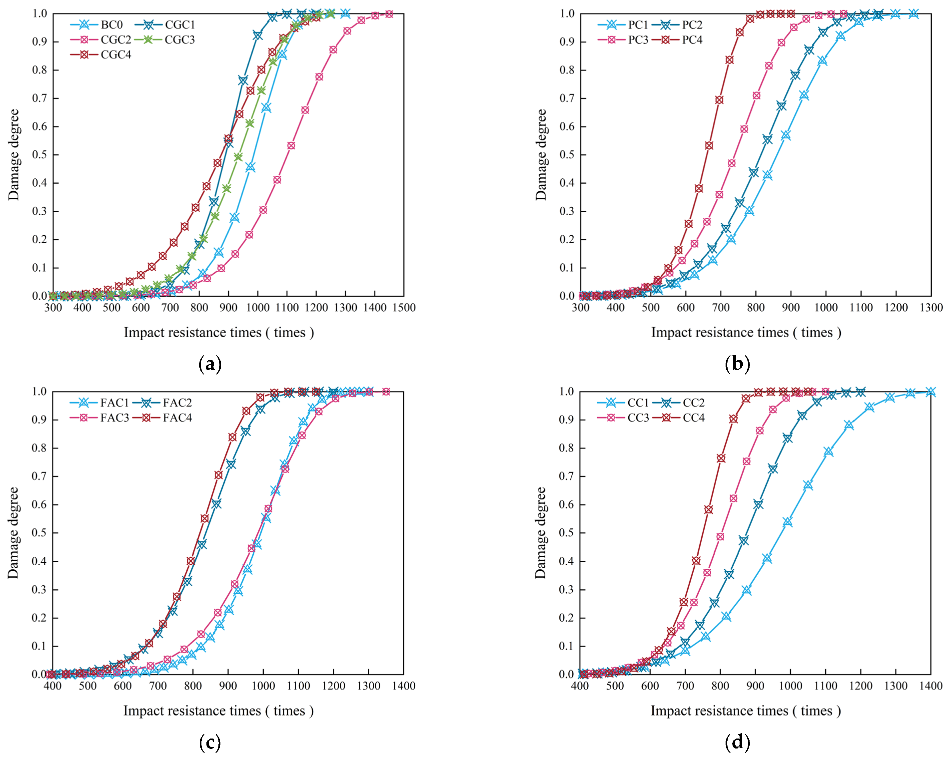
4.3.3. Impact Damage Analysis of MLAC

In the previous section, the two-parameter Weibull distribution model was used to analyze the impact life of each MLAC group under different failure probabilities, but the damage process of MLAC after repeated dynamic loading was not systematically studied. Damage caused by repeated drop hammer impacts on MLAC structures was essentially the result of accumulated damage within the concrete structure after multiple drop hammer impacts.
With the gradual increase in the number of falling hammer impacts, the probability of failure damage also increased, so the probability of failure damage and damage variables of the concrete structure were considered a simultaneous superposition process during the whole impact breakage process. It can be considered that the concrete damage degree and failure probability accumulated simultaneously during the drop hammer impact. When the concrete fails after N times, the failure probability of concrete is P 1 ( N ) = 1 , and the damage degree is D ( N ) = 1 . It can be seen that the failure probability and damage degree of concrete can be treated equivalently, that is, P 1 ( N ) = D ( N ) . In summary, the impact damage model of MLAC based on the two-parameter Weibull distribution can be expressed by Equation (10):
D n = 1 exp n η β
The data in Table 5 are substituted into Equation (7) to obtain β and η . The calculated values are substituted into Equation (10) to obtain the evolution equation of impact damage resistance for each group of multiphase light aggregate concrete under repeated falling hammer impact loads. To improve accuracy, six specimens were used in each group. The fitting formula was obtained by taking the average value of the experimental data, as shown in Table 7.
According to the impact damage evolution equation in Table 7, the damage degree curve of each group of lightweight aggregate concrete specimens can be drawn, as shown in Figure 8. From the damage degree change curve, it can be seen that during the drop hammer impact tests, the damage degree change of the concrete was not obvious at the initial stage because the internal structure of concrete tended to be stable, and the degree of crack extension was low. The concrete with 20% coal gangue ceramsite had the maximum limit impact resistance times, which showed that the CGC with this content had the best impact resistance. With the increase in impact times, the damage degree of concrete increased sharply. When the damage degree was 1, the concrete appeared through the cracks and was completely destroyed. The Weibull distribution probability damage model and the experimental data had high similarity, which showed that the model described the damage variation of concrete specimens during impact resistance well.

5. Conclusions

The following conclusions can be drawn from the mechanical and impact test results of MLAC:
  • With the increase in coal gangue ceramsite, the mechanical properties of CGC first increased and then decreased. With the increase in fly ash ceramsite, the mechanical properties of FAC increased, decreased, increased again and finally decreased. With the increase in coral aggregate content, the CC increased then decreased. With the increase in pumice aggregate, the PC decreased. The comprehensive performance was CGC > FAC > CC > PC.
  • When coal gangue ceramsite was 20%, the mechanical properties and impact resistance of concrete were the best. The compressive, flexural and splitting tensile strength and the impact energy consumption increased by 29.25%, 19.93%, 13.89% and 8.2%, respectively, compared with the reference concrete.
  • The impact test results of MLAC obeyed the distribution law of the two-parameter Weibull distribution model, which can be used to predict and describe the impact life of multi-phase lightweight aggregate concrete under different failure probabilities.
  • The impact resistance of MLAC under multiple factors was analyzed in depth. The analysis showed that the influence of the aggregate replacement rate on the impact resistance of multi-phase lightweight aggregate concrete was higher than the probability of failure or the failure of the concrete specimens.
  • Through the establishment of the impact damage evolution equation, the damage degradation of each specimen under drop hammer impact was studied in depth. The variation law of the data derived from the equation was highly consistent with the experimental results. The damage degradation of MLAC under dynamic load can be reasonably described by the equation.

6. Prospect

In this experiment, the effects of four lightweight aggregates on the mechanical properties and impact resistance of MLAC were studied, and the durability of MLAC was further studied in the follow-up work. Whether the addition of fibers or other cementitious materials can improve the mechanical properties and durability of concrete can be considered.

Author Contributions

Conceptualization, J.M. and A.Z.; methodology, Z.X. and J.M.; software, J.M.; validation, J.M., A.Z. and Z.X.; formal analysis, Z.X., J.M. and Z.L.; investigation, J.M., Z.L. and S.C.; resources, J.M.; data curation, J.M. and C.W.; writing—original draft preparation, J.M.; writing—review and editing, J.M.; visualization, J.M. and B.Z.; supervision, J.M. and A.Z.; project administration, J.M. and A.Z.; funding acquisition, J.M. and A.Z. All authors have read and agreed to the published version of the manuscript.

Funding

This research was funded by An Zhou, grant number BSQD12155.

Institutional Review Board Statement

Not applicable.

Informed Consent Statement

Not applicable.

Data Availability Statement

The data presented in this study are available on request from the corresponding author.

Conflicts of Interest

The author declares no conflict of interest.

References

  1. Global ABC/IEA/UNEP (Global Alliance for Buildings and Construction, International Energy Agency, and the U.N.E.P.). Global ABC Roadmap for Buildings and Construction: Towards a Zero-Emission, Efficient and Resilient Buildings and Construction Sector; Global ABC/IEA/UNEP: Paris, France, 2020. [Google Scholar]
  2. Jabłońska, B.; Kityk, A.V.; Busch, M.; Huber, P. The structural and surface properties of natural and modified coal gangue. J. Environ. Manag. 2017, 190, 80–90. [Google Scholar] [CrossRef] [PubMed]
  3. Toniolo, N.; Boccaccini, A.R. Fly ash-based geopolymers containing added silicate waste. A review. Ceram. Int. 2017, 43, 14545–14551. [Google Scholar] [CrossRef]
  4. Cristelo, N.; Castro, F.; Miranda, T.; Abdollahnejad, Z.; Fernández-Jiménez, A. Iron and aluminium production wastes as exclusive components of alkali activated binders—Towards a sustainable alternative. Sustainability 2021, 13, 9938. [Google Scholar] [CrossRef]
  5. Bilir, T.; Aygun, B.F.; Shi, J.; Gencel, O.; Ozbakkaloglu, T. Influence of Different Types of Wastes on Mechanical and Durability Properties of Interlocking Concrete Block Paving (ICBP): A Review. Sustainability 2022, 14, 3733. [Google Scholar] [CrossRef]
  6. Nicoara, A.I.; Stoica, A.E.; Vrabec, M.; Šmuc Rogan, N.; Sturm, S.; Ow-Yang, C.; Gulgun, M.A.; Bundur, Z.B.; Ciuca, I.; Vasile, B.S. End-of-life materials used as supplementary cementitious materials in the concrete industry. Materials 2020, 13, 1954. [Google Scholar] [CrossRef] [Green Version]
  7. Ashfaq, M.; Heera Lal, M.; Moghal, A.A.B. Utilization of coal gangue for earthworks: Sustainability perspective. In Advances in Sustainable Construction and Resource Management; Springer: Berlin/Heidelberg, Germany, 2021; pp. 203–218. [Google Scholar]
  8. Gao, S.; Zhang, S.; Guo, L. Application of Coal Gangue as a Coarse Aggregate in Green Concrete Production: A Review. Materials 2021, 14, 6803. [Google Scholar] [CrossRef]
  9. Kockal, N.U.; Ozturan, T. Durability of lightweight concretes with lightweight fly ash aggregates. Constr. Build. Mater. 2011, 25, 1430–1438. [Google Scholar] [CrossRef]
  10. Jayabharath, P.; Kesavan, G. Study on Impact Strength of Fly Ash Aggregate Concrete. IOSR J. Mech. Civ. Eng. 2017, 14, 75–82. [Google Scholar] [CrossRef]
  11. Dahim, M.; Abuaddous, M.; Al-Mattarneh, H.; Rawashdeh, A.; Ismail, R. Enhancement of road pavement material using conventional and nano-crude oil fly ash. App. Nanosci. 2021, 11, 2517–2524. [Google Scholar] [CrossRef]
  12. Hemalatha, T.; Ramaswamy, A. A review on fly ash characteristics–Towards promoting high volume utilization in developing sustainable concrete. J. Clean. Prod. 2017, 147, 546–559. [Google Scholar] [CrossRef]
  13. Yıldırım, H.; Özturan, T. Impact resistance of concrete produced with plain and reinforced cold-bonded fly ash aggregates. J. Build. Eng. 2021, 42, 102875. [Google Scholar] [CrossRef]
  14. Kurt, M.; Gül, M.S.; Gül, R.; Aydin, A.C.; Kotan, T. The effect of pumice powder on the self-compactability of pumice aggregate lightweight concrete. Constr. Build. Mater. 2016, 103, 36–46. [Google Scholar] [CrossRef]
  15. Kotan, T.; Gül, R. Effect of atmospheric pressure steam curing to mechanical properties of lightweight concrete produced with Erzurum–Pasinler pumice. Mach. Technol. Mater. Int. Virtual J. 2010, 43, 4–5. [Google Scholar]
  16. Öz, H.Ö. Properties of pervious concretes partially incorporating acidic pumice as coarse aggregate. Constr. Build. Mater. 2018, 166, 601–609. [Google Scholar] [CrossRef]
  17. Hossain, K.; Ahmed, S.; Lachemi, M. Lightweight concrete incorporating pumice based blended cement and aggregate: Mechanical and durability characteristics. Constr. Build. Mater. 2011, 25, 1186–1195. [Google Scholar] [CrossRef]
  18. Kurt, M.; Aydin, A.C.; Gül, M.S.; Gül, R.; Kotan, T. The effect of fly ash to self-compactability of pumice aggregate lightweight concrete. Sadhana 2015, 40, 1343–1359. [Google Scholar] [CrossRef]
  19. Amel, C.L.; Kadri, E.-H.; Sebaibi, Y.; Soualhi, H. Dune sand and pumice impact on mechanical and thermal lightweight concrete properties. Constr. Build. Mater. 2017, 133, 209–218. [Google Scholar] [CrossRef]
  20. Bakis, A. The usability of pumice powder as a binding additive in the aspect of selected mechanical parameters for concrete road pavement. Materials 2019, 12, 2743. [Google Scholar] [CrossRef] [Green Version]
  21. Johra, H.; Margheritini, L.; Antonov, Y.I.; Frandsen, K.M.; Simonsen, M.E.; Møldrup, P.; Jensen, R.L. Thermal, moisture and mechanical properties of Seacrete: A sustainable sea-grown building material. Constr. Build. Mater. 2021, 266, 121025. [Google Scholar] [CrossRef]
  22. Arumugam, R.; Ramamurthy, K. Study of compressive strength characteristics of coral aggregate concrete. Mag. Concr. Res. 1996, 48, 141–148. [Google Scholar] [CrossRef]
  23. Kakooei, S.; Akil, H.M.; Jamshidi, M.; Rouhi, J. The effects of polypropylene fibers on the properties of reinforced concrete structures. Constr. Build. Mater. 2012, 27, 73–77. [Google Scholar] [CrossRef]
  24. Niu, D.; Su, L.; Luo, Y.; Huang, D.; Luo, D. Experimental study on mechanical properties and durability of basalt fiber reinforced coral aggregate concrete. Constr. Build. Mater. 2020, 237, 117628. [Google Scholar] [CrossRef]
  25. Rao, L.; Wang, L.; Zheng, Y. Experimental Research on Mechanical Properties and Compression Constitutive Relationship of PVA Fiber-Reinforced Coral Concrete. Materials 2022, 15, 1762. [Google Scholar] [CrossRef]
  26. Cheng, S.; Shui, Z.; Sun, T.; Yu, R.; Zhang, G. Durability and microstructure of coral sand concrete incorporating supplementary cementitious materials. Constr. Build. Mater. 2018, 171, 44–53. [Google Scholar] [CrossRef]
  27. Wang, Y.; Qiu, J.; Deng, W.; Xing, J.; Liang, J. Factors affecting brittleness behavior of coal-gangue ceramsite lightweight aggregate concrete. Front. Mater. 2020, 7, 554718. [Google Scholar] [CrossRef]
  28. Shafigh, P.; Nomeli, M.A.; Alengaram, U.J.; Mahmud, H.B.; Jumaat, M.Z. Engineering properties of lightweight aggregate concrete containing limestone powder and high volume fly ash. J. Clean. Prod. 2016, 135, 148–157. [Google Scholar] [CrossRef]
  29. ACI Committee 544. Measurement of Properties of Fiber Reinforced Concrete. ACI Mater. J. 1998, 85, 83–93. [Google Scholar]
  30. Yoo, D.-Y.; Banthia, N. Impact resistance of fiber-reinforced concrete–A review. Cement Concr. Compos. 2019, 104, 103389. [Google Scholar] [CrossRef]
  31. Ding, Q.; Xiang, W.; Zhang, G.; Hu, C. Effect of Pre-wetting Lightweight Aggregates on the Mechanical Performances and Microstructure of Cement Pastes. J. Wuhan Univ. Technol. Mater. Sci. Ed. 2020, 35, 140–146. [Google Scholar] [CrossRef]
  32. Rahmani, T.; Kiani, B.; Shekarchi, M.; Safari, A. Statistical and experimental analysis on the behavior of fiber reinforced concretes subjected to drop weight test. Constr. Build. Mater. 2012, 37, 360–369. [Google Scholar] [CrossRef]
  33. Mohammadi, Y.; Kaushik, S. Flexural fatigue-life distributions of plain and fibrous concrete at various stress levels. J. Mater. Civil Eng. 2005, 17, 650–658. [Google Scholar] [CrossRef]
  34. Murali, G.; Abid, S.R.; Amran, Y.M.; Abdelgader, H.S.; Fediuk, R.; Susrutha, A.; Poonguzhali, K. Impact performance of novel multi-layered prepacked aggregate fibrous composites under compression and bending. Structures 2020, 28, 1502–1515. [Google Scholar] [CrossRef]
Figure 1. (a) Coal gangue ceramsite; (b) pumice aggregate; (c) fly ash ceramsite; (d) coral aggregate.
Sustainability 14 09606 g001
Figure 2. Relationship between compressive strength and lightweight aggregate content.
Sustainability 14 09606 g002
Figure 3. Relationship between flexural strength and lightweight aggregate content.
Sustainability 14 09606 g003
Figure 4. Relationship between splitting tensile strength and lightweight aggregate contents.
Sustainability 14 09606 g004
Figure 5. Test block damage pattern (a) CGC; (b) PC; (c) FAC; (d) CC.
Sustainability 14 09606 g005
Figure 6. Relationship between impact resistance times of MLAC and aggregate content (a) CGC; (b) PC; (c) FAC; (d) CC.
Sustainability 14 09606 g006aSustainability 14 09606 g006b
Figure 7. Multi-factor three-dimensional response diagram: (a) GCG, (b) PC, (c) FAC, (d) CC.
Sustainability 14 09606 g007
Figure 8. Concrete Weibull impact damage prediction curve: (a) GCG, (b) PC, (c) FAC, (d) CC.
Sustainability 14 09606 g008
Table 1. Physical properties of light aggregate.
No.Bulk Density
(kg/m3)
Apparent Density
(kg/m3)
Water Absorption (%)Tube Compressive Strength (MPa)
1 h24 h
Coal gangue ceramsite97517305.077.436.8
Pumice aggregate690159316.4417.322.98
Fly ash ceramsite 650132312.5112.986.5
Coral aggregate91518418.511.03.1
Table 2. Mix design of MLAC.
No.Substitution Rate (kg/m3)Water (kg/m3)Cement (kg/m3)Fly Ash (kg/m3)Gravel (kg/m3)Lightweight Aggregate (kg/m3)Sand (kg/m3)Water
Reducing Agent (kg/m3)
BC00180366.491.6107006562
CGC110180366.491.69631076562
CGC220180366.491.68562146562
CGC330180366.491.67493216562
CGC440180366.491.66424286562
PC110180366.491.69631076562
PC220180366.491.68562146562
PC330180366.491.67493216562
PC440180366.491.66424286562
FAC110180366.491.69631076562
FAC220180366.491.68562146562
FAC330180366.491.67493216562
FAC440180366.491.66424286562
CC110180366.491.69631076562
CC220180366.491.68562146562
CC330180366.491.67493216562
CC440180366.491.66424286562
Table 3. For the number of initial cracks N1 and the number of final cracks N2.
No.N1/N2
123456
BC0853/8541003/10041065/10661046/1047923/924986/987
CGC1861/863927/928902/903952/953763/765894/895
CGC21274/12761167/1169976/9791102/11041077/1079953/955
CGC3796/797853/854965/9671023/10241058/1059871/872
CGC4684/6851034/1034749/749852/852957/957932/933
PC1755/756975/976959/961783/784732/733910/911
PC2692/693728/729831/832921/922925/927744/745
PC3635/635838/839764/764822/822637/637706/707
PC4732/733580/580613/613669/669706/706636/636
FAC1954/955891/892933/935967/9681131/11321035/1036
FAC2740/741713/714948/949885/886821/822869/870
FAC31107/11081065/10661009/1010853/854864/865965/966
FAC4715/715736/737834/834872/872928/928800/800
CC1823/825835/836891/8921084/10851102/11031054/1055
CC2742/744756/757872/873971/972915/916946/947
CC3685/686718/719783/784813/814868/869914/915
CC4670/671754/754836/837765/766825/825703/703
Table 4. Impact resistance index analysis results.
No.Average of the Number of ImpactsImpact Energy Consumption/(w/J)
N1N2N2 − N1
BC0976977121,564.833
CGC1913914120,174.265
CGC210551057223,330.633
CGC3928929120,505.353
CGC4873873019,269.293
PC1852853118,827.843
PC2807808117,834.58
PC3734734016,201.215
PC4656656014,479.56
FAC1985986121,763.485
FAC2829930120,527.425
FAC3977978121,586.905
FAC4814814017,967.015
CC1965966121,322.035
CC2867868119,158.93
CC3797798117,613.855
CC4759759016,753.028
Table 5. Regression parameters a, b and correlation coefficient R2.
No.Regression ParametersCorrelation Coefficient
a b R2
BC010.949−75.8540.973
CGC111.356−77.4940.899
CGC28.208−57.8660.927
CGC38.018−55.2240.943
CGC45.803−39.6740.976
PC16.807−46.3640.863
PC27.011−47.3570.880
PC37.21−47.9970.898
PC410.342−67.5190.978
FAC110.151−70.4220.839
FAC28.243−55.8330.956
FAC38.322−57.7310.93
FAC49.088−61.3450.956
CC16.249−43.3730.798
CC27.699−52.5190.902
CC38.279−55.7460.973
CC411.148−74.1810.809
Table 6. Impact life of each group of specimens under different failure probabilities (times).
No. P 1 = 0.1 P 1 = 0.3 P 1 = 0.5 P 1 = 0.7 P 1 = 0.9
BC083192998710381101
CGC1754840890935990
CGC28761017110211791276
CGC374086293610031087
CGC46327808749621075
PC16527808609331026
PC2622741814881966
PC3570675740799874
PC4551620661697742
FAC182593199410491118
FAC2665771836894967
FAC378691098510531138
FAC4667763820872936
CC172187697510651181
CC26858028759401022
CC3640742804859929
CC4634707751789836
Table 7. Weibull distribution probability damage model coefficients.
B C : D N = 1 exp n 1020 . 356 10 . 949 C G C 1 : D N = 1 exp n 919 . 547 11 . 356 C G C 2 : D N = 1 exp n 1152 . 275 8 . 209
C G C 3 : D N = 1 exp n 979 . 671 8 . 018 C G C 4 : D N = 1 exp n 932 . 017 5 . 803 P C 1 : D N = 1 exp n 908 . 235 6 . 807
P C 2 : D N = 1 exp n 858 . 317 7 . 011 P C 3 : D N = 1 exp n 778 . 508 7 . 21 P C 4 : D N = 1 exp n 684 . 397 10 . 342
F A C 1 : D N = 1 exp n 1029 . 858 10 . 151 F A C 2 : D N = 1 exp n 874 . 61 8 . 243 F A C 3 : D N = 1 exp n 1029 . 962 8 . 322
F A C 4 : D N = 1 exp n 853 . 94 9 . 088 C C 1 : D N = 1 exp n 1033 . 501 6 . 249 C C 2 : D N = 1 exp n 917 . 754 7 . 699
C C 3 : D N = 1 exp n 840 . 127 8 . 279 C C 4 : D N = 1 exp n 776 . 011 11 . 148
Publisher’s Note: MDPI stays neutral with regard to jurisdictional claims in published maps and institutional affiliations.

