Abstract
Modern road vehicles are more and more often being equipped with electric actuators. These are intended to play critical roles in passengers comfort and safety. Among the electrified components onboard road vehicles, one can distinguish electric power steering (EPS) systems, which have been the subject of intensive investigations covering both design and control aspects. The abilities of several AC motor topologies to fulfil the EPS systems’ requirements have been assessed by a large scientific community in both academia and industry. The present work was aimed at the prediction of the electromagnetic features of the flux-switching permanent magnet machines (FSPMMs), with an emphasis on the air gap flux density. The latter was firstly formulated while neglecting the slotting effect at both sides of the air gap. Then, stator and rotor permeance functions, taking into account the slotting effect and the PM flux concentrating arrangement, were incorporated into the derived flux density spatial repartition. Moreover, the accuracy of the latter was improved through two dedicated correction functions that take into account the rotor position and the magnetic saturation. The last part of the paper presents a simple approach to enhance the developed torque of FSPMMs in an attempt to meet the EPS requirements.
1. Introduction
Until four decades ago, electrical AC machines were designed accounting for the fact that they were intended to be grid-connected. This led to the well-known conventional machines (induction and DC-excited synchronous machines) in which the stator windings are sinusoidally distributed in slots around the air gap so as to couple optimally with the grid sinusoidal supply. Starting from the 1980s, the emergence of power electronic converters removed the need for that concept as the basis for machine design. A new approach assumes that the best machine design is the one that simply produces the optimum match between the electrical machine and the power electronic converter. This has led to the so-called converter-fed machines. Much attention is presently focused upon the design of new converter-fed machines in which many conventional rules are rethought, such as (i) making multi-phase rather than three-phase machines, (ii) changing the winding shape and arrangement, (iii) changing the magnetic circuit material and geometry, (iv) changing radial, axial or circumferential flux paths, (v) opting for dual excitation in the stator rather than in both sides of the air gap and so on.
Due to this trend, many converter-fed machine topologies have been introduced and are currently under investigation. Among these, one can distinguish the flux-switching permanent magnet machines (FSPMMs). They were introduced in [1], where a procedure dedicated to the design of flux-switch alternators is presented. It covers candidates characterized by a rated power ranging from 100 to 5000 W and a rated speed ranging from 10,000 to 50,000 rpm.
Since the works of Rauch and Johnson [1], much interest has been addressed to FSPMMs due to their robust and passive rotors. In [2], Hua et al. treated the optimization of the rotor pole-arc of a FSPMM equipped with 12 stator teeth and 10 rotor poles, in an attempt to minimize the harmonic content of its back-EMF. In [3], Gysen et al. proposed a model of flux-switching permanent magnet machines based on the Fourier expansion of the air gap flux density. The proposed model enabled the prediction of the electromagnetic torque, whose finite element analysis (FEA) validation revealed some discrepancies. In [4], Wang et al. initiated their work with an investigation of the origin of the cogging torque exhibited by FSPMMs. Then, they proposed a design approach, based on teeth notching, to reduce the cogging torque. In [5], Yan et al. investigated the cogging torques of single and three-phase transverse-flux FSPMMs. They found that the ratios of stator and rotor core circumferential widths to pole pitch are the key parameters to the minimization of the cogging torque. In [6], Wu and Zhu investigated the effects of the modulation of rotor saliency and magnetic gearing on the torque production of FSPMMs, considering different armature winding arrangements and stator lamination segment geometries. In [7], Zeng et al. developed a permeance-magnetomotive force model of FSPMMs that enables the derivation of the the air-gap flux density produced by both stator excitations (PMs and AC current fed armature). An analysis of the harmonic content of both air-gap flux density components has revealed several effective harmonic pairs which share the same rank and rotational speed. In [8], Zhao et al. treated the analysis and reduction of PM eddy current loss in a four-phase FSPMM. The contribution to the PM eddy current loss of each effective harmonic of the air gap flux density was identified. Then, the effectiveness of two concepts of flux barriers in the rotor magnetic circuit to reduce the PM eddy current loss was proven. However, this led to a reduction in the torque and may compromise the rotor’s mechanical robustness. In [9], Hu et al. derived the so-called improved sub-domain model of FSPMMs. It is based on the identification of the major harmonics of the flux density in each sub-domain thanks to the incorporation of a permeance function of the air gap. In [10], Zhu and Xu presented the design and performance assessment of a bearingless FSPMM. The proposed concept is equipped with a torque winding and a suspension force in the armature. Special attention has been paid to the reduction of the cogging torque considering the PM chamfering technique. In [11], Wu et al. investigated a dual stator single rotor DC-excited FSPMM. It is equipped with an armature in the outer stator and a field in the inner one. The rotor is made up of iron pieces linked by iron bridges. Special attention has been paid to the investigation of the effect of the rotor iron bridges on the back-EMF induced in the field. In [12], Chen et al. introduced a FSPMM equipped with an auxiliary set of PMs inserted in pairs of notches located in the stator teeth. The additional PMs enabled an improvement in the torque production with an increase in the average value and a reduction in the ripple. However, it should be underlined that that was achieved at the expense of an increase in the cost and the complexity of the manufacturing process.
From the above literature review, it is clear that, in spite of the dense harmonic content of their flux density spatial repartitions, FSPMMs could exhibit a low ripple torque capability, especially in notched teeth designs. Moreover, the high mechanical robustness of their rotors, the high fault-tolerance of their armature windings, and the simplicity of their control make them viable candidates for electric power steering (EPS) applications. Basically, as the key actuator in an EPS system, the electric motor converts its input electric power into the mechanical power demanded for the steering maneuvers. The requirements for the electric motor in an EPS system are similar to those in servo motor applications, which has to fulfill a high torque/power density, achieved with low inertia, low torque ripple, improved compactness, high fault-tolerance, and safety. Regarding the latter, safety requirements demand that the steering functionality moves from fail-safe to fail-operational for highly automated systems such as the steer-by-wire concepts.
EPS motorization has been the subject of intensive investigations during the past decades. In [13], Bianchi et al. proposed a fault-tolerant interior permanent magnet (IPM) motor dedicated to electric power steering. It consists in a redundant concept that combines two motors on the same shaft. In [14], Saha et al. treated the optimization of a spoke type brushless AC motor in order to reduce the cogging torque and then to meet the requirements of EPS systems. In [15], Liu et al. proposed a tubular linear electromagnetic set composed by a MP motor and a magnetic gear dedicated to the EPS system applications. In [16], Park et al. compared three shapes of the surface-mounted PMs of a motor dedicated to EPS applications. It has been found that the reduction in the torque ripple is allied to a loss in the average torque. In [17], Yang et al. proposed and compared dual three-phase SPM and IPM fractional-slot machines which are fail-operational for safety critical applications, such as steer-by-wire SPM applications.
To the authors’ knowledge, no previous work regarding the feasibility to equip EPS systems with FSPMMs has been reported in the literature. The present work proposes a simple approach to improve the torque production capabilities of FSPMMs in an attempt to meet the EPS requirements. It consists of injecting harmonic currents generating torque components that cancel the ones acting as brakes among those resulting from the fundamental current. Prior to doing so, special attention is paid to the analytical prediction of the air gap flux density. Such a prediction is initiated assuming smooth stator and rotor. Then, the slotting effect and the PM concentrating flux arrangement are taken into account by the incorporation of stator and rotor permeance functions. Moreover, the accuracy of the predicted flux density spatial repartition is improved using two dedicated correction functions that take into account the rotor position and the magnetic saturation.
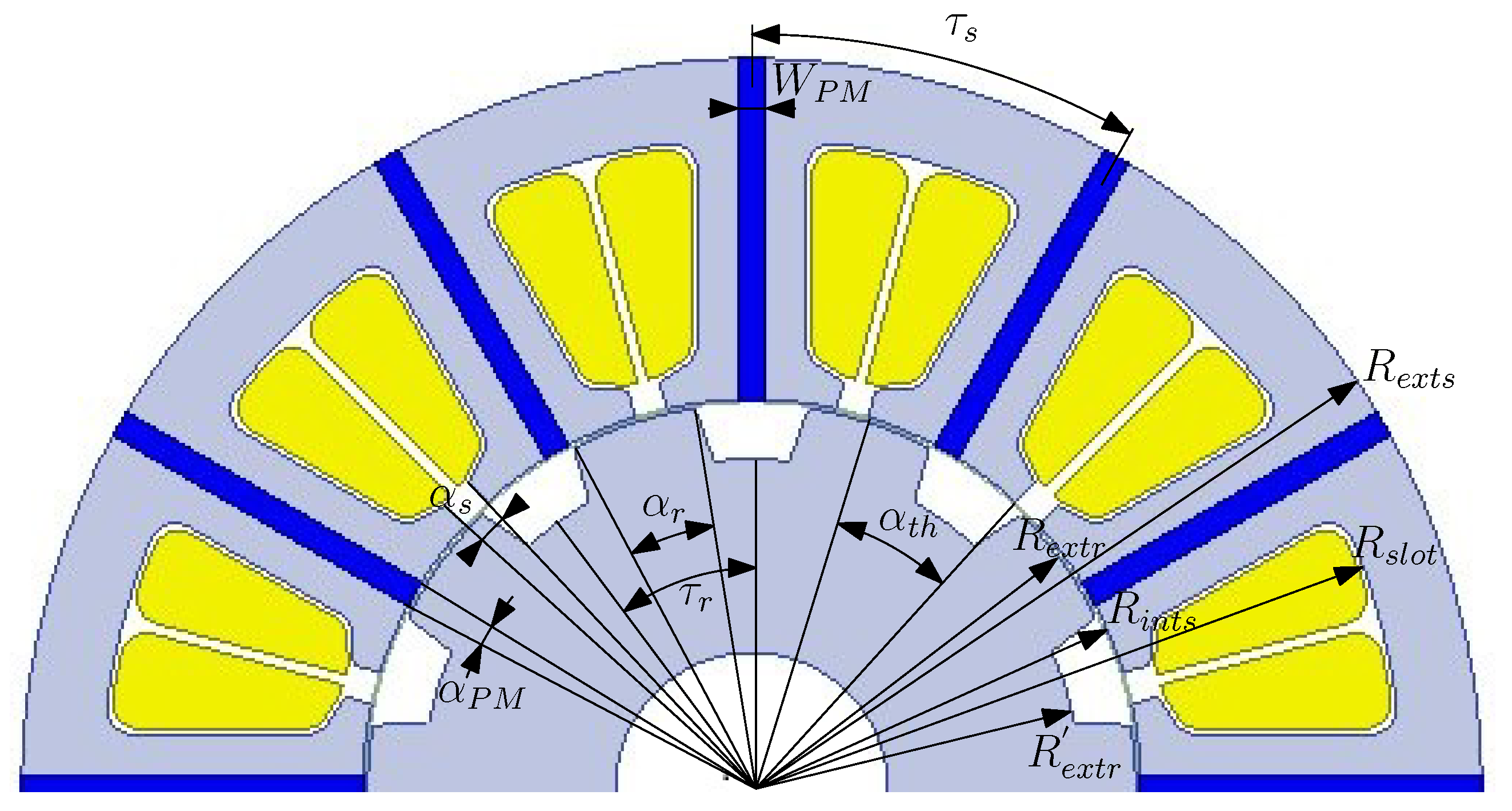
2. Analytical Formulation of FSPMM Features
2.1. PM Air Gap Flux Density
For the sake of simplicity, let us assume that the rotor of the FSPMM has a smooth surface (slotless rotor). The radial component of the air gap flux density created by the stator PMs in the middle of the air gap, , could be deduced from the air gap magnetomotive force distribution . The latter is expressed in the form of a Fourier series expansion as follows:
where is the mechanical angle described along the airgap and is number of PM pairs which is the half of the number of the stator slots , and is expressed as follows:
where is air gap magnetization vector due to the PMs, with:
where:
- , , and are the magnet remanence, relative permeability, and width, respectively;
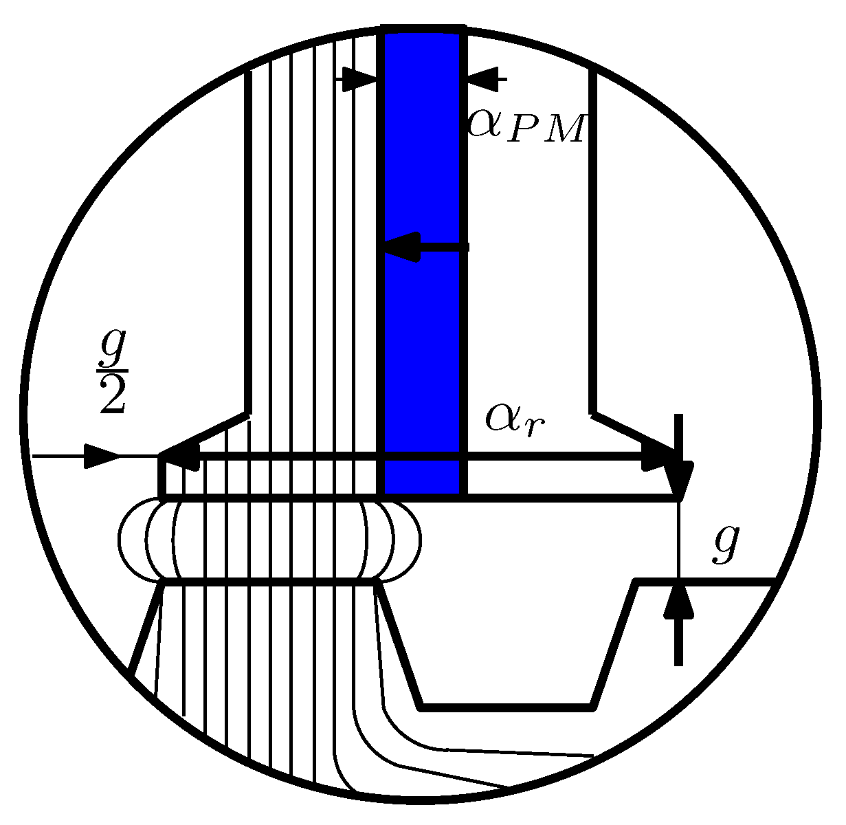
- is the angular PM width at the air-gap stator inner border;
- g is the air gap thickness, with .
The above-described and other geometrical parameters involved in the air gap flux density formulation are identified in Figure 1.
Figure 1.
Half of the cross-section of the FSPMM under study.
2.2. Permeance Functions
For the sake of an accurate prediction of the air gap flux density, permeance functions are considered to account for the stator and rotor saliency. Then, the expression of is deduced from as follows:
where is a permeance function that varies according to the considered saliency (or saliencies).
2.2.1. Stator Permeance Functions
Permeance Function Accounting for the Slotting Effect
Accounting for the slotting effect, is a static permenance function that depends only of the spatial position :
where and are expressed as follows:
where is the stator slot opening to the slot pitch ratio.
Permeance Function Accounting for the PM Flux Concentrating Arrangement
In the manner of , the second stator permeance function takes into account the PM flux concentrating arrangement, denoted , is static and depends only of the position :
where and are expressed as follows:
where is the PM opening to the slot pitch ratio .
2.2.2. Rotor Permeance Function
The rotor permeance function varies with the position in the air gap and the rotor one :
where is the number of the rotor poles which is equal to the number of the rotor teeth , and and are expressed as follows:
where is the rotor slot opening to the rotor slot pitch ratio.
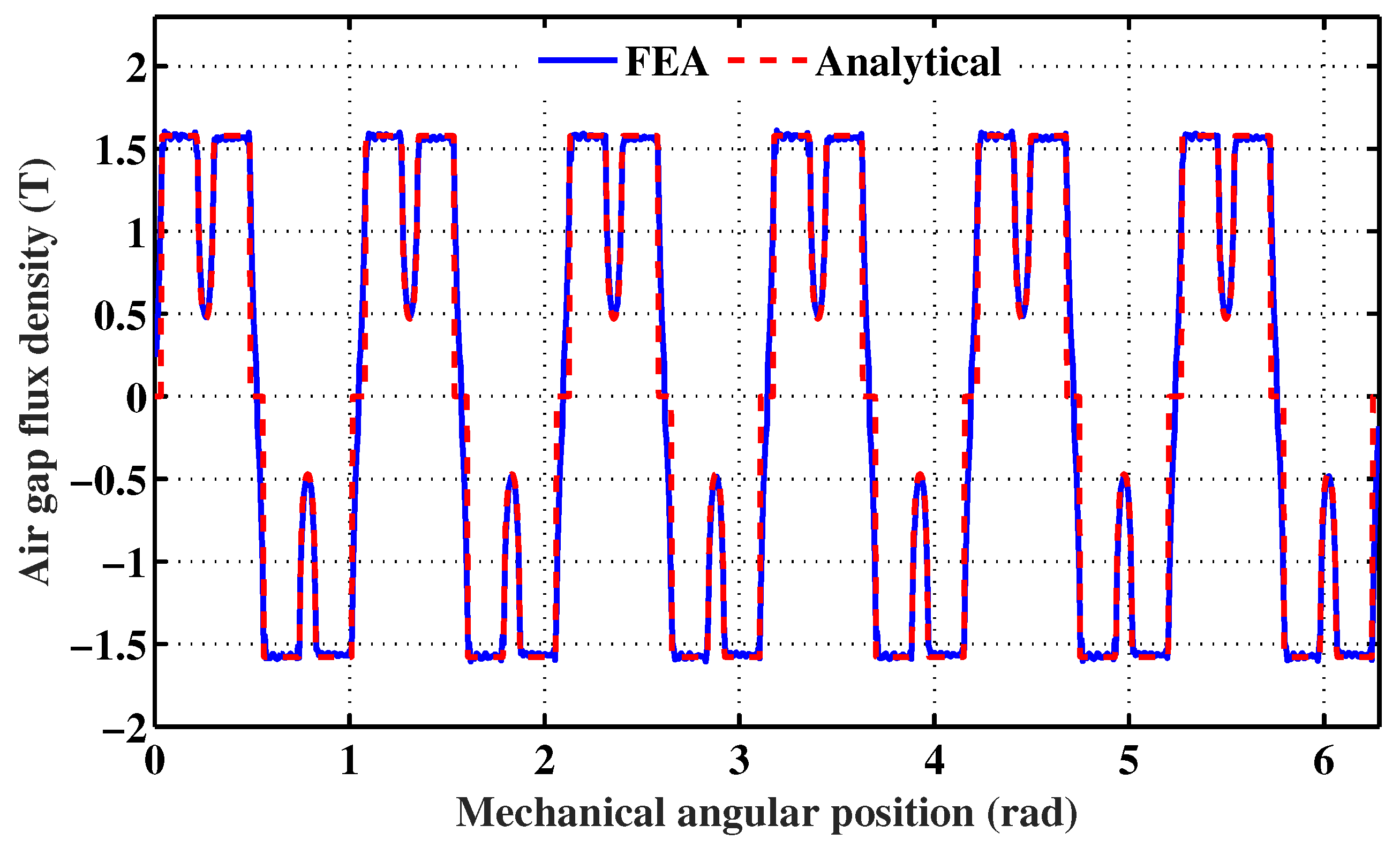
2.3. Improvement of the Accuracy of the PM Air Gap Flux Density Prediction
Beyond the permeance functions, the sharp double saliency of FSPMMs makes necessary the incorporation of two correction factors in the formulation of the air gap flux density, in order to account for: (i) the rotor position and (ii) the magnetic saturation.
2.3.1. Correction Allied to the Rotor Position Variation
Under the assumption of a slotless rotor, the flux generated by a stator PM flows according to the path illustrated in Figure 2a. In this case, the rotor position dependent correction function, denoted , is equal to unity.
Figure 2.
Flux tube surface in the air gap (hatched in blue). Legend: (a) Case of a slotless rotor, (b) position of minimum flux linkage (PM in the stator facing the middle of a slot in the rotor), (c) position of maximum flux linkage (PM in the stator facing the middle of a rotor tooth).
Accounting for the rotor slotting effect, the correction function is first formulated for a given tooth having a spatial position as follows:
where is the greatest common divisor of .
Two phenomena resulting from the rotor slotting are illustrated in:
Considering the rotor extreme positions illustrated in Figure 2b,c, the correction function takes the following limits, respectively:
where:
where:
Considering the two sides of teeth and , sandwiched between two successive PMs, a correction function, noted as , is formulated using and , as follows:
where:
Finally, the vector of the rotor correction functions, denoted , is given by:
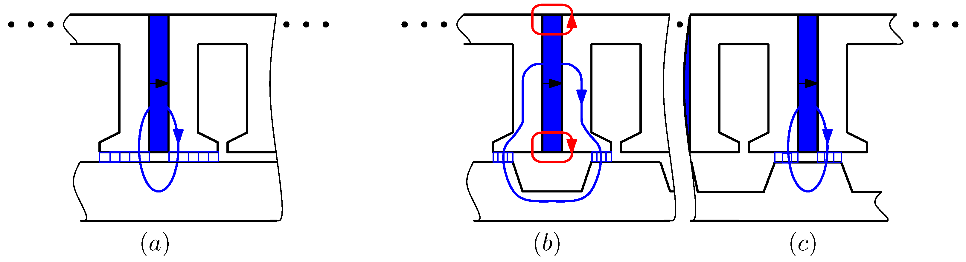
2.3.2. Saturation Correction Function
Referring to Figure 2b,c, one can expect that both rotor and stator teeth will be locally-saturated within the air gap, and specificity in these extreme positions of the rotor will be characterized by similar saturation levels on both sides of the stator tooth.
Except in these particular positions, the two stator tooth sides have different saturation levels, leading to different saturation correction factors. For the sake of their prediction, two sets of tooth side are distinguished: (i) the sides facing the outside of the PMs and (ii) the sides facing inside in the PMs. Consequently, two saturation correction functions, denoted and , have been considered for each stator tooth. These function vary with respect to the tooth spatial position and with the rotor one , as follows:
where are the initial shifts of the two tooth sides.
The analytical prediction of the no-load air gap flux density should take into consideration:
- The nonlinear behavior of the iron due to the magnetic saturation which is commonly accounted for using the B–H curve,
- The deformation of the flux tube within the air gap due to the fringing effect, as illustrated in Figure 3.
Figure 3. Flux tube deformation within the air gap: the fringing effect.
The flux tube deformation caused by the fringing could be accounted for, considering a surface coefficient , which is expressed as:
For a given tooth (j), a correction function is built up considering , as follows:
where:
Finally, the vector of the saturation correction functions, denoted , is expressed as follows:
2.4. Armature Magnetic Reaction
Let us consider a three-phase balanced current supply feeding the armature phases:
where is the rotor speed, and where and are the current maximum value and initial phase.
The Fourier expansions of the resulting MMF spatial repartitions of the armature phases are expressed as:
where is the number of turns per armature coil and where is the normalized armature MMF amplitude:
where is the coil pitch to the armature pole pitch ratio:
Finally, one can formulate the Fourier expansion of the armature magnetic reaction, denoted , as follows:
where is the total permeance:
2.5. Torque Formulation
The developed torque can be formulated as follows:
where and are the electromagnetic and cogging torques, respectively.
Referring to [7], FSPMMs exhibit almost similar direct and quadrature inductances. Hence, their electromagnetic torque is limited to the synchronizing component [18,19]:
where:
- is the equivalent no-load air gap flux density;
- is the active length of the machine;
- is the number of coils per phase;
- is the winding factor;
- and are the permeance correction and leakage flux factors, respectively, [18];
- is the armature current quadrature component.
The cogging torque prediction is based on the co-energy W, which is expressed as:
where V is the volume of the air gap.
The cogging torque is formulated as follows [4]:
3. Case Study
The design parameters and the geometrical ones (identified in Figure 1) of the FSPMM under study are listed in Table 1. The analysis treated hereunder considers two cases: (i) the case where the magnetic saturation is not taken into account and (ii) the case where the magnetic saturation is taken into account.
Table 1.
Design and geometrical parameters of the FSPMM under study.
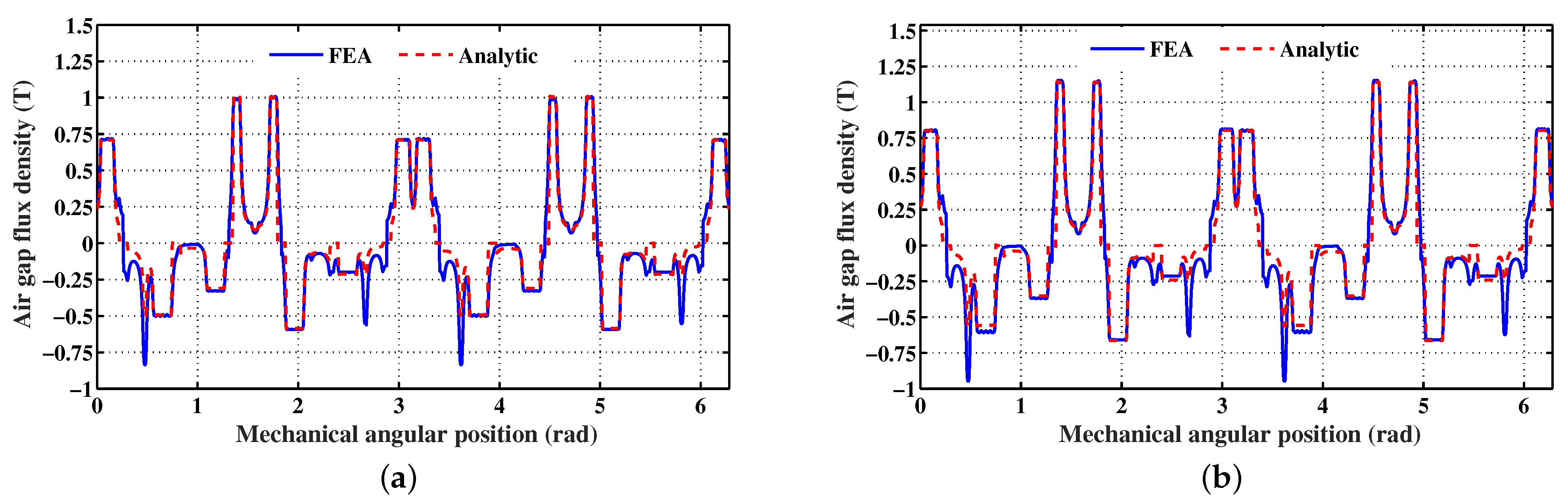
3.1. Analysis Assuming a Linear Magnetic Circuit
The analytical prediction of the flux density created by the PMs in the airgap , with just the stator slotting effect taken into account () and without any correction, led to the spatial repartition illustrated in Figure 4. The same figure shows a 2D FEA validation of the analytically-predicted spatial repartition considering a slottless rotor.
Figure 4.
PM flux density spatial repartition with the stator slotting effect taken into account, assuming a slottless rotor, and without correction.
The analytical prediction of the flux density , with the stator and rotor permeance functions taken into account () and without any correction, led to the spatial repartition illustrated in Figure 5. The same figure shows a 2D FEA prediction of . From the analysis of these results, one can notice remarkable disparities between the analytical and FEA spatial repartitions in some peak values.
Figure 5.
PM flux density spatial repartition with the stator and rotor slotting effects taken into account.
The analytical prediction of the flux density for different positions of the rotor, with the stator and rotor permeance functions and the rotor position correction function taken into account, led to the spatial repartitions illustrated in Figure 6. The same figure shows a 2D FEA validation of the analytically-predicted spatial repartitions. One can notice a good agreement.
Figure 6.
PM flux density spatial repartitions for different rotor positions, with the stator and rotor permeance functions and the rotor position correction function taken into account. Legend: (a) = 0°, (b) = 5.4°, (c) = 12.6°, (d) = 18°, (e) = 23.4°, (f) = 30.6°.
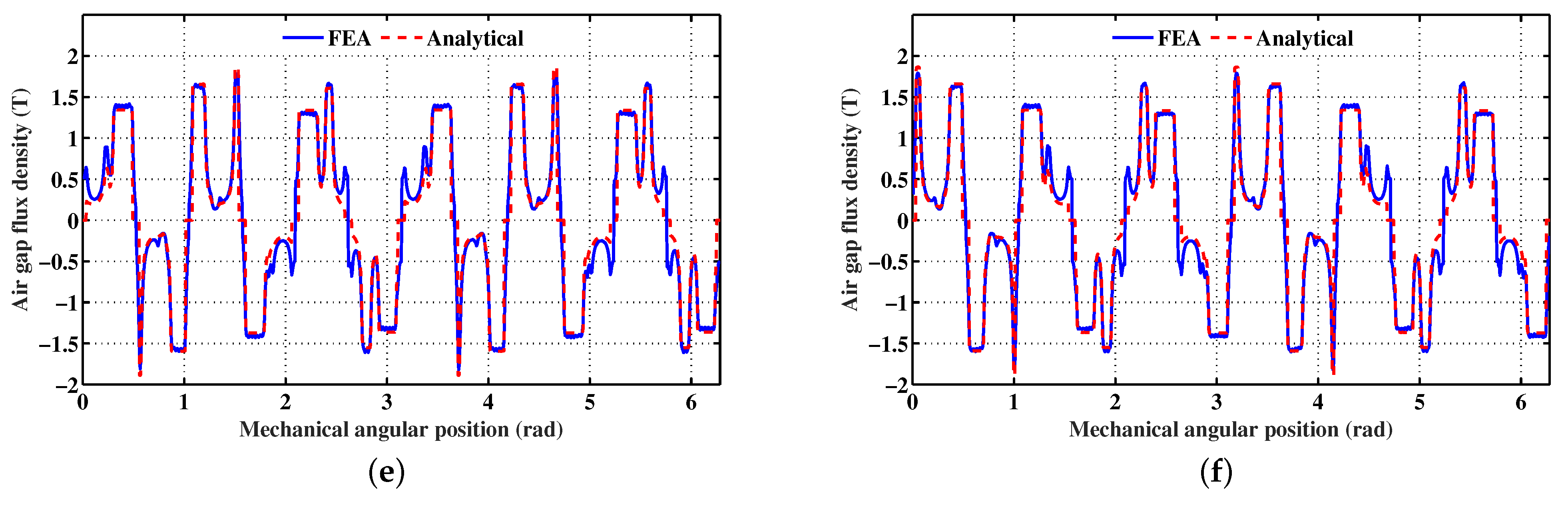
3.2. Analysis with the Magnetic Saturation Taken into Account
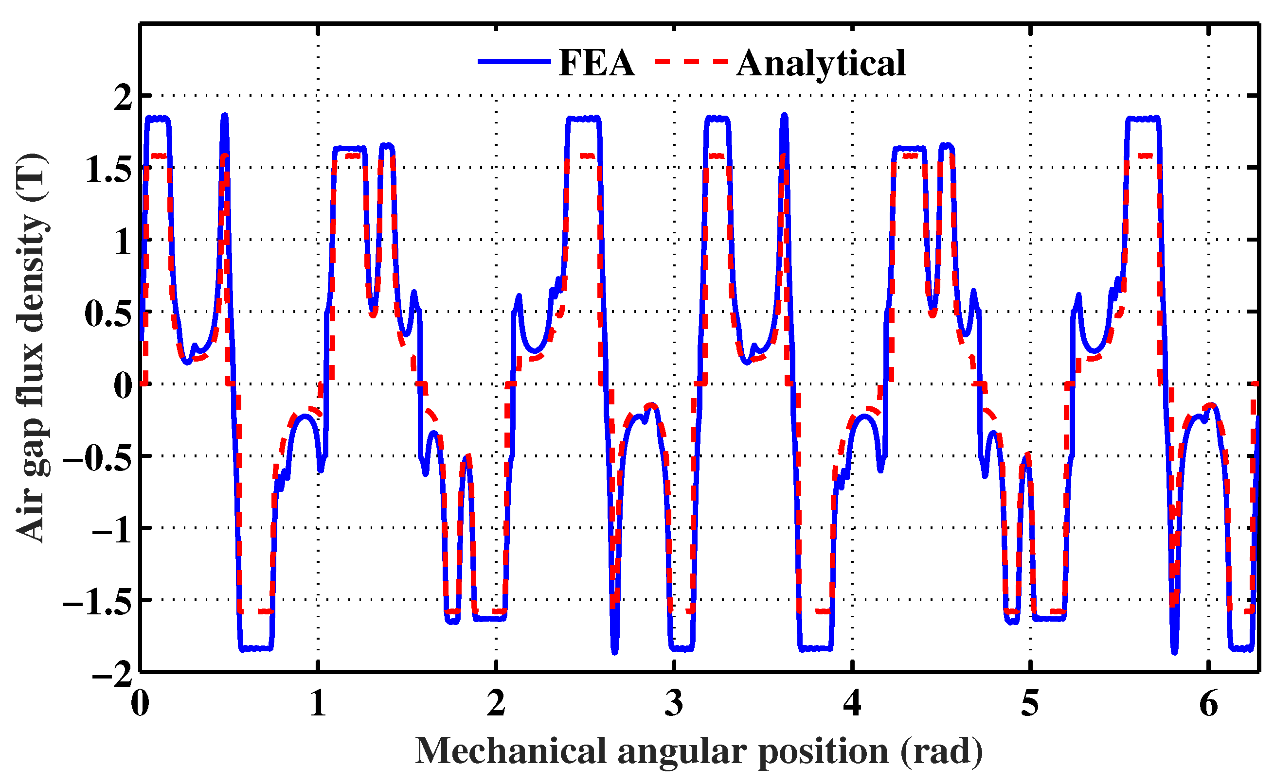
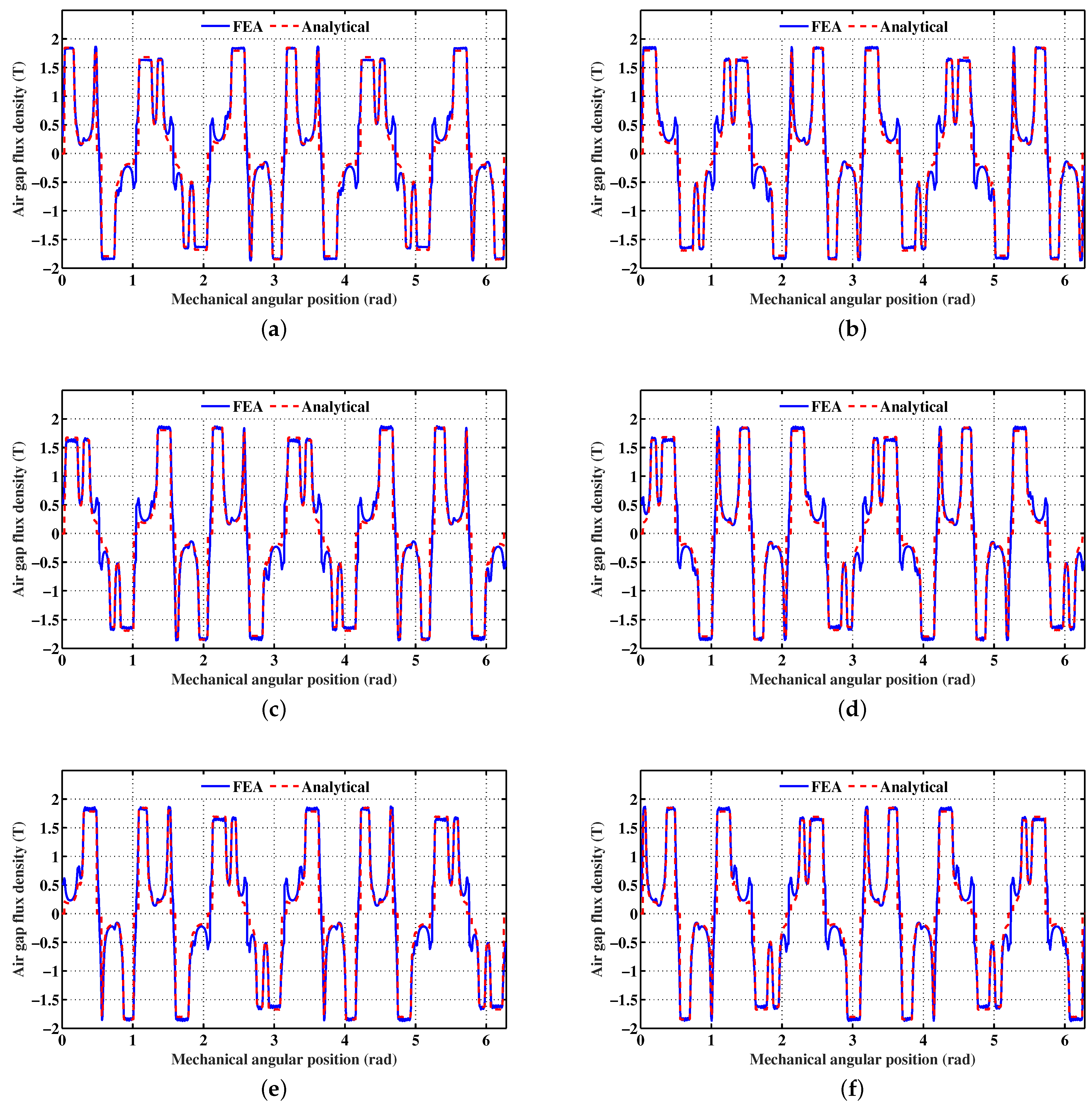
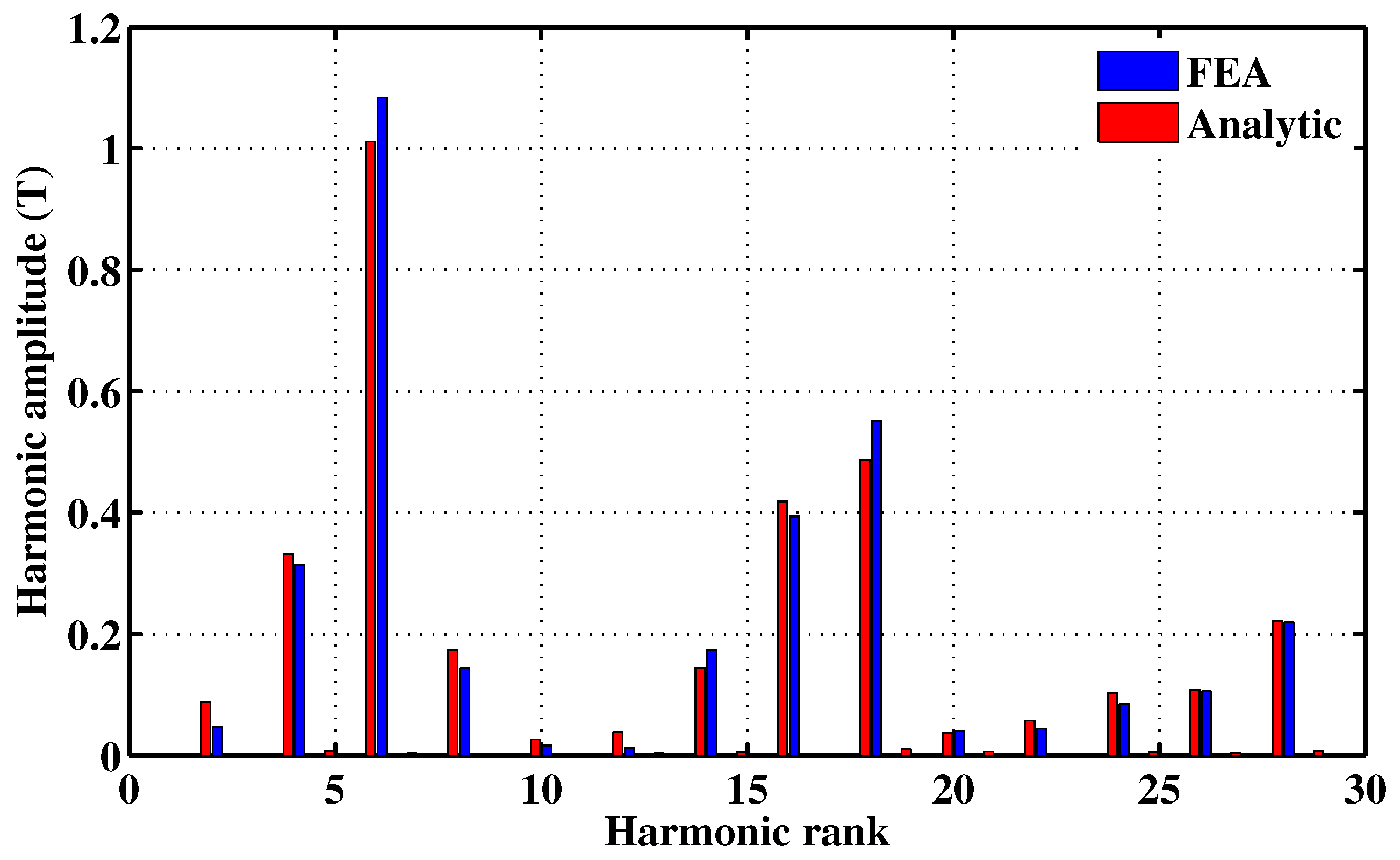
3.2.1. PM Air Gap Flux Density
The analytical prediction of the flux density , with the stator and rotor permeance functions and the rotor position correction function taken into account and without the saturation correction, led to the spatial repartition illustrated in Figure 7. The same figure shows a 2D FEA prediction of with the magnetic saturation taken into consideration. From then analysis of these results, one can notice remarkable differences between some amplitudes of the analytical and FEA spatial repartitions.
Figure 7.
PM flux density spatial repartitions with the stator and rotor slotting effects and the rotor position correction taken into account: (analytic) without saturation correction, (FEA) B–H curve implemented.
The analytical prediction of the flux density for different positions of the rotor, with the stator and rotor permeance functions and the rotor position and saturation corrections taken into account, led to the spatial repartitions illustrated in Figure 8. The same figure shows a 2D FEA validation of the analytically-predicted flux density spatial repartitions. One can notice good agreement. This statement is confirmed by the spectra shown in Figure 9, corresponding to the FFT of the analytically- and FEA-predicted shown in Figure 8a.

Figure 8.
PM flux density spatial repartitions for different rotor positions, with the stator and rotor permeance functions and the rotor position and saturation corrections taken into account. Legend: (a) = 0°, (b) = 5.40°, (c) = 12.6°, (d) = 18°, (e) = 23.4°, (f) = 30.6°.
Figure 9.
Spectra corresponding to the FFT of the analytically- and FEA-predicted shown in Figure 8a.
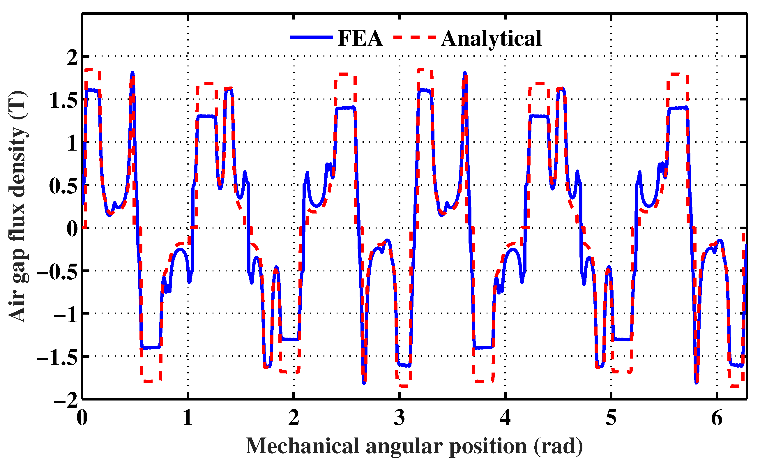
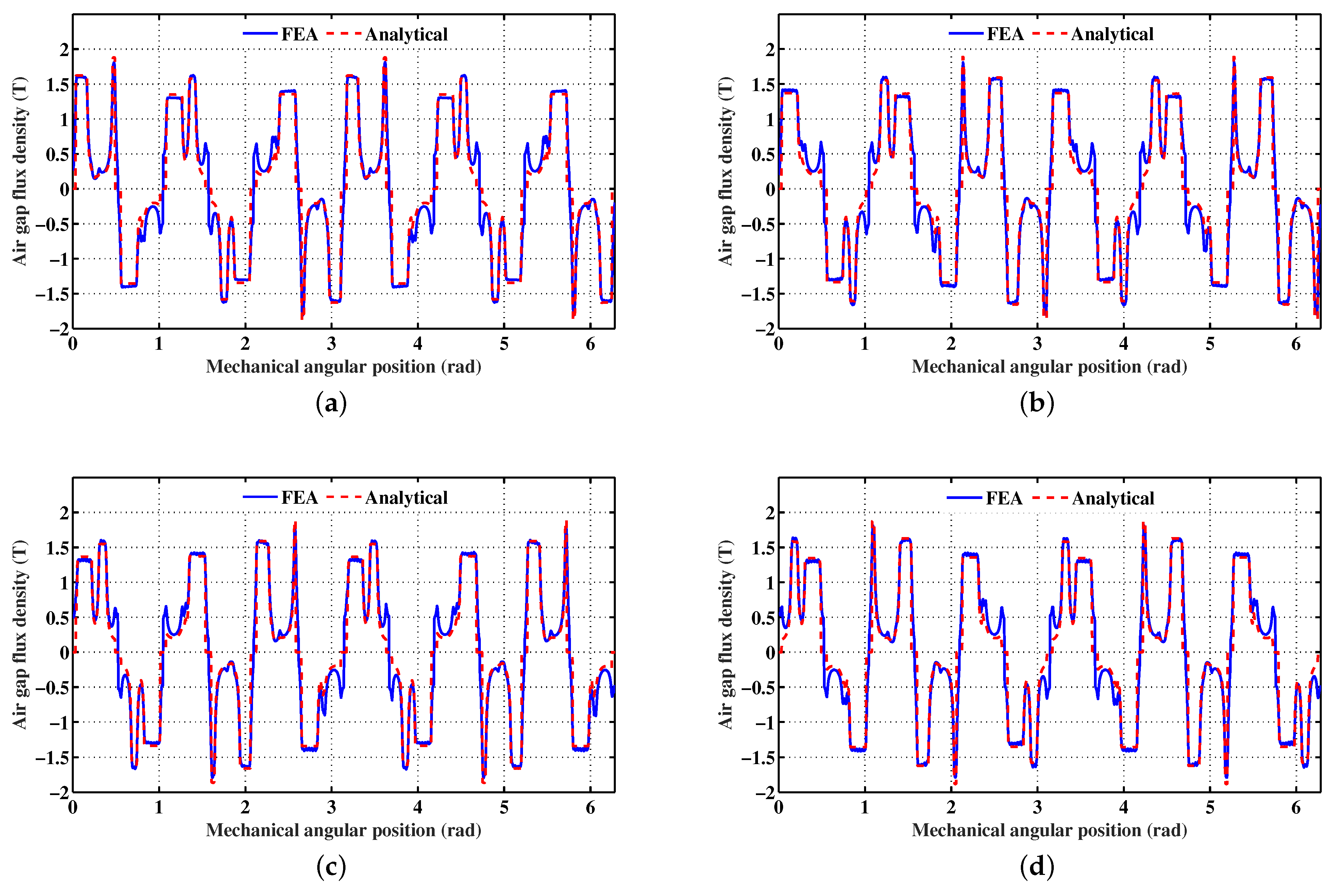
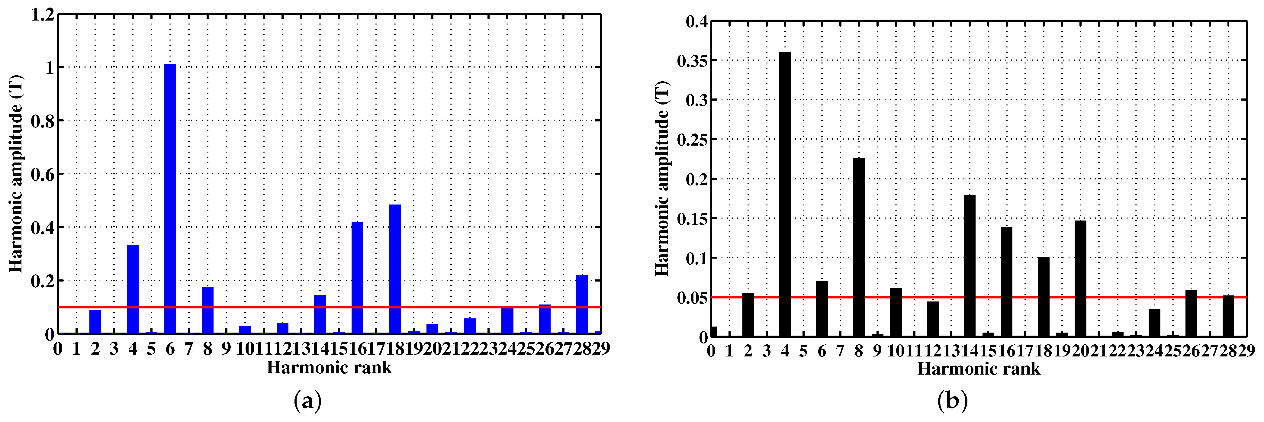
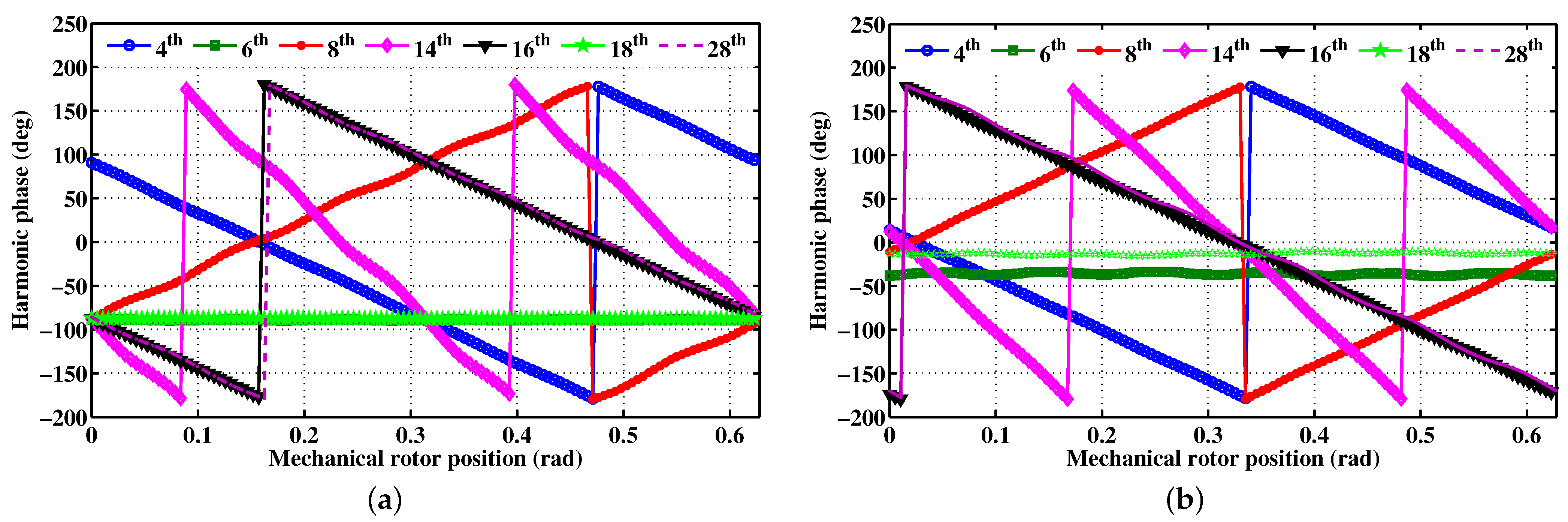
3.2.2. Armature Magnetic Reaction
The FSPMM under study is characterized by , which leads to the following normalized armature MMF amplitude:
Figure 10 illustrates the analytically-predicted spatial repartitions of the armature magnetic reaction for two maximum values of the armature current such that (a) = 3.6 A and (b) = 4.8 A, and for the initial rotor position ( = 0°). The same figure shows a 2D FEA validation of the analytical results where the PM material has been changed to air. One can notice an acceptable agreement which confirms the effectiveness of the analytical formulation of the armature magnetic reaction thanks to the considered stator and rotor permeance functions and the introduced correction functions.
Figure 10.
Analytically- and FEA-predicted spatial repartitions of the armature magnetic reaction for = 0°. Legend: (a) = 3.6 A, (b) = 4.8 A.
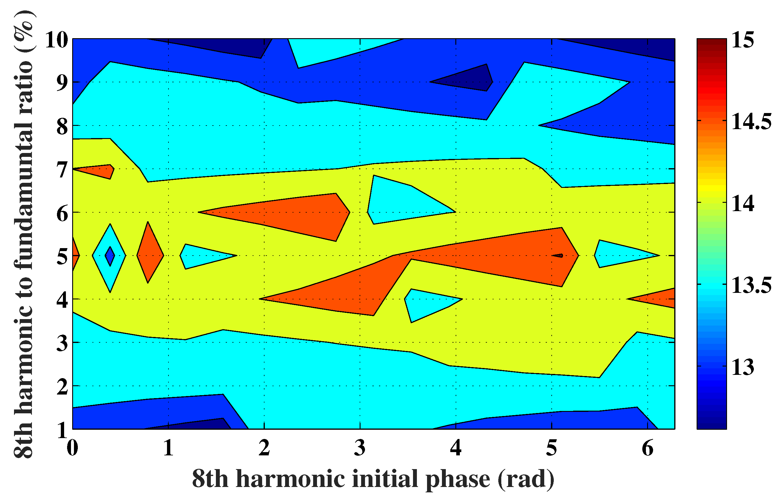
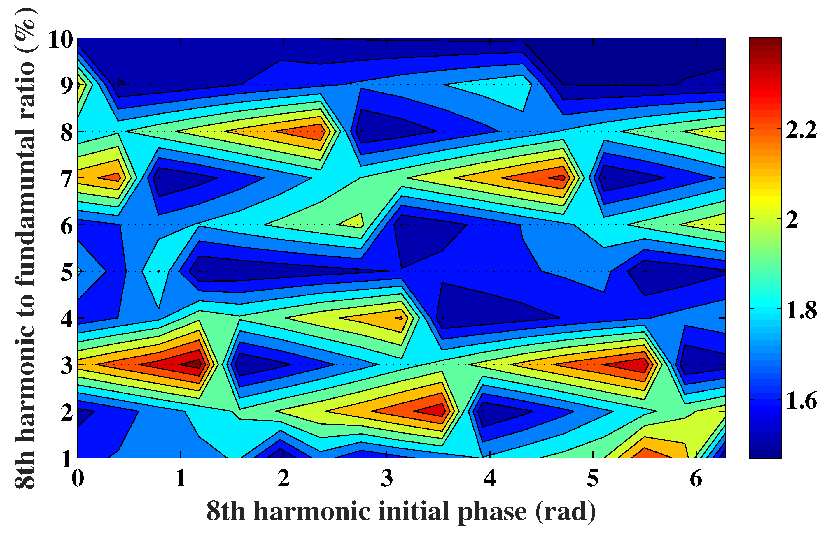
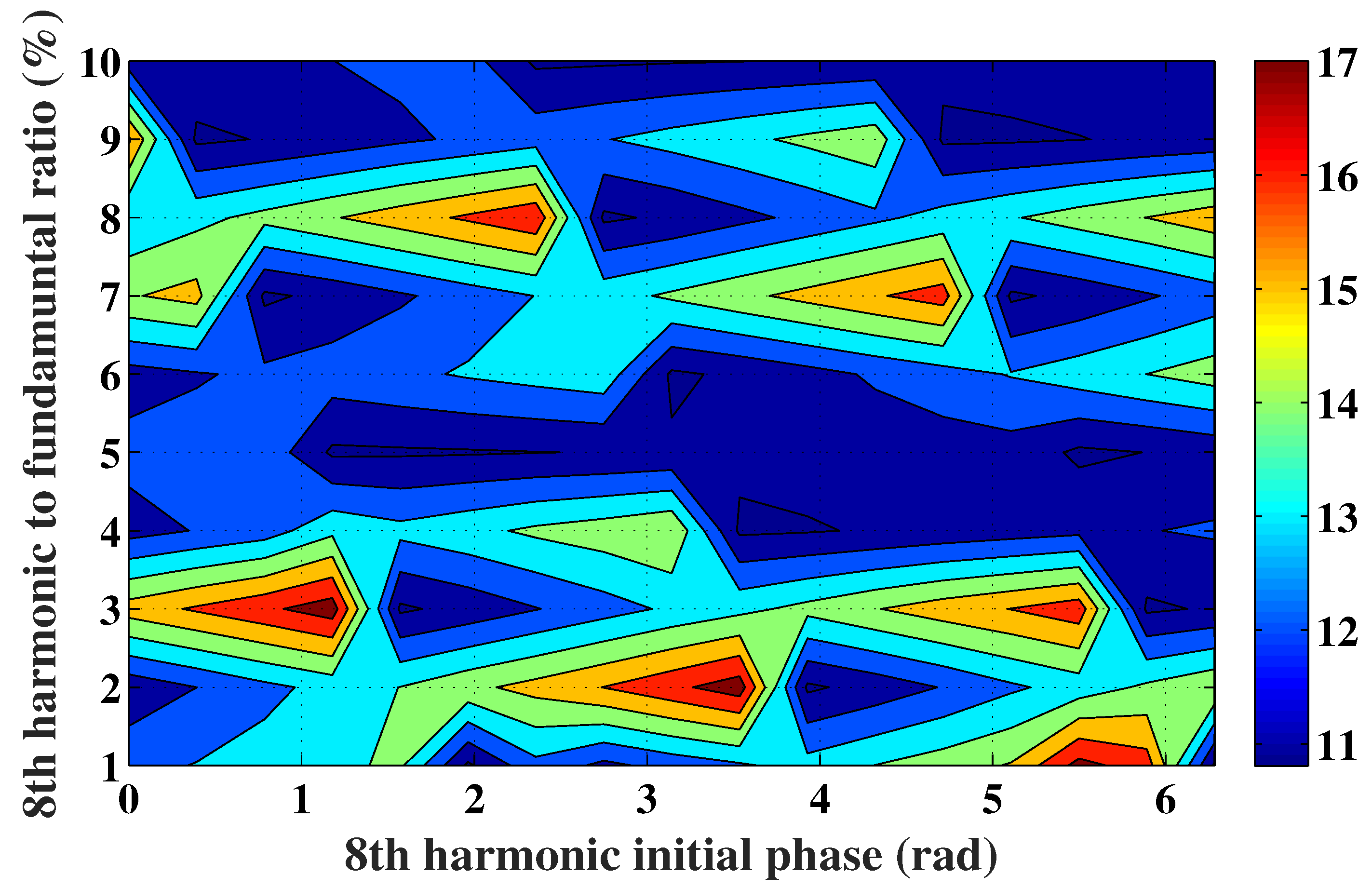
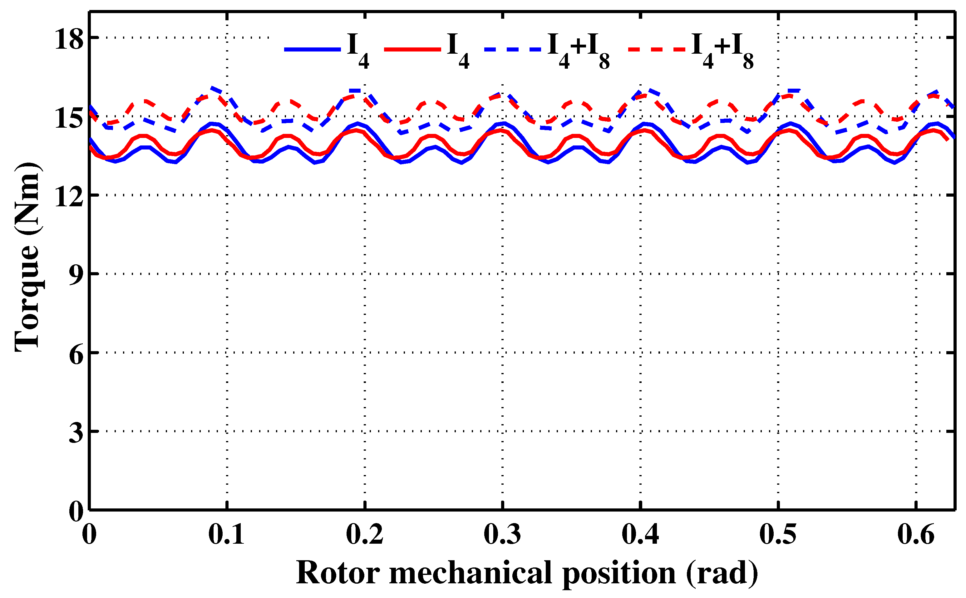
3.2.3. Torque Production Enhancement
Basically, in smooth pole AC machines, the torque results from the synchronization between a rotating magnetic field (RMF) created by the stator and a RMF created by the rotor. In emerging AC machines such as FSPMMs, the torque production condition is achieved by several harmonics.
In the case of the studied machine, this statement is confirmed by the spectra depicted in Figure 11. Considering the dominant harmonics, the variations in their phases with respect to the rotor position are illustrated in Figure 12. One can distinguish three types of RMF dominant harmonics involved in torque production according to their rotation, as classified in Table 2. The analysis of the later reveals that the harmonic of rank 8 behaves as a load torque.
Figure 11.
Spectrum of the spatial repartition of the analytically-predicted flux density at = 0°. (a) Flux density created by the PMs, (b) armature magnetic reaction.
Figure 12.
Phases of the dominant harmonics of the spatial repartition of the analytically-predicted flux density versus the rotor position. (a) Harmonics of the flux density created by the PMs, (b) harmonics of the armature magnetic reaction.
Table 2.
RMF-dominant harmonics contributing to torque of the FSPMM under study.
In order to cancel the negative contribution to torque of the harmonic of rank 8, a three phase current supply with an harmonic frequency equal to twice the one of the fundamental, is injected in the armature. Beyond the angular frequency, the amplitude and the initial phase of the injected 8th harmonic current were varied in an attempt to select a combination that optimizes the developed torque, as illustrated in the mappings of Figure 13, Figure 14 and Figure 15.
Figure 13.
Mapping of the mean total torque developed following the injection of an harmonic current of rank 8, plotted in the plane (8th harmonic initial phase, 8th harmonic amplitude to fundamental amplitude ratio).
Figure 14.
Mapping of the ripple of the total torque developed following the injection of an harmonic current of rank 8, plotted in the same plane as Figure 13.
Figure 15.
Mapping of the ripple to mean value ratio of the total torque developed following the injection of an harmonic current of rank 8, plotted in the same plane as Figure 13.
Referring to Figure 13, it clearly appears that the combination characterized by an 8th harmonic initial phase of and an 8th harmonic amplitude to fundamental amplitude ratio of 5% yields the highest mean torque. Moreover, Figure 14 shows that this combination exhibits a low torque ripple.
The analytical prediction of the torque-angle characteristic was carried out for = 3.6 A and for the combination characterized by an 8th harmonic initial phase of and an 8th harmonic amplitude to fundamental amplitude ratio of 5%. The obtained results are shown in Figure 16. The same figure also shows the torque-angle characteristic predicted with the FSPMM fed by just the fundamental current of rank 4.
Figure 16.
Torque-angle characteristics for a peak fundamental current of 3.6 A. Legend 1: (continuous line) armature current supply limited to the fundamental of rank 4; (interrupted line) armature current supply including both the fundamental of rank 4 and the harmonic of rank 8, such that the 8th harmonic initial phase is equal to and the 8th harmonic amplitude to fundamental amplitude ratio is equal to 5%. Legend 2: (red) analytical results, (bleu) FEA results.
For the sake of validation, Figure 16 gives the FEA-predicted torque-angle characteristics corresponding to the two cases: (i) armature phases fed by currents incorporating the fundamental of rank 4 and the harmonic of rank 8, and (ii) armature phases fed by currents incorporating a single angular frequency equal to the fundamental of rank 4.
From the characteristics illustrated in Figure 16, one can deduce the torque mean value and ripple ratio (ripple peak-to-peak value over the mean value). These are classified in Table 3. One can notice that the injection of harmonic currents of rank 8 yields an increase in the torque mean value of almost 9%.
Table 3.
Comparison of the analytically- and FEA-predicted torque-angle characteristics with and without injection of harmonic currents of rank 8.
4. Conclusions
Thanks to their passive and robust rotors, FSPMMs could suitably equip EPS systems. From this perspective, we proposed a simple approach to improve the torque production capabilities of FSPMMs in an attempt to meet the EPS requirements. It consists of injecting harmonic currents generating torque components that cancel the ones acting as brakes among those resulting from the fundamental current.
To do so, special attention has been paid to the formulation of the air gap flux density spatial distribution. The analytical study was initiated by the derivation of the air gap flux density generated by the stator PMs neglecting the slotting effect. Then, the latter and the saliency caused by the PM concentrating flux arrangement were taken into account through the incorporation of stator and rotor permeance functions. Moreover, the accuracy of the predicted flux density spatial repartition was improved using two dedicated correction functions that take into account the rotor position and the magnetic saturation. The analytical prediction of the air gap flux density spatial distribution was achieved with the incorporation of the armature magnetic reaction.
This done, the RMF dominant harmonics were identified using the spectra of the air gap flux density generated by the PMs and by the armature magnetic reaction, for a given rotor position. It was found that the torque production condition is fulfilled by several harmonics, and one among them behaves as a load torque. In order to cancel out the negative contribution of such a harmonic and then enhance the torque production, a current supply having the same harmonic frequency was injected. In spite of the simplicity of the proposed approach, it has been found that an almost 9% increase in the mean torque could be gained if appropriate amplitude and initial phase of the injected harmonic current are selected. With that said, the authors believe that there is still some way to go before FSPMMs could be regarded as mature technology for EPS systems.
Author Contributions
Conceptualization, A.S., I.A. and A.M.; methodology, A.S., I.A. and A.M.; validation, A.A., A.S. and I.A.; formal analysis, A.S., I.A. and A.M.; investigation, A.A., A.S., I.A. and A.M.; resources, A.M. data curation, A.A., A.S. and I.A.; writing—original draft preparation, A.S., I.A. and A.M.; writing—review and editing, A.M.; visualization, A.S. and I.A.; supervision, A.M.; project administration, I.A.; funding acquisition, A.M., All authors have read and agreed to the published version of the manuscript.
Funding
This research was funded by the Tunisian Ministry of Higher Education and Scientific Research, under grant number LR13ES24.
Institutional Review Board Statement
Not applicable.
Informed Consent Statement
Not applicable.
Data Availability Statement
Not applicable.
Conflicts of Interest
The authors declare no conflict of interest.
References
- Rauch, S.E.; Johnson, L.J. Design principles of flux-switch alternators [includes discussion]. Trans. Am. Inst. Electr. Eng. Part III Power Appar. Syst. 1955, 74, 1261–1268. [Google Scholar] [CrossRef]
- Hua, W.; Cheng, M.; Zhu, Z.Q.; Howe, D. Analysis and optimization of back EMF waveform of a flux-switching permanent magnet motor. IEEE Trans. Energy Convers. 2008, 23, 727–733. [Google Scholar] [CrossRef]
- Gysen, B.L.J.; Ilhan, E.; Meessen, K.J.; Paulides, J.J.H.; Lomonova, E.A. Modeling of flux switching permanent magnet machines with Fourier analysis. IEEE Trans. Magn. 2010, 46, 1499–1502. [Google Scholar] [CrossRef] [Green Version]
- Wang, D.; Wang, X.; Jung, S.-Y. Reduction on cogging torque in flux-switching permanent magnet machine by teeth notching schemes. IEEE Trans. Magn. 2012, 48, 4228–4231. [Google Scholar] [CrossRef]
- Yan, J.; Lin, H.; Feng, Y.; Zhu, Z.Q.; Jin, P.; Guo, Y. Cogging torque optimization of flux-switching transverse flux permanent magnet machine. IEEE Trans. Magn. 2013, 49, 2169–2172. [Google Scholar] [CrossRef]
- Wu, Z.Z.; Zhu, Z.Q. Analysis of air-gap field modulation and magnetic gearing effects in switched flux permanent magnet machines. IEEE Trans. Magn. 2015, 51, 8105012. [Google Scholar] [CrossRef]
- Zeng, Z.; Shen, Y.; Lu, Q.; Gerada, D.; Wu, B.; Huang, X.; Gerada, C. Flux-density harmonics analysis of switched-flux permanent magnet machines. IEEE Trans. Magn. 2019, 55, 8103607. [Google Scholar] [CrossRef]
- Zhao, W.; Pan, X.; Ji, J.; Xu, L.; Zheng, J. Analysis of PM eddy current loss in four-phase fault-tolerant flux-switching permanent-magnet machines by air-gap magnetic field modulation theory. IEEE Trans. Ind. Electron. 2020, 67, 5369–5378. [Google Scholar] [CrossRef]
- Hu, J.; Liu, F.; Li, Y. An improved sub-domain model of flux switching permanent magnet machines considering harmonic analysis and slot shape. IEEE Access 2021, 9, 55260–55270. [Google Scholar] [CrossRef]
- Zhu, H.; Xu, Y. Permanent magnet parameter design and performance analysis of bearingless flux switching permanent magnet motor. IEEE Trans. Ind. Electron. 2020, 68, 4153–4163. [Google Scholar] [CrossRef]
- Wu, Z.; Zhu, Z.Q.; Wang, C.; Hua, W.; Wang, K.; Zhang, W. Influence of rotor iron bridge position on DC-winding-induced voltage in wound field switched flux machine having partitioned stators. Chin. J. Electr. Eng. 2021, 7, 20–28. [Google Scholar] [CrossRef]
- Chen, C.; Ren, X.; Li, D.; Qu, R.; Liu, K.; Zou, T. Torque performance enhancement of flux-switching permanent magnet machines with dual sets of magnet arrangements. IEEE Trans. Transp. Electrif. 2021, 7, 2623–2634. [Google Scholar] [CrossRef]
- Bianchi, N.; Pre, M.D.; Bolognani, S. Design of a fault-tolerant IPM motor for electric power steering. IEEE Trans. Veh. Technol. 2006, 55, 1102–1111. [Google Scholar] [CrossRef]
- Saha, S.; Kim, S.-A.; Cho, Y.-H. Optimal Rotor shape design for minimizing cogging torque of spoke type BLAC motor for EPS. In Proceedings of the 2015 IEEE 10th Conference on Industrial Electronics and Applications (ICIEA), Auckland, New Zealand, 15–17 June 2015; pp. 1313–1318. [Google Scholar]
- Liu, C.-T.; Hwang, C.-C.; Chiu, Y.-W. Design of a coaxially magnetic-geared linear actuator for electric power steering system applications. IEEE Trans. Ind. Appl. 2017, 53, 2401–2408. [Google Scholar] [CrossRef]
- Park, H.-J.; Lim, M.-S.; Lee, C.-S. Magnet shape design and verification for SPMSM of EPS system using cycloid curve. IEEE Access 2019, 7, 137207–137216. [Google Scholar] [CrossRef]
- Yang, H.; Ademi, S.; Paredes, J.; McMahon, R.A. Comparative study of motor topologies for electric power steering system. In Proceedings of the 2021 IEEE Workshop on Electrical Machines Design, Control and Diagnosis (WEMDCD), Modena, Italy, 8–9 April 2021. [Google Scholar]
- Chaen, J.T.; Zhu, Z.Q. Winding configurations and optimal stator and rotor pole combination of flux-switching PM brushless AC Machines. IEEE Trans. Energy Convers. 2010, 25, 293–302. [Google Scholar] [CrossRef]
- Abdelkefi, A.; Souissi, A.; Abdennadher, I. Analytical based enhancement of the torque production capability of flux switching PM machines. In Proceedings of the Fourteenth International Conference on Ecological Vehicles and Renewable Energies (EVER), Monaco, Monte-Carlo, 8–10 May 2019; pp. 1–6. [Google Scholar]
Publisher’s Note: MDPI stays neutral with regard to jurisdictional claims in published maps and institutional affiliations. |
© 2022 by the authors. Licensee MDPI, Basel, Switzerland. This article is an open access article distributed under the terms and conditions of the Creative Commons Attribution (CC BY) license (https://creativecommons.org/licenses/by/4.0/).