1. Introduction
Due to high torque density and high efficiency, permanent magnet (PM) machines have gained extensive attention recently. Amongst the conventional PM machines, interior PM (IPM) machines are regarded as popular choices for electric vehicles [
1,
2]. In order to improve the reluctance torque (RT) component, PM-assisted synchronous reluctance machines (PM-SynRMs) are extensively investigated in [
3,
4,
5]. However, the conventional IPM machines suffer from a compromised utilization ratio of magnet torque (MT) and RT components, whose optimal current angles differ by 45 electrical degrees theoretically. In order to deal with this issue, dual rotor [
6], hybrid rotor [
7,
8], and asymmetrical PM-SynRMs [
4,
9] were developed in recent years. However, the former two machines have relatively complicated structure and the latter one suffers from significant flux leakage as well as sophisticated magnetic flux paths.
The purpose of this paper is to propose a magnet axis shifted (MAS) IPM (MAS-IPM) machine with an asymmetrical PM arrangement, which aims to improve the torque component utilization ratio, and hence the torque density. In this paper, the configuration and the operating principle of the proposed machine are described. The effects of the PM asymmetry ratio on the torque performance are evaluated, and the design parameters are optimized to improve the torque capability. In order to validate the MAS effect of the proposed asymmetrical PM arrangement, the major electromagnetic characteristics of the optimal MAS-IPM machine are analyzed and compared with those of the Prius 2010 IPM machine (Toyota Motor Corporation, Tokyo, Japan) by finite element method (FEM).
2. Machine Configuration and Basic Principle
The configurations of the Prius 2010 IPM machine and the proposed MAS-IPM machine are shown in
Figure 1a,b, respectively. For a fair comparison, the two machines share the same stator structure, active stack length, air gap length, current density and PM usages, as shown in
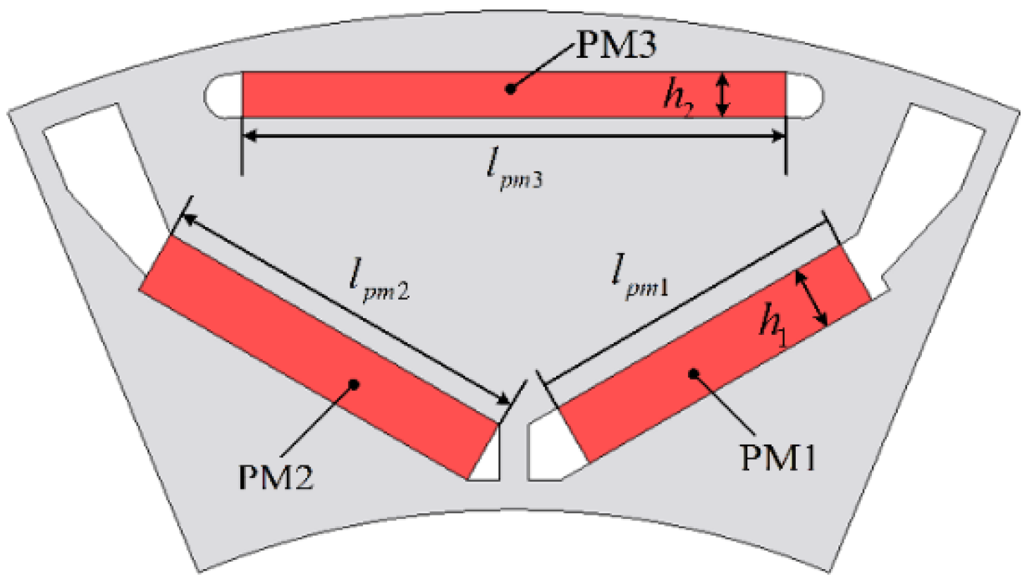
Table 1. The main feature of the MAS-IPM machine refers to an asymmetrical “▽”-shaped PM rotor structure, in which the lengths of the second-layer two PMs are unequal to achieve the MAS effect.
For the conventional IPM machine, the optimal current angles
βPM and
βR when the MT and RT components reach their peak values are different, the difference of which is expressed as
In the traditional IPM machine with a symmetrical rotor configuration, as we know, the current angle difference γs is theoretically an electrical angle of 45. On the other hand, in the proposed machine, since the magnet axis is shifted towards the reluctance axis due to the asymmetrical PM arrangement, the difference of the current angles γs can be significantly reduced, which can further improve the torque capability.
The no-load magnetic fields of the two machines for comparison are plotted in
Figure 2. It can be seen that the magnet
d-axis is shifted by an angle in the proposed MAS-IPM machine, while the reluctance
d-axis remains unchanged. It means that the magnet and reluctance axes become closer compared with the Prius 2010 machine. As a result, the difference of the current angles
γs of the proposed machine can be reduced and the corresponding total torque is improved, confirming the feasibility of the MAS effect.
3. Optimization of The Proposed MAS-IPM Machine
In order to maximize the torque capability by effectively employing the proposed MAS effect, some design variables are selected to be optimized, as shown in
Figure 3. The peak current 246 A was used for obtaining the maximum torque, which is accordance with that of Prius 2010 machine. A coefficient
α is defined as
lpm1/
lpm2 to describe the asymmetry level of PM1 and PM2, which is associated with the MAS effect. The design global optimization is performed by a multi-objective genetic algorithm with the constraints of the overall sizing, e.g., stator outer diameter and stack length, as shown in
Table 1. The optimization target is to maximize the average torque and minimize the torque ripple, the corresponding weight factors of which are 1 and 0.5, respectively. In addition, the major design parameters of the optimized IPM machines and their variation ranges are presented in
Table 2.
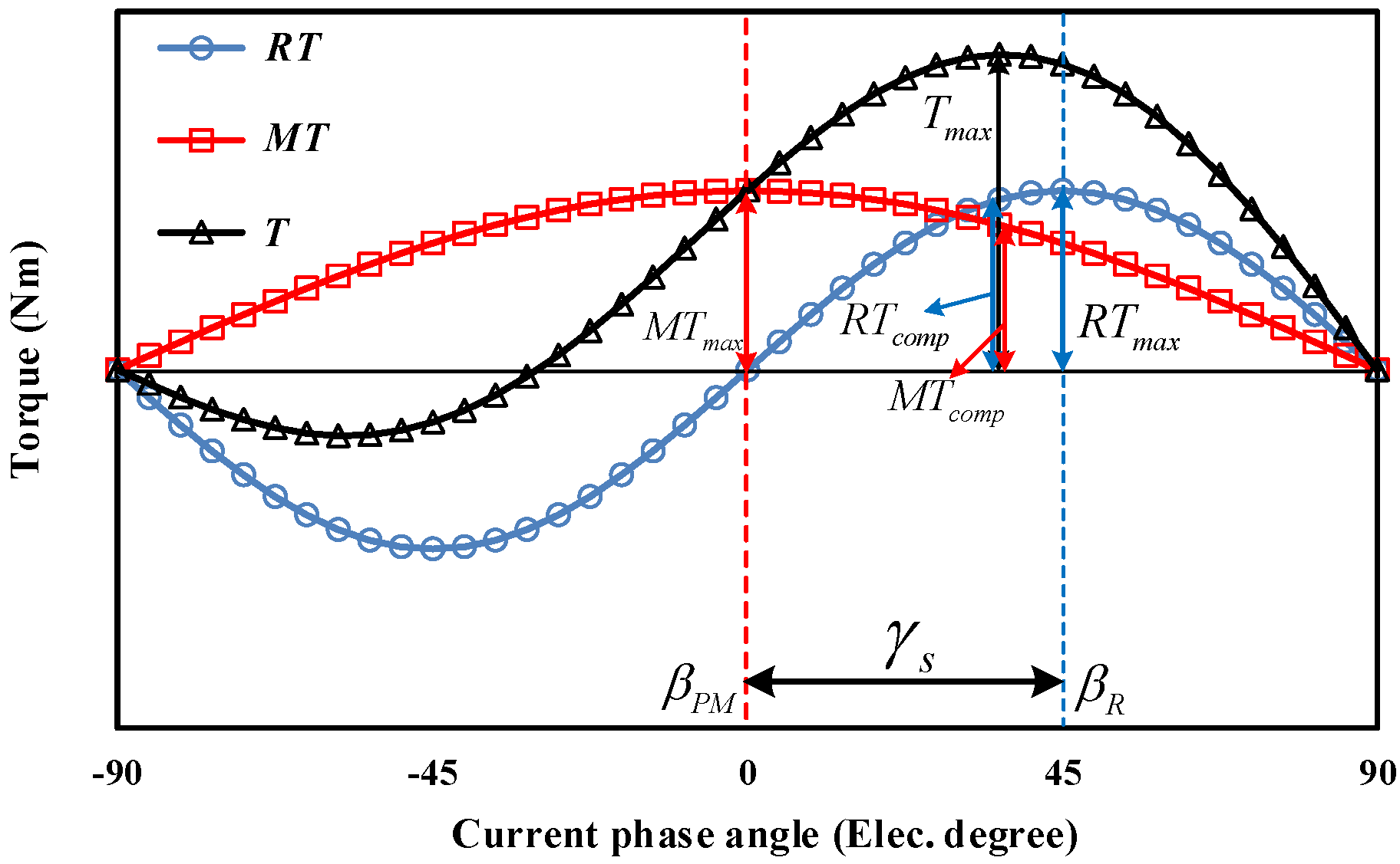
For illustrating the definition of the torque component utilization ratio, the diagram for the torque separation of a conventional IPM machine is shown in
Figure 4. The torque component utilization ratios of the
MT and
RT upm and
ur are defined as follows
where
MTcomp and
RTcomp are
MT and
RT when the total torque reaches the peak value, and
MTmax and
RTmax denote their maximum values of
MT and
RT.
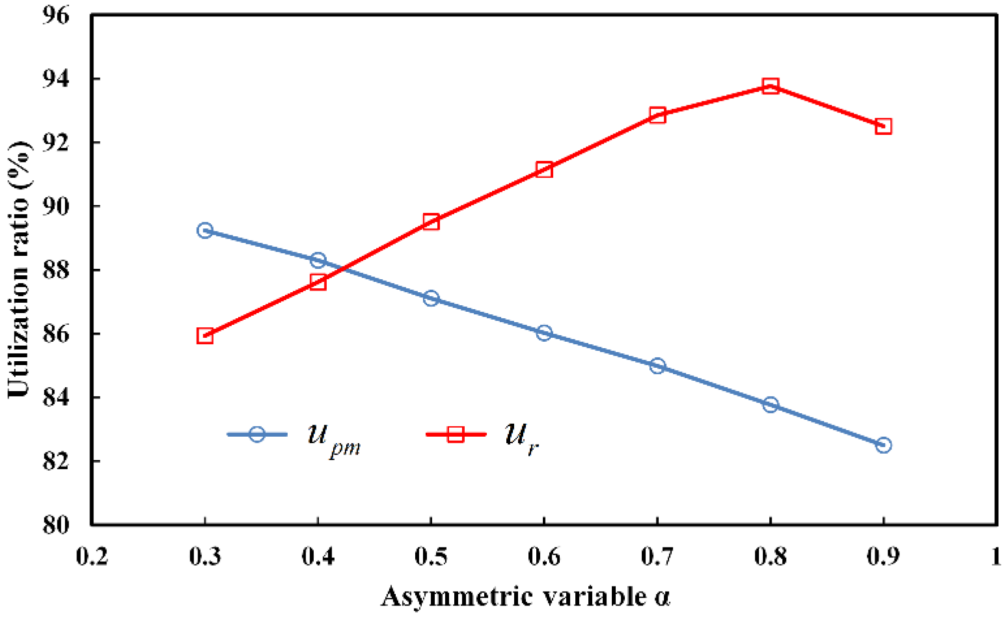
A preliminary model is obtained based on the global optimization. To better illustrate the influence of
α on torque performance, the single parameter optimization is performed. The torque component utilization ratios of
MT and
RT as functions of different asymmetry coefficients
α are presented in
Figure 5. With the increment of
α, the
RT utilization ratio
ur is increasing proportionally until
α reaches 0.8, where
ur reaches the peak value of 93.77%. At the same time, the
MT utilization ratio
upm decreases with the increase in
α, which is attributed to the weakening of the MAS effect in that case. Nevertheless,
Figure 6 shows the toque component variation with the asymmetry coefficient. It shows that the total torque and the
MT component can be improved with the increment of
α until it reaches 0.8. The improvement in the
MT component can be explained by the increase in PM usage, despite
upm decreasing. The
RT component is almost invariant because the rotor steel lamination remains unchanged.
After the optimization, the optimal asymmetrical structure is confirmed. The optimized design parameters of the proposed MAS-IPM machine are obtained, i.e., h1 = 3.9 mm, h2 = 2.7 mm, lpm1 = 18.4 mm, lpm2 = 23 mm, lpm3 = 33 mm, and α = 0.8.
4. Performance Comparison
4.1. No-Load Performance
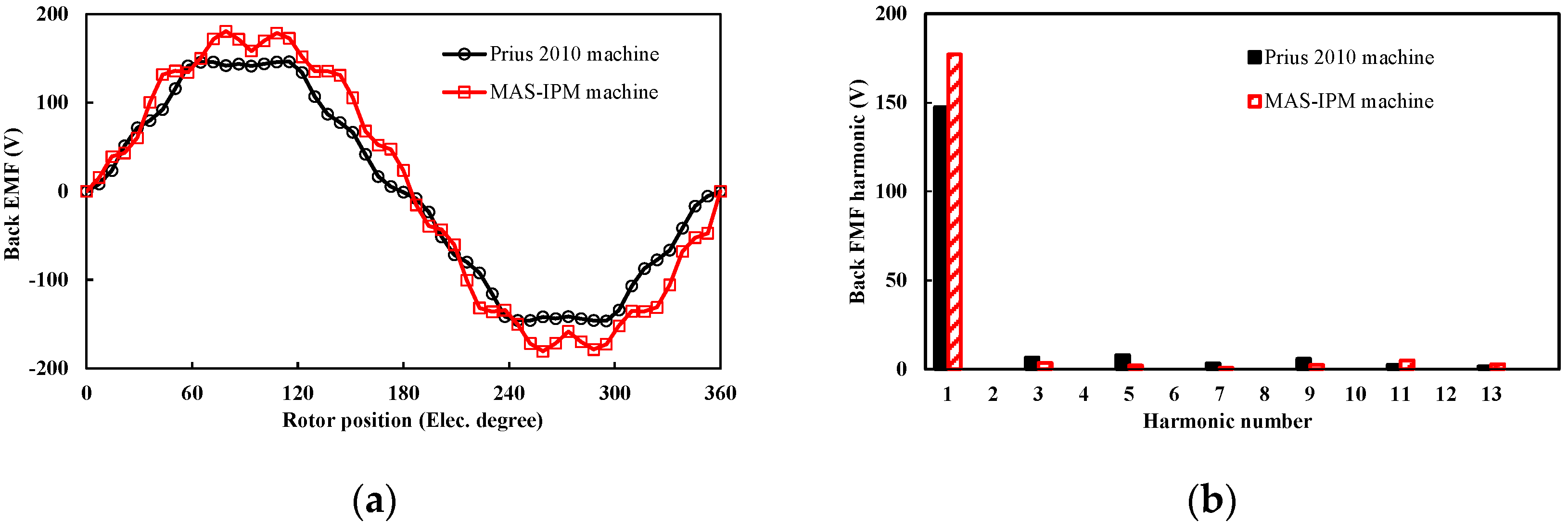
The back-EMFs at rated speed of the two investigated machines are shown in
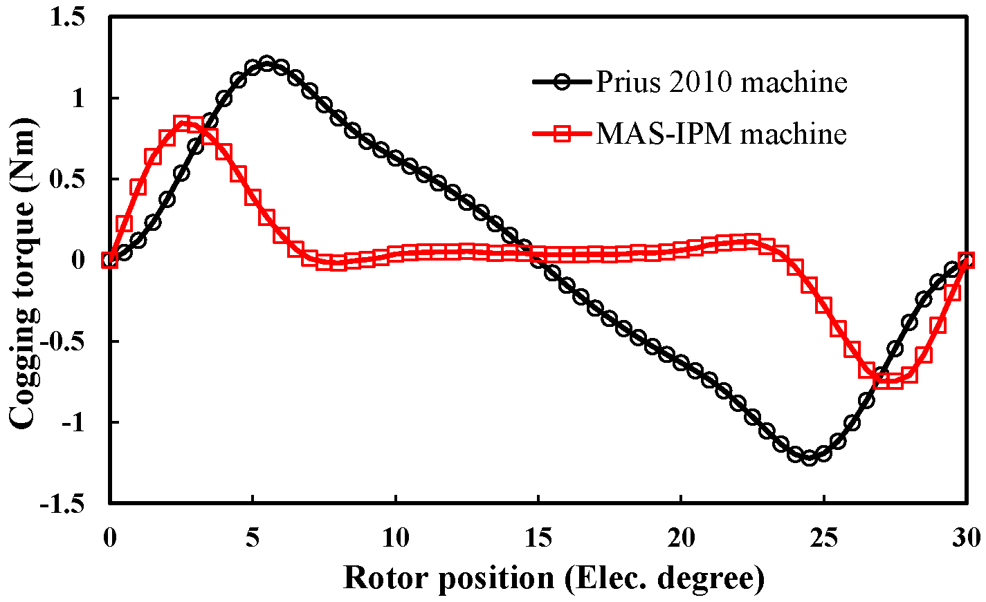
Figure 7. It can be found that the root-mean-square (RMS) EMF of the proposed machine is 20.2% higher than that of the Prius machine. Meanwhile, it shows that the MAS-IPM machine exhibits better sinusoidal back-EMF than the conventional machine. The cogging torque waveforms are illustrated in
Figure 8. It can be seen that the Prius 2010 machine exhibits higher cogging torque than the MAS-IPM machine. This is mainly attributed to lower THD of the back-EMF of the proposed MAS-IPM machine.
4.2. Torque Characteristics
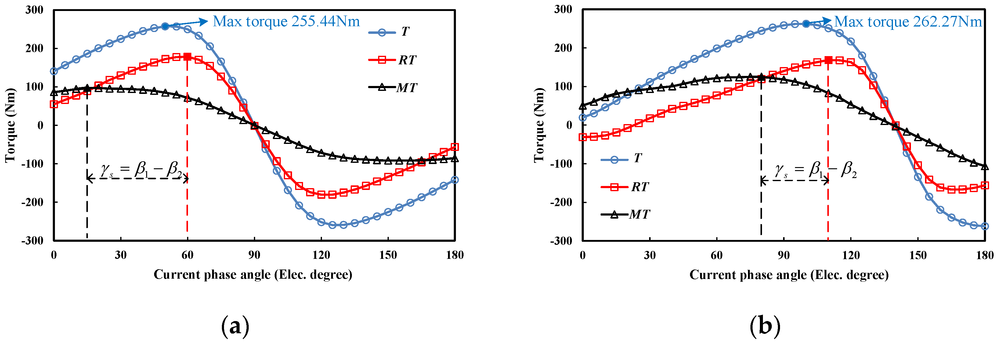
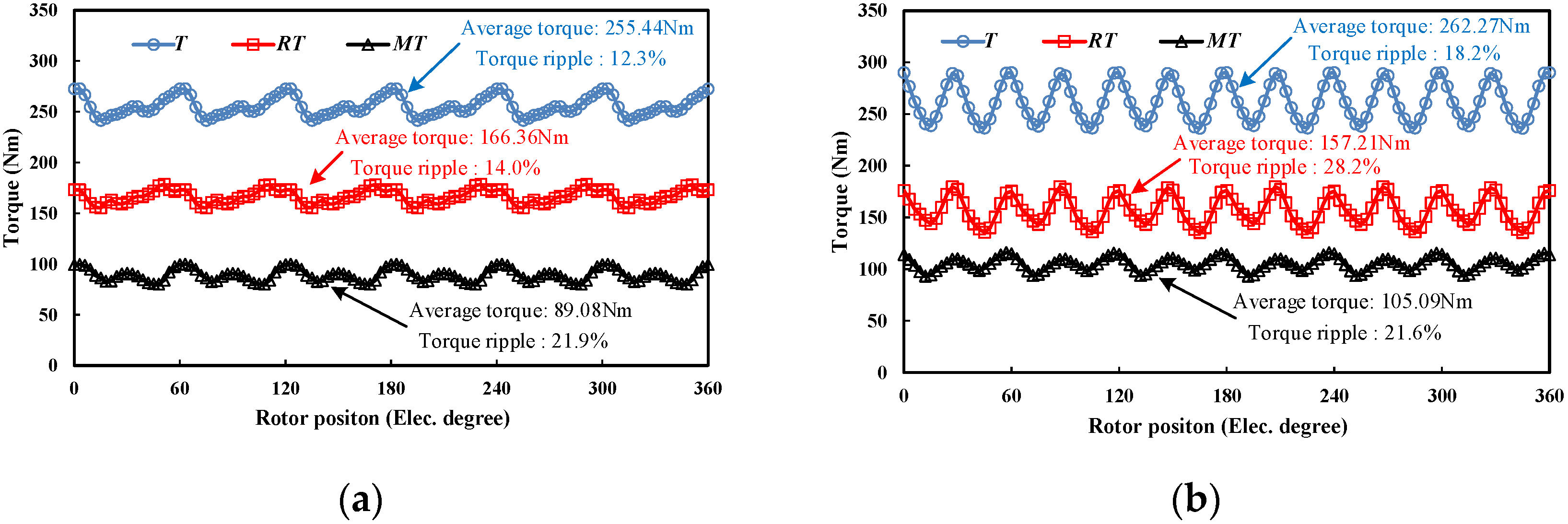
The on-load torque characteristics of the Prius 2010 and the MAS-IPM machines are shown in
Figure 9 and
Figure 10. The torque separation results obtained by the frozen permeability method [
10,
11] are shown in
Figure 9a,b, respectively. Due to the asymmetrical PM configuration,
γs of the proposed MAS-IPM machine is reduced by 15 electrical degrees compared to the Prius IPM machine.
4.3. Torque/Power vs. Speed Curves
The field-weakening capability is a key characteristic for the traction machines for electric vehicles. The torque/power-speed curves are shown in
Figure 11a,b, respectively. It demonstrates that the proposed machine can achieve higher torque and power capability over a whole speed range.
4.4. Iron Loss and Efficiency Maps
The loss in the machine mainly contains the iron and copper losses. The iron, hysteresis, eddy current, and copper losses can be calculated by
where
Pi,
Ph,
Pe, and
Pc are iron, hysteresis, eddy current, and copper losses, respectively;
Kh and
Ke are the coefficients of hysteresis and eddy current losses, respectively;
f is the operating frequency of the machine;
Bm is the flux density;
α,
γ, and
δ are the coefficients of the empiric formula;
Ra is the armature winding resistance; and
Ia is the phase current RMS value.
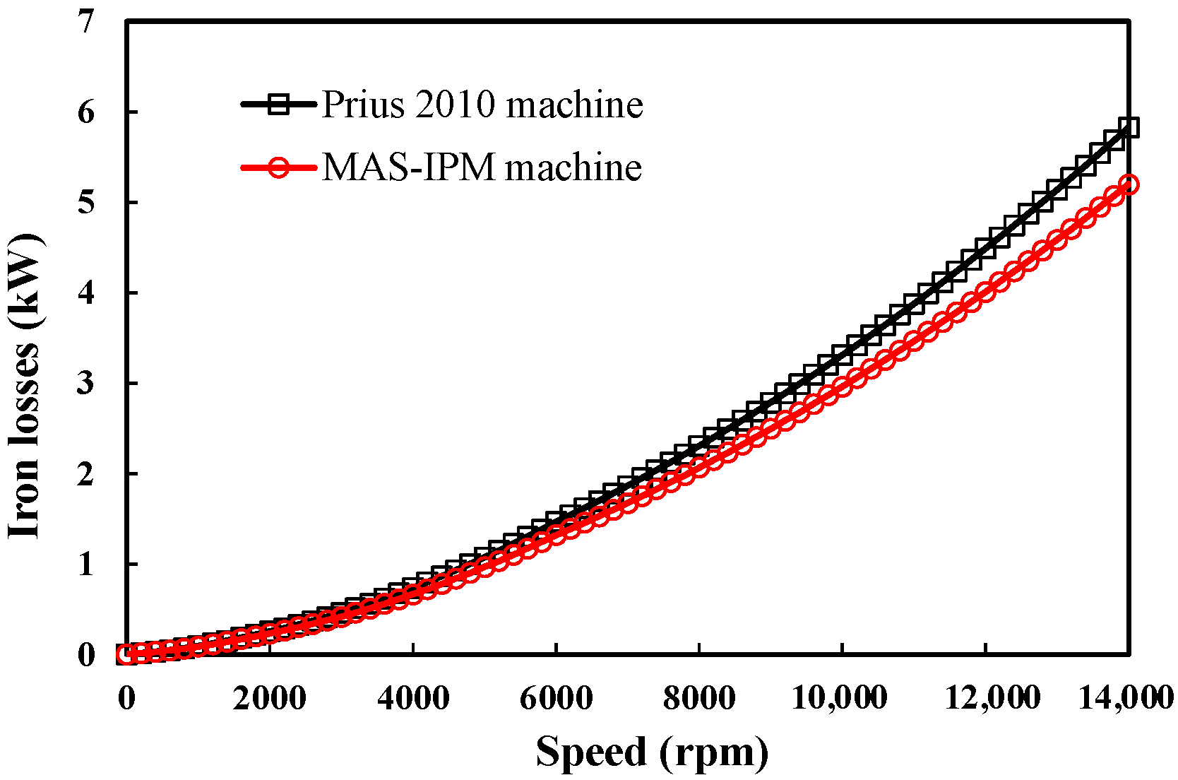
The iron losses of the two machines are given in
Figure 12. It can be observed that the two machines show similar iron losses when the speed is lower than 6000 rpm. Besides, due to lower THD of the back-EMF, the MAS-IPM machine shows lower iron loss under high speed range. The efficiency maps of the two machines are illustrated in
Figure 13. The maximum efficiency of the MAS-IPM machine is 0.7% higher than that of the Prius 2010. It can be seen that the high efficiency over a wider operating region can be achieved in the MAS-IPM machine due to its lower iron loss. The related electromagnetic performances of the two machines are given in
Table 3. As a whole, the MAS effect of the proposed asymmetrical PM configuration for the torque improvement is confirmed. Meanwhile, compared to the Prius IPM machine, the proposed machine exhibits higher RMS flux linkage, RMS back-EMF and lower cogging torque, as well as higher MT, RT utilization ratio, and operating efficiency.
5. Conclusions
A novel IPM machine with a MAS effect is proposed in this paper. Due to the asymmetrical PM configuration, the proposed machine benefits from the reduced γs, improving the MT and RT utilization ratios. Hence, the total torque can be further improved. Based on FEM, the design variables of the proposed MAS-IPM machine are optimized to maximize the torque capability by defining an asymmetry ratio. Afterwards, the electromagnetic characteristics of the proposed MAS-IPM machine are investigated and compared with those of the Prius 2010 machine. It can be found that the proposed machine shows higher RMS back-EMF, lower total harmonic distortions, and lower cogging torque. In addition, the MAS-IPM machine exhibits a higher peak torque, a higher high-speed power maintaining capability, as well as wider high efficiency operating regions. In summary, the results confirm the MAS effect of the proposed asymmetrical PM configuration due to its performance improvement. A prototype of the MAS-IPM machine will be manufactured and the test results will be reported in due course.
Author Contributions
Conceptualization, Y.G., H.Y. and W.W.; methodology, H.Y., Y.G. and W.W.; software, H.Y., Y.G. and W.W.; validation, H.Y., Y.G. and W.W.; formal analysis, H.Y., Y.G. and W.W.; investigation, Y.L.; resources, H.Y., Y.G. and W.W.; data curation, W.W.; writing—original draft preparation, H.Y., Y.G. and W.W.; writing—review and editing, H.Y., W.W., and H.L.; visualization, H.Y., H.L. and Y.L.; supervision, H.Y., Y.G. and W.W.; project administration, H.Y., and H.L.; funding acquisition, H.Y. and H.L. All authors have read and agreed to the published version of the manuscript.
Funding
This work was jointly supported in part by National Natural Science Foundations of China under Grants (52077033 and 52037002), in part by Key R&D Program of Jiangsu Province (BE2021052), in part by the Fundamental Research Funds for the Central Universities (2242017K41003), in part by Supported by the “Zhishan Youth Scholar” Program of Southeast University, in part the Jiangsu Provincial Key Laboratory of Smart Grid Technology and Equipment, Southeast University (7716008046), and in part by supported by “the Excellence Project Funds of Southeast University”.
Conflicts of Interest
The authors declare no conflict of interest.
References
- Yang, Y.; Castano, S.M.; Yang, R.; Kasprzak, M.; Bilgin, B.; Sathyan, A.; Dadkhah, H.; Emadi, A. Design and comparison of interior permanent magnet motor topologies for traction applications. IEEE Trans. Transp. Electrif. 2017, 3, 86–97. [Google Scholar] [CrossRef]
- Zhu, S.; Chen, W.; Xie, M.Q.; Liu, C.; Wang, K. Electromagnetic performance comparison of multi-layered interior permanent magnet machines for EV traction applications. IEEE Trans. Magn. 2018, 54, 1–5. [Google Scholar] [CrossRef]
- Huynh, T.A.; Hsieh, M.F. Comparative study of PM-assisted SynRM and IPMSM on constant power speed range for EV applications. IEEE Trans. Magn. 2017, 53, 1–6. [Google Scholar] [CrossRef]
- Zhao, W.; Chen, D.; Lipo, T.A.; Kwon, B.-I. Performance Improvement of ferrite-assisted synchronous reluctance machines using asymmetrical rotor configurations. IEEE Trans. Magn. 2015, 51, 1–4. [Google Scholar] [CrossRef]
- Zhao, W.; Xing, F.; Wang, X.; Lipo, T.A.; Kwon, B.I. Design and analysis of a novel PM-assisted synchronous reluctance machine with axially integrated magnets by the finite-element method. IEEE Trans. Magn. 2017, 53, 1–4. [Google Scholar] [CrossRef]
- Li, Y.; Bobba, D.; Sarlioglu, B. Design and optimization of a novel dual-rotor hybrid PM machine for traction application. IEEE Trans. Ind. Electron. 2018, 65, 1762–1771. [Google Scholar] [CrossRef]
- Yang, H.; Li, Y.; Lin, H.; Zhu, Z.Q.; Lyu, S.; Wang, H.; Fang, S.; Huang, Y. Novel reluctance axis shifted machines with hybrid rotors. In Proceedings of the IEEE Energy Conversion Congress and Exposition, Cincinnati, OH, USA, 1–5 October 2017; pp. 2362–2367. [Google Scholar] [CrossRef]
- Ocak, O.; Aydin, M. A new hybrid permanent magnet synchronous motor with two different rotor sections. IEEE Trans. Magn. 2017, 53, 1–5. [Google Scholar] [CrossRef]
- Xing, F.; Zhao, W.; Kwon, B.I. Design and optimisation of a novel asymmetric rotor structure for a PM-assisted synchronous reluctance machine. IET Electric Power Appl. 2019, 13, 573–580. [Google Scholar] [CrossRef]
- Zhao, W.; Lipo, T.A.; Kwon, B.-I. Optimal design of a novel asymmetrical rotor structure to obtain torque and efficiency improvement in surface inset PM motors. IEEE Trans. Magn. 2015, 51, 1–4. [Google Scholar] [CrossRef]
- Xu, G.; Liu, G.; Zhao, W.; Chen, Q.; Du, X. Principle of torque-angle approaching in a hybrid rotor permanent-magnet motor. IEEE Trans. Ind. Electron. 2019, 66, 2580–2591. [Google Scholar] [CrossRef]
| Publisher’s Note: MDPI stays neutral with regard to jurisdictional claims in published maps and institutional affiliations. |
© 2021 by the authors. Licensee MDPI, Basel, Switzerland. This article is an open access article distributed under the terms and conditions of the Creative Commons Attribution (CC BY) license (https://creativecommons.org/licenses/by/4.0/).


