
Impact of the Roller Press Briquetting Process on the Morphological and Mechanical Properties of Apatite Ore

 , , , , and
Abstract
1. Introduction
2. Materials and Methods
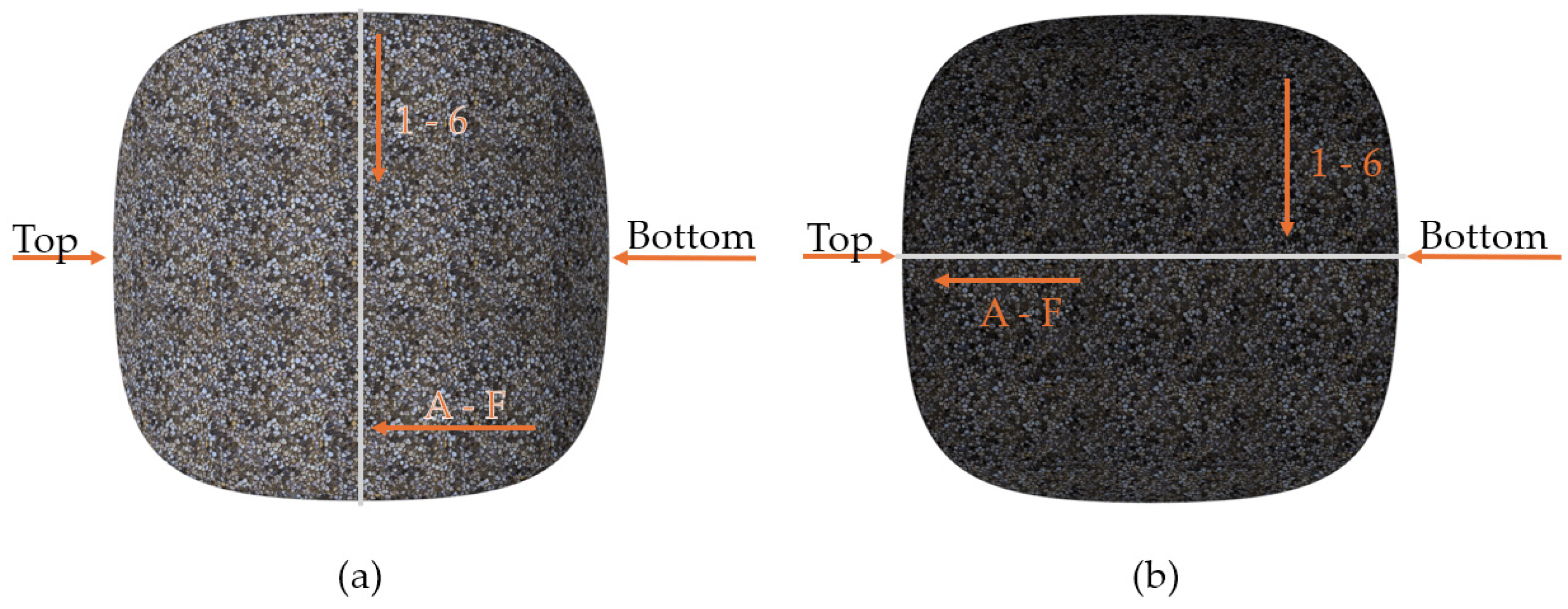
- On the front side, in fields A3, B3, C3, D3, E3, F3, with the measurement path parallel to the top-bottom line.
- Weighing of the dry briquette in the air;
- Weighing the briquette submerged in liquid (distilled water);
- Infusing the briquette with paraffin wax, and weighing it in the air after drying.
3. Results and Discussion
4. Conclusions
Author Contributions
Funding
Institutional Review Board Statement
Informed Consent Statement
Data Availability Statement
Acknowledgments
Conflicts of Interest
References
- Mao, M.; Rukhlov, A.S.; Rowins, S.M.; Spence, J.; Coogan, L.A. Apatite Trace Element Compositions: A Robust New Tool for Mineral Exploration*. Econ. Geol. 2016, 111, 1187–1222. [Google Scholar] [CrossRef]
- O’Sullivan, G.; Chew, D.; Kenny, G.; Henrichs, I.; Mulligan, D. The Trace Element Composition of Apatite and Its Application to Detrital Provenance Studies. Earth-Sci. Rev. 2020, 201, 103044. [Google Scholar] [CrossRef]
- Orabi, A.; El-Sheikh, E.; Hassanin, M.; El Kady, M.; Abdel-Khalek, M.; Mowafy, A. Extraction of Rare Earth Elements from Abu–Tartour Wet Process Phosphoric Acid Using Synthesized Salicylaldehyde Azine. Miner. Eng. 2018, 122, 113–121. [Google Scholar] [CrossRef]
- Ihlen, P.M.; Schiellerup, H.; Gautneb, H.; Skår, Ø. Characterization of Apatite Resources in Norway and Their REE Potential—A Review. Ore Geol. Rev. 2014, 58, 126–147. [Google Scholar] [CrossRef]
- Ramos, S.J.; Dinali, G.S.; de Carvalho, T.S.; Chaves, L.C.; Siqueira, J.O.; Guilherme, L.R.G. Rare Earth Elements in Raw Materials and Products of the Phosphate Fertilizer Industry in South America: Content, Signature, and Crystalline Phases. J. Geochem. Explor. 2016, 168, 177–186. [Google Scholar] [CrossRef]
- Yang, B.; Cao, S.; Zhu, Z.; Yin, W.; Sheng, Q.; Sun, H.; Yao, J.; Chen, K. Selective Flotation Separation of Apatite from Dolomite Utilizing a Novel Eco-Friendly and Efficient Depressant for Sustainable Manufacturing of Phosphate Fertilizer. J. Clean. Prod. 2021, 286, 124949. [Google Scholar] [CrossRef]
- Ryszko, U.; Rusek, P.; Kołodyńska, D. Quality of Phosphate Rocks from Various Deposits Used in Wet Phosphoric Acid and P-Fertilizer Production. Materials 2023, 16, 793. [Google Scholar] [CrossRef]
- Dahanayake, K.; Ratnayake, M.P.K.; Sunil, P.A. Potential of Eppawala Apatite as a Directly Applied Low-Cost Fertilizer for Rice Production in Sri Lanka. Fertil. Res. 1995, 41, 145–150. [Google Scholar] [CrossRef]
- Giyasidinov, A.L.; Sultonov, B.E.; Dormeshkin, O. Study on the Composition of Phosphorus Fertilizers Obtained on the Basis of Kizilkum Phosphorites and Nitric Acid. J. Chem. Technol. Metall. 2023, 58, 347–352. [Google Scholar] [CrossRef]
- Syvyi, M.; Demyanchuk, P.; Havryshok, B.; Zablotskyi, B. Phosphates of Ukraine as raw materials for the production of mineral fertilizers and ameliorants. Gospod. Surowcami Miner.—Miner. Resour. Manag. 2023, 35, 5–26. [Google Scholar] [CrossRef]
- Phosphate Fertilizer Market Size & Share Report, 2040. Available online: https://www.grandviewresearch.com/industry-analysis/phosphate-fertilizers-market (accessed on 29 August 2023).
- Cordell, D.; White, S. Life’s Bottleneck: Sustaining the World’s Phosphorus for a Food Secure Future. Annu. Rev. Environ. Resour. 2014, 39, 161–188. [Google Scholar] [CrossRef]
- Chen, M.; Li, Z.; Huang, P.; Li, X.; Qu, J.; Yuan, W.; Zhang, Q. Mechanochemical Transformation of Apatite to Phosphoric Slow-Release Fertilizer and Soluble Phosphate. Process Saf. Environ. Prot. 2018, 114, 91–96. [Google Scholar] [CrossRef]
- de Morais, E.G.; Silva, C.A. Novel Slow-Release NPK Biochar-Based Fertilizers with Acidulated Apatite: Evaluation of the Fertilization Value in a Short-Term Experiment. J. Soil Sci. Plant Nutr. 2023, 23, 4937–4954. [Google Scholar] [CrossRef]
- Timofeeva, T.A.; Chebotar, V.K.; Demidov, D.V.; Gaidukova, S.E.; Yakovleva, I.V.; Kamionskaya, A.M. Effects of Apatite Concentrate in Combination with Phosphate-Solubilizing Microorganisms on the Yield of Ryegrass Cultivar Izorskiy. Agronomy 2023, 13, 1568. [Google Scholar] [CrossRef]
- Aarnio, T.; Räty, M.; Martikainen, P.J. Long-Term Availability of Nutients in Forest Soil Derived from Fast- and Slow-Release Fertilizers. Plant Soil 2003, 252, 227–239. [Google Scholar] [CrossRef]
- Hackman, J.; Ozyhar, T.; Chien, S.H.; Hilty, F.; Woodley, A.; Cook, R.L. Evaluation of Synthetic Hydroxyapatite as a Potential Phosphorus Fertilizer for Application in Forest Plantations. For. Sci. Technol. 2022, 18, 127–134. [Google Scholar] [CrossRef]
- Tennakone, K.; Weerasooriya, S.V.R.; Jayatissa, D.L.; Damayanthi, M.L.W.D.; Silva, L.H.K. Non Hygroscopic Superphosphate Fertilizer from Apatite and Hydrochloric Acid. Fertil. Res. 1988, 16, 87–96. [Google Scholar] [CrossRef]
- Review of AHDB-Funded Research on Phosphorus Management in Arable Crops|AHDB. Available online: https://ahdb.org.uk/review-of-ahdb-funded-research-on-phosphorus-management-in-arable-crops (accessed on 18 September 2023).
- Conley, D.J.; Paerl, H.W.; Howarth, R.W.; Boesch, D.F.; Seitzinger, S.P.; Havens, K.E.; Lancelot, C.; Likens, G.E. Controlling Eutrophication: Nitrogen and Phosphorus. Science 2009, 323, 1014–1015. [Google Scholar] [CrossRef]
- Blackwell, M.S.A.; Darch, T.; Haslam, R.P. Phosphorus Use Efficiency and Fertilizers: Future Opportunities for Improvements. Front. Agric. Sci. Eng.—FASE 2019, 6, 332–340. [Google Scholar] [CrossRef]
- Smith, V.H. Eutrophication of Freshwater and Coastal Marine Ecosystems a Global Problem. Environ. Sci. Pollut. Res. 2003, 10, 126–139. [Google Scholar] [CrossRef]
- Altybaev, J.M. Scientific and Technological Bases of Obtaining Ni-Co Containing Agglomerates in Phosphorus Production. Ph.D. Thesis, M.O. Auezov South Kazakhstan State University, Shymkent, Kazakhstan, 2013. [Google Scholar]
- Mar, S.S.; Okazaki, M. Investigation of Cd Contents in Several Phosphate Rocks Used for the Production of Fertilizer. Microchem. J. 2012, 104, 17–21. [Google Scholar] [CrossRef]
- Iretskaya, S.N.; Chien, S.H.; Menon, R.G. Effect of Acidulation of High Cadmium Containing Phosphate Rocks on Cadmium Uptake by Upland Rice. Plant Soil 1998, 201, 183–188. [Google Scholar] [CrossRef]
- Zou, C.; Shi, Z.; Yang, Y.; Zhang, J.; Hou, Y.; Zhang, N. The Characteristics, Enrichment, and Migration Mechanism of Cadmium in Phosphate Rock and Phosphogypsum of the Qingping Phosphate Deposit, Southwest China. Minerals 2023, 13, 107. [Google Scholar] [CrossRef]
- Zalim, Y.; Benayada, A.; El Ahmadi, Z. Cadmium Removal from Cadmium-Containing Apatites by Ion-Exchange Reactions. ChemistrySelect 2022, 7, e202201862. [Google Scholar] [CrossRef]
- Santos, I.D.; Rodrigues, S.L.; Siqueira, J.O.; Monte, M.B.M.; Dutra, A.J.B. Effect of Partial Oxidation of Organic Matter on Cadmium Leaching from Phosphate. Miner. Eng. 2016, 99, 67–75. [Google Scholar] [CrossRef]
- Benredjem, Z.; Delimi, R.; Khelalfa, A. Phosphate Ore Washing by Na2 EDTA for Cadmium Removal: Optimization of the Operating Conditions. Pol. J. Chem. Technol. 2012, 14, 15–20. [Google Scholar] [CrossRef]
- Fan, Y.; Zhang, G.; Li, S.; Zhang, L.; Guo, J.; Feng, C. Mineral Liberation and Concentration Characteristics of Apatite Comminuted by High-Pressure GRU. Minerals 2024, 14, 1148. [Google Scholar] [CrossRef]
- Al-Wakeel, M.I. Effect of Mechanical Treatment on the Mineralogical Constituents of Abu-Tartour Phosphate Ore, Egypt. Int. J. Miner. Process. 2005, 75, 101–112. [Google Scholar] [CrossRef]
- Neradovsky, Y.N.; Kompanchenko, A.A.; Chernyavsky, A.V. Texture and Mineral Composition of Magmatic Apatite-Nepheline Ores: Technological Consequences (Exemplified by Khibiny). IOP Conf. Ser. Earth Environ. Sci. 2022, 988, 032031. [Google Scholar] [CrossRef]
- Best Available Techniques for Pollution Prevention and Control in the European Fertilizer Industry, Booklet No. 7 of 8: Production of NPK Compound Fertilizers by Nitrophosphate Route; Fertilizers Europe: Brussels, Belgium, 2000.
- Abouzeid, A.-Z.M. Physical and Thermal Treatment of Phosphate Ores—An Overview. Int. J. Miner. Process. 2008, 85, 59–84. [Google Scholar] [CrossRef]
- Zhantasov, K.T.; Bazhirova, K.N.; Toltebayeva, Z.D.; Zhantasova, D.M. Current Status, Problems and Prospects of Development of Phosphate Industry in Khazakhstan. Chem. Ind. Today 2013, 4–6. [Google Scholar]
- Kaliyan, N.; Morey, R.V. Natural Binders and Solid Bridge Type Binding Mechanisms in Briquettes and Pellets Made from Corn Stover and Switchgrass. Bioresour. Technol. 2010, 101, 1082–1090. [Google Scholar] [CrossRef]
- Tleuov, A.S. Waste Disposal of Enterprises of the Phosphorus Industry. Textbook; South Kazakhstan State University Named After M. Auezov: Shymkent, Kazakhstan, 2015. [Google Scholar]
- Magdziarz, A.; Kuźnia, M.; Bembenek, M.; Gara, P.; Hryniewicz, M. Briquetting of EAF Dust for Its Utilisation in Metallurgical Processes. Chem. Process Eng. 2015, 36, 263–271. [Google Scholar] [CrossRef]
- Zhang, H.; Hui, L.; Dong, J.; Xiong, H. Optimization of the Stainless Steel Dust Briquette Reduction Process for Iron, Chromium, and Nickel Recovery. High Temp. Mater. Process. 2018, 37, 785–791. [Google Scholar] [CrossRef]
- Grover, P.D.; Mishra, S.K. Biomass Briquetting: Technology and Practices; Food and Agriculture Organization of the United Nations: Bangkok, Thailand, 1996. [Google Scholar]
- Bembenek, M.; Dzik, T.; Smyła, J.; Kozłowski, A.; Wojtas, P. Comparative Analysis of Combustion of Qualified Composite Fuel for the Transitional Period in the Household and Communal Sector in Poland. Manag. Syst. Prod. Eng. 2022, 30, 362–369. [Google Scholar]
- Kaur, A.; Roy, M.; Kundu, K. Densification of Biomass by Briquetting: A Review. Int. J. Recent Sci. Res. 2017, 8, 20561–20568. [Google Scholar] [CrossRef]
- Mitchual, S.J.; Katamani, P.; Afrifa, K.A. Fuel Characteristics of Binder Free Briquettes Made at Room Temperature from Blends of Oil Palm Mesocarp Fibre and Ceiba Pentandra. Biomass Convers. Biorefinery 2019, 9, 541–551. [Google Scholar] [CrossRef]
- Obi, O.F.; Pecenka, R.; Clifford, M.J. A Review of Biomass Briquette Binders and Quality Parameters. Energies 2022, 15, 2426. [Google Scholar] [CrossRef]
- Xu, B.; Chu, M.; Hong, A.B.; Zhang, F.L. Comparative Study on Pyrolysis Characteristics of Lignite Binderless Briquette and Raw Coal. Appl. Mech. Mater. 2013, 318, 303–307. [Google Scholar] [CrossRef]
- Olugbade, T.; Ojo, O.; Mohammed, T. Influence of Binders on Combustion Properties of Biomass Briquettes: A Recent Review. BioEnergy Res. 2019, 12, 241–259. [Google Scholar] [CrossRef]
- Borowski, G. Wykorzystanie Brykietowania Do Zagospodarowania Odpadów; Lubelskie Towarzystwo Naukowe: Lublin, Poland, 2011; ISBN 978-83-62025-17-6. [Google Scholar]
- Michrafy, A.; Zavaliangos, A.; Cunningham, J.C. 4—Dry Granulation Process Modeling. In Predictive Modeling of Pharmaceutical Unit Operations; Pandey, P., Bharadwaj, R., Eds.; Woodhead Publishing: Sawston, UK, 2017; pp. 71–97. ISBN 978-0-08-100154-7. [Google Scholar]
- Bembenek, M. Badania i Perspektywy Nowych Obszarów Stosowania Pras Walcowych. Przem. Chem. 2017, 1, 39–41. [Google Scholar] [CrossRef]
- Bembenek, M.; Uhryński, A. Analysis of the Temperature Distribution on the Surface of Saddle-Shaped Briquettes Consolidated in the Roller Press. Materials 2021, 14, 1770. [Google Scholar] [CrossRef] [PubMed]
- ASTM E140-12B(2019)e1; Hardness Conversion Tables for Metals Relationship Among Brinell Hardness, Vickers Hardness, Rockwell Hardness, Superficial Hardness, Knoop Hardness, Scleroscope Hardness, and Leeb Hardness. ASTM International: West Conshohocken, PA, USA, 2019.
- Bembenek, M.; Krawczyk, J.; Frocisz, Ł.; Śleboda, T. The Analysis of the Morphology of the Saddle-Shaped Bronze Chips Briquettes Produced in the Roller Press. Materials 2021, 14, 1455. [Google Scholar] [CrossRef] [PubMed]
- Bembenek, M.; Buczak, M.; Baiul, K. Modelling of the Fine-Grained Materials Briquetting Process in a Roller Press with the Discrete Element Method. Materials 2022, 15, 4901. [Google Scholar] [CrossRef] [PubMed]
- Zięba, A. Influence of the Type of Briquetting Material on the Morphology of the Saddle-Shaped Briquette. Master’s Thesis, AGH Uniwersity of Krakow, Krakow, Poland, 2019. [Google Scholar]


| Element Symbol | Weight % | ||
|---|---|---|---|
| (a) 1 | (b) 1 | (c) 1 | |
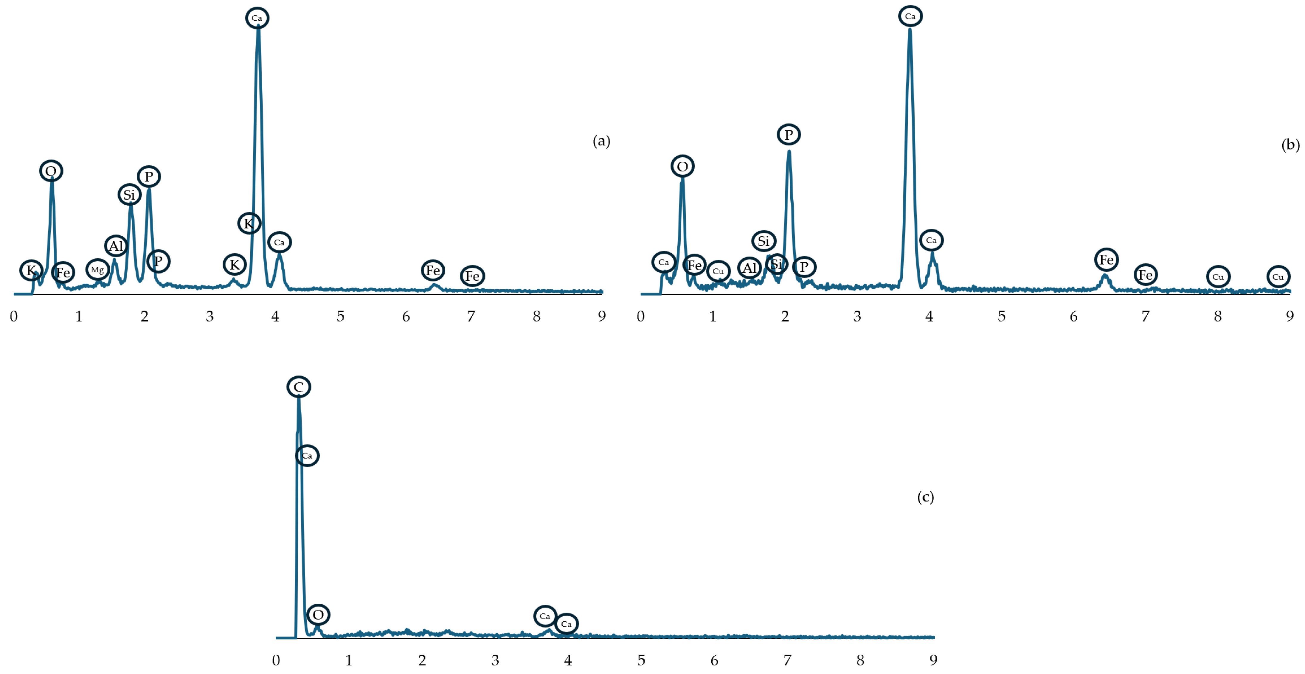
| O | 54.3 | 55.7 | 45.1 |
| Ca | 27.0 | 26.6 | 4.1 |
| P | 8.4 | 11.4 | - |
| Si | 5.4 | 2.0 | - |
| Al | 2.3 | 0.2 | - |
| Fe | 1.4 | 3.8 | - |
| K | 0.8 | - | - |
| Mg | 0.4 | - | - |
| Cu | - | 0.3 | - |
| C | - | - | 50.8 |
| 1 | 2 | 3 | 4 | 5 | 6 | ||
|---|---|---|---|---|---|---|---|
| Bottom | A | x | x | x | x | x | x |
| B | x | 38 | 40 | 42 | 27 | x | |
| C | 25 | 40 | 61 | 51 | 32 | 27 | |
| D | 32 | 35 | 53 | 59 | 53 | 35 | |
| E | x | 33 | 39 | 31 | 30 | x | |
| Top | F | x | x | x | x | x | x |
| 1 | 2 | 3 | 4 | 5 | 6 | ||
|---|---|---|---|---|---|---|---|
| Bottom | A | x | x | x | x | x | x |
| B | x | x | 40 | 39 | 28 | x | |
| C | x | 28 | 32 | 32 | 27 | x | |
| D | x | 26 | 30 | 31 | x | x | |
| E | x | x | 28 | 25 | x | x | |
| Top | F | x | x | 27 | 26 | x | x |
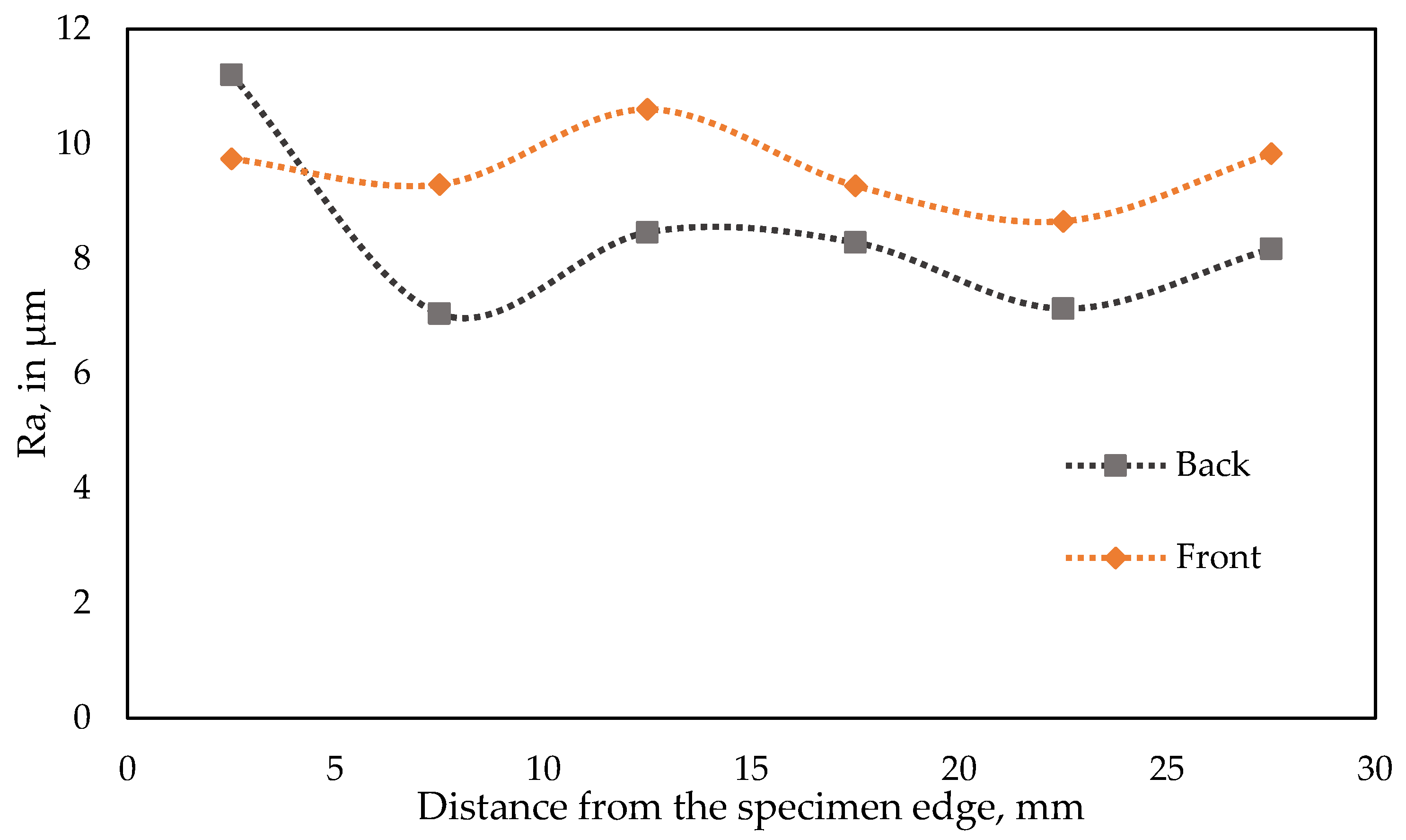
| Field Symbol | D1 | D2 | D3 | D4 | D5 | D6 |
|---|---|---|---|---|---|---|
| Ra, in µm | 11.20 | 7.04 | 8.46 | 8.28 | 7.13 | 8.17 |
| Rq, in µm | 15.33 | 8.88 | 10.87 | 10.41 | 9.38 | 10.39 |
| Rt, in µm | 136.77 | 115.18 | 117.21 | 121.53 | 143.81 | 130.84 |
| Field Symbol | A3 | B3 | C3 | D3 | E3 | F3 |
|---|---|---|---|---|---|---|
| Ra, in µm | 9.74 | 9.29 | 10.60 | 9.27 | 8.65 | 9.83 |
| Rq, in µm | 12.27 | 11.15 | 12.86 | 11.37 | 11.05 | 12.74 |
| Rt, in µm | 164.46 | 86.62 | 141.08 | 100.04 | 147.46 | 126.20 |
| Weight of the dry briquette, in g | 20.1265 |
| Weight of paraffin infused briquette, in g | 20.7392 |
| Weight of the briquette in distilled water, in g | 12.7583 |
| Bulk density, in g/cm3 | 2.51 |
| Porosity, in % | 21 |
Disclaimer/Publisher’s Note: The statements, opinions and data contained in all publications are solely those of the individual author(s) and contributor(s) and not of MDPI and/or the editor(s). MDPI and/or the editor(s) disclaim responsibility for any injury to people or property resulting from any ideas, methods, instructions or products referred to in the content. |
© 2025 by the authors. Licensee MDPI, Basel, Switzerland. This article is an open access article distributed under the terms and conditions of the Creative Commons Attribution (CC BY) license (https://creativecommons.org/licenses/by/4.0/).
Share and Cite
Bembenek, M.; Dmytriv, V.; Kowalski, Ł.; Turniak, K.; Frocisz, Ł.; Niyazbekova, R.; Krawczyk, J. Impact of the Roller Press Briquetting Process on the Morphological and Mechanical Properties of Apatite Ore. Materials 2025, 18, 1442. https://doi.org/10.3390/ma18071442
Bembenek M, Dmytriv V, Kowalski Ł, Turniak K, Frocisz Ł, Niyazbekova R, Krawczyk J. Impact of the Roller Press Briquetting Process on the Morphological and Mechanical Properties of Apatite Ore. Materials. 2025; 18(7):1442. https://doi.org/10.3390/ma18071442
Chicago/Turabian StyleBembenek, Michał, Vasyl Dmytriv, Łukasz Kowalski, Krzysztof Turniak, Łukasz Frocisz, Rimma Niyazbekova, and Janusz Krawczyk. 2025. "Impact of the Roller Press Briquetting Process on the Morphological and Mechanical Properties of Apatite Ore" Materials 18, no. 7: 1442. https://doi.org/10.3390/ma18071442
APA StyleBembenek, M., Dmytriv, V., Kowalski, Ł., Turniak, K., Frocisz, Ł., Niyazbekova, R., & Krawczyk, J. (2025). Impact of the Roller Press Briquetting Process on the Morphological and Mechanical Properties of Apatite Ore. Materials, 18(7), 1442. https://doi.org/10.3390/ma18071442