Abstract
With the expansion of photovoltaic (PV) systems, failures of bypass diodes (BPDs) embedded in PV modules can degrade the power-generation performance and pose safety risks. When a BPD fails, current circulates within the module, leading to overheating and eventual burnout of the failed BPD. The heating characteristics of a BPD depend on its fault resistance, and although many modules are connected in series in actual PV systems, the heating risk at the module-string level has not been sufficiently evaluated to date. In this study, a numerical simulation model is constructed to reproduce the operation of PV modules and module strings containing failed BPDs, and its validity is verified through experiments. The validated numerical simulation results quantitatively illustrate how series-connected PV modules modify the fault-resistance dependence of BPD heating under maximum power-point operation. The results show that, under maximum power-point operation, the fault resistance at which BPD heating becomes critical shifts depending on the number of series-connected modules examined, while the magnitude of the maximum heating decreases as the string length increases. The heat generated in a BPD at the maximum power point decreases as the number of series-connected modules increases for the representative string configurations analyzed. However, under open-circuit conditions due to power-conditioner abnormalities, the power dissipated in the failed BPD increases significantly, posing a very high risk of burnout. Considering that lightning strikes are one of the major causes of BPD failure, adopting diodes with higher voltage and current ratings and improving the thermal design of junction boxes are effective measures to reduce BPD failures. The simulation model constructed in this study, which was experimentally validated for short PV strings, can reproduce the electrical characteristics and heating behaviors of PV modules and strings with BPD failures with accuracy sufficient for comparative and parametric trend analysis, and serves as a practical tool for system-level safety assessment, design considerations, and maintenance planning within the representative configurations analyzed.
1. Introduction
The rapid expansion of renewable-energy deployment in recent years has resulted in a substantial global increase in the installation volume of photovoltaic (PV) modules, a trend that is expected to intensify in parallel with ongoing decarbonization and energy-transition initiatives [1,2,3,4]. Because PV modules are designed for prolonged outdoor operation, they are inevitably subjected to various environmental stressors—including temperature cycling, humidity, ultraviolet irradiation, wind loading, and precipitation—that induce gradual deterioration and, in some cases, functional failure [5,6,7]. Such failures not only impair power-generation performance and lead to considerable economic losses but may also precipitate severe safety hazards, including fires arising from localized heating or arcing phenomena, as well as electric-shock accidents during both operation and maintenance activities [8,9,10,11,12]. Accordingly, elucidating the underlying failure mechanisms of PV modules, establishing diagnostic methodologies capable of detecting early-stage degradation, and developing maintenance and asset-management strategies that explicitly incorporate safety considerations are essential for ensuring the long-term reliability of PV systems.
Bypass diodes (BPDs), which are integrated into PV modules to mitigate hotspots caused by partial shading or intrinsic cell-level defects, constitute critical protective components for stable module operation. Nevertheless, BPDs themselves are susceptible to failure as a result of prolonged aging or exposure to severe electrical and thermal stresses. In the event of a BPD failure, the module current circulates within a closed loop comprising the failed diode and the associated cell string, potentially inducing substantial thermal stress that may ultimately lead to diode overheating or catastrophic burnout. Such failures not only exacerbate performance degradation but also elevate the likelihood of hazardous events, including electric-shock risks and module-level fire incidents. Previous investigations demonstrated that the electrical characteristics of failed BPDs exhibit considerable variation, ranging from low-resistance short-circuit behavior to near open-circuit conditions [13]. Moreover, the observable failure states were similarly diverse: whereas some BPDs underwent pronounced thermal runaway culminating in burnout, others exhibited only modest temperature increases without any discernible external damage. These observations indicated that the thermal behavior of failed BPDs is governed primarily by the magnitude of the fault resistance. Subsequent analyses enabled us to clarify the quantitative relationship between fault resistance and BPD heating behavior under module-level operating conditions [14].
It is important to note, however, that these earlier findings were derived exclusively from controlled experiments focusing on an isolated PV module. In practical PV systems, multiple modules—often a dozen or more—are interconnected in series to form strings, resulting in a markedly different electrical environment in which fault currents, power dissipation, and thermal evolution may deviate significantly from single-module behavior. Consequently, the risk of BPD burnout within realistic PV strings has not been sufficiently characterized, leaving a critical gap in system-level safety assessment.
Therefore, the present study examines representative PV module string configurations to illustrate how string length influences power dissipation in failed bypass diodes. Unlike previous studies that primarily focused on hotspot formation or bypass-diode behavior at the single-module level, the novelty of this work lies in the extension of the analysis to series-connected PV module strings under realistic operating conditions. Using experimentally validated numerical modeling, this study investigates the influence of series-connected module number through representative short and long string configurations. Furthermore, the proposed framework enables direct comparison between maximum power point operation and load-release conditions, providing practical insights into fire and safety risks during both normal operation and maintenance, which have not been sufficiently addressed in prior studies. This analysis integrates experimental investigations with detailed numerical simulations conducted using MATLAB/Simulink R2024b, thereby enabling a focused quantitative assessment of the thermal and electrical behavior of failed bypass diodes under conditions representative of actual PV-system operation. In this context, the objective of the present study is not to introduce new physical device mechanisms, but to identify and quantitatively evaluate dominant system-level electrical factors governing thermal loading in failed bypass diodes. Specifically, this study focuses on (i) the coupling between fault resistance and maximum power-point operation, (ii) the voltage-dominant scaling effect introduced by series-connected PV modules, and (iii) the resulting shift and attenuation of peak power dissipation with increasing string length in the representative configurations considered.
2. Experimental and Simulation
2.1. Experiments on PV Strings Containing Failed BPDs
Figure 1 provides an overview of the experimental setup used to evaluate BPD failure within a PV module. In this experiment, a string configuration was adopted in which three PV modules, each equipped with three cell strings and BPDs, were connected in series, to reproduce a case where one BPD fails and to evaluate the heating behavior of the failed BPD. As shown in Figure 1, Units 1–3 represent the three cell strings within a single PV module, where Unit 1 corresponds to the cell string containing the failed bypass diode, and Units 2 and 3 correspond to healthy cell strings. Units 4 and 5 represent two additional healthy PV modules connected in series with the faulty module.
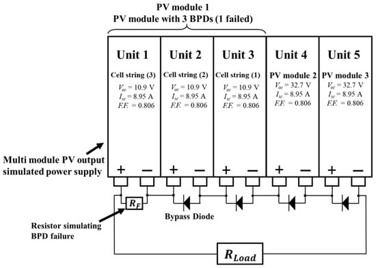
Figure 1.
Overview of experiments evaluating the output characteristics of PV module strings containing modules with BPD failures.
The output of the PV module is simulated using a multimodule power supply (Kernel System Co., Ltd., Osaka, Japan, MEP12281) capable of reproducing the electrical characteristics of PV modules. The output conditions per cell string are set as follows: open-circuit voltage Voc = 10.9 V, short-circuit current Isc = 8.95 A, and fill factor F.F. = 0.806. For PV modules in which all BPDs operate normally, the outputs of the three cell strings can be reproduced using a single simulated power supply. Therefore, the open-circuit voltage of each healthy PV module (Units 4 and 5) is set to 32.7 V, which corresponds to the sum of the open-circuit voltages of three series-connected cell strings.
Three simulated power supplies (Units 1–3) are used to reproduce a PV module with a failed BPD. In addition to Units 2 and 3, Units 4 and 5 simulate normal PV modules, each internally equipped with Schottky barrier diodes (SBDs; FSQ30A045, Kyocera Corporation, Kyoto, Japan, repetitive peak reverse voltage 45 V, average rectified current 30 A) functioning as bypass diodes. To reproduce BPD failure, Unit 1 is connected to either an electronic load (RIGOL, DL3031A, RIGOL Technologies, Beijing, China) or a variable resistor (RSSD 25X158, 1 Ω) instead of a bypass diode, thereby simulating failure conditions with various resistance values RF.
In this way, a PV module comprising three series-connected cell strings is reproduced, in which one bypass diode is intentionally failed. An electronic load RLoad (RIGOL, DL3031, RIGOL Technologies, Beijing, China) is connected to the output terminal of the PV module string that includes the failed BPD, and the current–voltage (I–V) characteristics are measured while sweeping in a constant-current mode. Based on this, the output characteristics of the PV module with simulated BPD failure are evaluated when the resistance value RF is varied. The terminal voltage and current of the resistor RF simulating the failed BPD are measured simultaneously. The heating behavior of the failed BPD is examined based on the power loss in RF.
2.2. Numerical Simulation Model of PV String with Failed BPD
Figure 2 shows a numerical simulation model of a solar cell. Figure 2a presents a MATLAB/Simulink model used to reproduce the electrical characteristics of a diode, based on the diode-current characteristics described in Equation (1). Figure 2b presents a numerical model representing the avalanche characteristics of a diode, modeled based on Equation (2) [15,16].
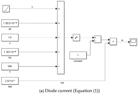
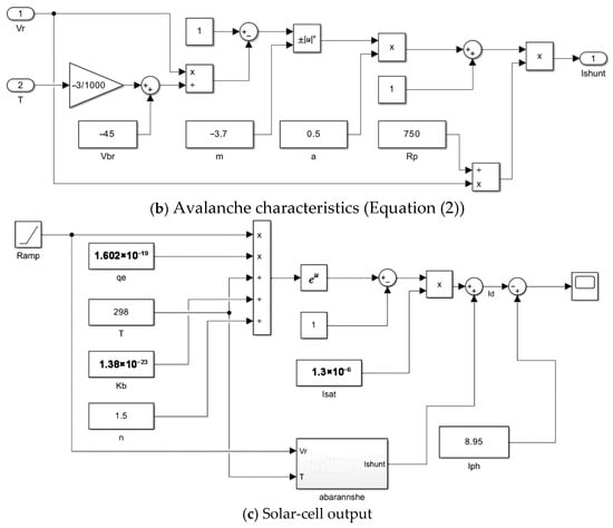
Figure 2.
Integrated simulation models of diode and solar-cell behavior: (a) diode current, (b) avalanche characteristics, and (c) solar-cell output.
The parameter conditions used in the simulation are as follows. The reverse saturation current Isat = 3.8 × 10⁻⁷ A, breakdown voltage Vr = −100 V, operating temperature T = 293 K, parallel resistance Rp = 750 Ω, ideality factor n = 1.5, constant a = 0.1, and constant m = −3.7. The electron charge qe and Boltzmann constant kb were set to their standard values. These values are conditions for reproducing output characteristics equivalent to those of the PV module used in the actual experiment.
Figure 2c presents a numerical simulation model for reproducing the output characteristics of a solar cell. This model is constructed incorporating the photocurrent Iph in the diode-characteristic models given by Equations (1) and (2) and presented in Figure 2a,b. This reproduces the conditions of the actual experiment described in Section 2.1 and simulates a configuration in which three cell strings are connected in series, each consisting of 18 series-connected solar cells (a total of 54 cells). Therefore, in the simulation, the Voc per cell is set to 0.606 V, Isc to 8.95 A, and F.F. to 0.806.
The models shown in Figure 3 do not introduce additional physical formulations; rather, they represent the direct graphical implementation of the diode and solar-cell equations defined in Equations (1) and (2) within the Simulink environment. Figure 3a presents a model of a cell string with an operational BPD. In this model, the voltage value per cell obtained from the cell model in Figure 2 is multiplied by 18 to reproduce a cell string consisting of 18 cells connected in series. Furthermore, by connecting a BPD in parallel to the string, the output voltage–current characteristics of a healthy cell string (cluster) are simulated.
Figure 3.
Graphical implementation of the electrical models defined by Equations (1) and (2) in the Simulink environment: (a) normal cell string with a normal bypass diode, (b) cell string with a failed bypass diode, (c) three-cluster PV module containing one faulty cluster, and (d) PV module string composed of one faulty module and two normal modules.
Figure 3b is a model of a cell string with a failed BPD. When a BPD fails in a short-circuit–like manner, it behaves as a resistive element under a forward voltage VF or in the reverse-bias voltage region [12]. Therefore, in this study, the short-circuit failure of a BPD is reproduced by adding a resistor RF in parallel to the diode model shown in Figure 2c.
Figure 3c presents a model of a PV module equipped with three cell strings and BPDs. This model represents a PV module with three series-connected cell strings by combining the three cell-string models constructed in Figure 2c (Voc = 10.9 V, Isc = 8.95 A) in series.
Figure 3d presents a model of a PV module string in which three PV modules, each equipped with three cell strings and BPDs, are connected in series. In this simulation, a condition is simulated wherein one BPD fails in one of the three PV modules connected in series, to reproduce the output characteristics under BPD failure.
Using the above configurations, the output characteristics are analyzed under the case when one BPD fails in a module string consisting of three PV modules connected in series, each with three cell strings and BPDs. Simultaneously, the power consumption at the site corresponding to the failed BPD is calculated, and the heating risk in the failed BPD is examined.
Due to experimental constraints, validation of the numerical model was limited to PV strings consisting of up to three series-connected modules. The agreement between experimental and simulation results for one-module and three-module configurations establishes the validity of the model within the experimentally accessible range. The same experimentally validated model is subsequently applied to investigate longer PV strings (e.g., 18 modules) through numerical simulation.
3. Simulation and Experimental Results
3.1. I–V and Power–Voltage (P–V) Characteristics of PV Module with Failed BPD and PV Module String
Figure 4 presents the I–V and P–V characteristics of a PV module containing a failed BPD, represented by introducing a resistance RF. The figure compares the experimentally measured results with the corresponding numerical simulation results. As shown in Figure 4, decreasing the fault resistance RF of the BPD leads to reductions in both the open-circuit voltage and the operating voltage. This voltage drop is caused by the decrease in the operating voltage of the cell string (Unit 3) that includes RF.
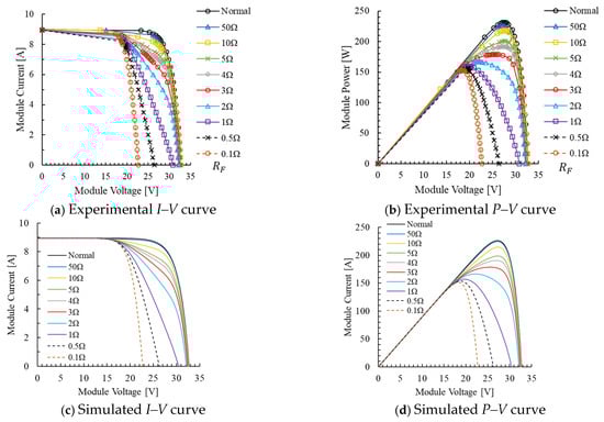
Figure 4.
I–V and P–V characteristics of a single PV module with one failed BPD of resistance RF.
Figure 5 presents the I–V and P–V characteristics of a PV module string in which three PV modules are connected in series. It consists of one PV module with a failed BPD of resistance RF and two healthy PV modules. The failed BPD module has three cell strings and BPDs, and reproduces the condition in which one of the BPDs fails. As in the single-module case shown in Figure 4, the operating voltage of the cell string including RF decreases, resulting in a reduction in both the open-circuit voltage and the operating voltage of the entire string. The amount of voltage variation in the string corresponds to the voltage drop of the cell string that includes the failed BPD.
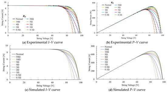
Figure 5.
I–V and P–V characteristics of a PV module with three cell strings and three BPDs, one of which is a failed BPD of resistance RF, within a three-module series string.
The experimental results of the BPD failure simulation, presented in Figure 4 and Figure 5, are in good agreement with the simulation results. This confirms that the constructed numerical simulation model appropriately reproduces the output characteristics of the PV module and module string with a failed BPD. The purpose of the simulation model is to capture the dominant trends and relative changes in power dissipation caused by bypass-diode failure rather than exact numerical matching. The close agreement observed in the operating points and maximum power values across experiments and simulations confirms that the model is suitable for comparative and parametric analyses.
3.2. Relationship Between BPD Fault Resistance and Power Consumption
Figure 6 shows the power dissipated in the failed BPD when the PV module and PV module string with a failed BPD operate at various resistance values RF. As PV power-generation systems are operated under maximum power-point tracking (MPPT) control by the power conditioner, they normally operate at the maximum power point during power generation. Therefore, the heating behavior of a failed BPD in an operating PV power-generation system can be evaluated based on the power dissipated in the failed BPD (RF) under maximum power-point operation. In this study, the heating risk is estimated from the power dissipated in the failed BPD (RF) when the PV module and module string are operated at the maximum power point.
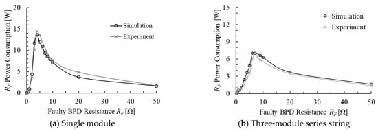
Figure 6.
Relationship between the power dissipated in the failed BPD (RF) and its fault resistance RF in a PV module and PV module strings operating at the maximum power point.
Figure 6 indicates that, when a PV module with a failed BPD is operated at the maximum power point, the power dissipated in the failed BPD exhibits a pronounced maximum at an intermediate fault-resistance value. For the representative cases examined here, this maximum appears at different resistance values depending on the number of series-connected modules.
In the simulation results, the power was 13.6 W at RF = 4 Ω for a single PV module, and 7.0 W at RF = 7 Ω for a three-module series string. Considering that the contact and wire resistances are included in the experiment, and that the measurement interval of the I–V characteristics is different for the experiment (0.1 A per sampling) and simulation (0.005 A per sampling), the RF values obtained from the experiment and simulation, at the maximum power point, are in good agreement; the power dissipated is also consistent. These results imply that the constructed model is valid.
The above results show that when the PV power-generation system operates at the maximum power point, if the BPD fails at a specific resistance value, the power dissipated in the failed BPD, which is the heat generated, becomes large. It is also confirmed that the fault resistance value showing maximum power dissipated varies depending on the number of PV modules connected in series. Furthermore, it is shown that the constructed simulation model can reproduce the output characteristics of a PV module string in which a BPD failure has occurred. The agreement between experimental results and numerical simulations for the single-module and three-module configurations confirms the validity of the proposed model within the experimentally accessible range.
Based on this validated model, numerical simulations were conducted to illustrate how power dissipation in a failed BPD changes between representative short and long PV module strings.
As the number of series-connected modules increases, the string voltage at the maximum power point increases, whereas the string current exhibits only a moderate change. As a result, the fault resistance corresponding to the maximum power dissipation shifts toward higher resistance values, while the absolute magnitude of the dissipated power decreases. This trend is consistent with the behavior observed experimentally and numerically for the single-module and three-module cases shown in Figure 6, confirming that the simulation model captures the dominant dependence on string length.
3.3. Illustration of BPD Power Dissipation Behavior in a Long PV Module String
To illustrate how the power dissipation behavior of a failed BPD changes in a representative long PV module string, additional numerical simulations were conducted by extending the validated model to longer module strings. Figure 7 shows the relationship between the fault resistance RF and the power dissipated in a failed BPD for a string consisting of 18 series-connected PV modules, operating under maximum power-point conditions. The results show that, for an 18-module series string, the power dissipated in the failed BPD reaches a maximum at an intermediate fault-resistance range. In this representative 18-module configuration, the peak appears at a higher resistance compared with shorter strings, while the magnitude of the peak power is reduced. Compared with the single-module and three-module cases shown in Figure 6, the peak power dissipation decreases as the number of series-connected modules increases, while the fault resistance corresponding to the maximum power shifts toward higher resistance values.
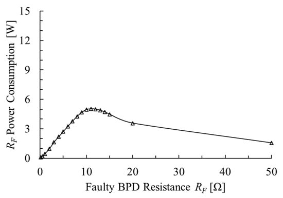
Figure 7.
Relationship between the power dissipated in the failed BPD (RF) and its fault resistance RF in a PV module string of 18 series-connected modules containing one module with a failed BPD, operating at the maximum power point (simulation).
4. Discussion
This study provides quantitative interpretation of thermal loading in failed bypass diodes. Rather than proposing new device-level physical mechanisms, the contribution of this work lies in isolating and quantifying how electrical operating conditions and string configuration govern power dissipation in failed BPDs, noting that such dependencies cannot be inferred from single-module analysis alone.
The results presented in this study are based on a specific PV module rating; however, similar qualitative trends may be expected for modules with different power ratings and cell configurations. For higher-power modules, increased short-circuit current and maximum power-point voltage may shift the fault resistance corresponding to maximum power dissipation and increase the absolute magnitude of thermal loading in a failed BPD. Conversely, lower-power modules would be expected to exhibit reduced power dissipation levels. Since the proposed simulation model explicitly incorporates module electrical parameters, it can be readily adapted to evaluate BPD heating behavior for PV modules with different power ratings.
The results for single-module and multi-module strings indicate that the fault resistance corresponding to maximum power dissipation shifts as additional modules are connected in series. This behavior reflects the voltage-dominant scaling of the PV string under maximum power-point operation, whereby the increase in operating voltage with string length exceeds the corresponding change in current. As a result, the peak power dissipation occurs at higher fault resistance values, while its absolute magnitude decreases as the number of series-connected modules increases.
Taken together, the results for one-module and three-module strings, combined with the extrapolated simulation for an eighteen-module string, illustrate a consistent tendency in how power dissipation in a failed BPD changes with PV string length. As the number of modules increases, the operating voltage of the string rises more than the current, shifting the peak power dissipation to higher RF values while decreasing its magnitude. While the present study does not exhaustively sweep all module parameters and environmental conditions, it establishes a baseline dependency of power dissipation on string length and fault resistance that is prerequisite for more focused multi-parameter studies. The framework presented here is therefore intended as a foundation for extended analyses rather than a complete parametric exploration. In this study, three-module strings were selected for experimental validation because they represent the longest configuration that could be reliably realized within the constraints of the laboratory setup, while still capturing essential string-level electrical interactions. The eighteen-module string was chosen as a representative longer-string scenario to illustrate how the identified trends extend to practical PV system scales commonly used in field installations. The present analysis does not constitute a systematic numerical sweep over all possible string lengths, module types, or environmental conditions; rather, it is intended to demonstrate representative system-level dependencies of BPD heating on string length and fault resistance.
As demonstrated by the simulation results in Section 3.3 (Figure 7), the power dissipated in a failed BPD in a long PV-module string exhibits a clear dependence on the fault resistance and the number of series-connected modules. These findings are directly derived from the validated numerical model, whose accuracy was experimentally confirmed for single-module and three-module configurations, thereby justifying its application to longer module strings. Based on the simulation results shown in Figure 6 and Figure 7, the heating of a failed BPD during maximum power-point operation clearly decreases as the number of series-connected modules increases. Taken together, these results show that, under the conditions examined, the thermal loading in a failed BPD can reach comparatively high levels over a broad intermediate range of fault resistance during maximum power-point operation. In practical PV systems, the thermal load on a failed BPD may be further influenced by the dynamic behavior of the MPPT algorithm. Unstable or slow MPPT control can cause prolonged operation away from the steady-state maximum power point, potentially resulting in higher or fluctuating power dissipation in the failed BPD. Such transient conditions may increase thermal stress compared with the steady-state MPPT operation considered in this study, suggesting that MPPT dynamics represent an additional risk factor that should be considered in future analyses. However, the highest and most dangerous risk of burnout occurs when the power conditioner detects an abnormality and the load is released, or when the load is intentionally released during inspection. When the load is released, all the energy generated by the PV module is consumed in the failed BPD. Therefore, the amount of heat generated increases significantly, compared with that during MPPT operation.
The power–resistance characteristics of the failed BPD within the cell string, obtained from the model constructed in this study are presented in Figure 8. If the load of the power conditioner is in an open-circuit state, the power shown in Figure 8 will be consumed by the BPD that has failed with the fault resistance RF. For example, when a failure of RF = 1 Ω occurs, 74.3 W of power is consumed in the BPD under load-release conditions. In this case, the risk of BPD burnout becomes extremely high under load-release conditions. Therefore, sufficient caution is required during maintenance work when a BPD failure is detected. In particular, it is desirable to remove the failed module under shaded conditions or at night. In addition to safety assessment, the proposed simulation model may also be applied to the indirect detection of bypass-diode failures using string-level electrical measurements. Deviations in string-level I–V and P–V characteristics, such as abnormal voltage reduction or changes in maximum power-point behavior, can be compared with model predictions to identify the presence and approximate fault resistance of a failed BPD. This approach may enable early-stage fault diagnosis without direct access to individual modules.
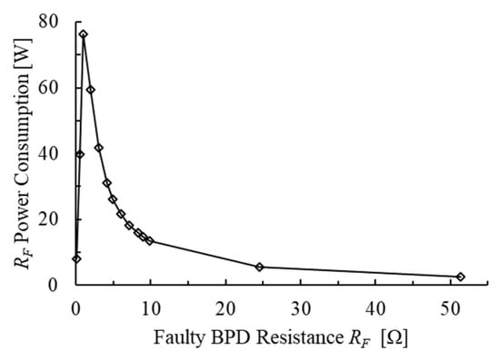
Figure 8.
Relationship between the power dissipated in a failed BPD (RF) and its fault resistance under open-circuit load conditions (simulation).
SBDs are often used as BPDs, and their failures because of the overvoltage caused by lightning strikes have been frequently reported [17]. As SBDs have lower peak reverse voltages than those of PN junction diodes, they are more vulnerable to lightning strikes. The rated forward current of diodes commonly used as BPDs is approximately 15–30 A; however, to reduce the frequency of failures caused by lightning strikes, the use of PN junction diodes or SiC-SBDs with higher peak reverse voltage tolerances and rated forward currents exceeding 30 A is considered effective.
If the thermal design of the junction box that houses the BPD is unsatisfactory, it may promote failures due to long-term current conduction of the BPD or burnout after failure. Therefore, improvement of the thermal design of the junction box is also considered to contribute to reducing the risk of burnout from BPD failure. Ambient temperature is also expected to influence the magnitude and location of maximum power dissipation in a failed BPD. Higher module temperatures generally reduce the open-circuit voltage while slightly increasing the current, which may shift the fault resistance corresponding to peak power dissipation and alter its intensity. Although ambient temperature effects were not explicitly modeled in this study, the proposed framework can incorporate temperature-dependent PV parameters to evaluate thermal risk under different environmental conditions.
In this study, the output characteristics of PV modules with BPD failure and module strings including PV modules with failed BPDs, as well as the power dissipated in the failed BPDs, were successfully captured through numerical simulations. This simulation model is expected to be applicable not only to the evaluation of burnout risk caused by BPD failure but also the safety design of PV modules.
5. Conclusions
In this study, a numerical simulation model was developed to reproduce the operation of PV modules containing failed bypass diodes (BPDs) and series-connected PV module strings, and its validity was verified through comparison with experimental results. The proposed model captured the I–V characteristics under BPD failure conditions as well as the power dissipated in the failed BPD, demonstrating its applicability for evaluating output degradation and thermal risk under practical operating conditions.
Quantitative analysis revealed that, during maximum power-point operation, the heat generated in a failed BPD strongly depends on the fault resistance. The results show that, under maximum power-point operation, the fault resistance at which BPD heating becomes critical depends on the PV string configuration. As additional modules are connected in series, the fault resistance corresponding to peak power dissipation shifts toward higher values, while its magnitude decreases for the representative PV module strings examined in this study.
Furthermore, it was confirmed that under load-release conditions, such as those caused by power-conditioner abnormalities or intentional disconnection during inspection, the power dissipated in a failed BPD increases substantially. This results in a substantially higher risk of burnout compared with normal maximum power-point operation. Although BPD failure can be influenced by multiple factors, the results suggest that external disturbances such as overvoltage stress and temperature rise play an important role. From this perspective, the adoption of diodes with higher voltage withstand capability and larger current ratings, together with improved thermal management of the junction box, is expected to reduce the risk of overheating and burnout following BPD failure.
Overall, the simulation model developed in this study provides a practical and quantitative tool for evaluating the electrical behavior and thermal risk of PV modules and module strings containing failed BPDs. The flexibility of the model allows its adaptation to PV systems with different module ratings and operating conditions, enabling comparative evaluation of system-level trends in electrical behavior and thermal risk. While the present study does not provide an exhaustive parametric analysis across all possible configurations, the proposed framework supports safety assessment, maintenance planning, fault diagnosis, and design optimization within the scope of representative PV module string configurations.
Author Contributions
Conceptualization, I.K. and T.H.; methodology, I.K., I.N., N.I., M.F., S.O. and T.H.; software, I.K. and I.N.; validation, I.K. and T.H.; resources, T.H.; data curation, I.K. and T.H.; writing—original draft preparation, I.K., I.N., N.I., M.F., S.O. and T.H.; writing—review and editing, I.K., I.N., N.I., M.F., S.O. and T.H.; supervision, T.H.; project administration, T.H.; funding acquisition, T.H. All authors have read and agreed to the published version of the manuscript.
Funding
This research received no external funding.
Data Availability Statement
The original contributions presented in this study are included in the article. Further inquiries can be directed to the corresponding author.
Conflicts of Interest
The authors declare no conflicts of interest.
References
- Masson, G.; de l’Epine, M.; Kaizuka, I.; Okazaki, J. Trends in Photovoltaic Applications 2025; IEA PVPS: Paris, France, 2025. [Google Scholar]
- REN21. Global Status Report 2025 (GSR 2025)—Global Overview; REN21: Paris, France, 2025. [Google Scholar]
- Kumar, P.U.; Ippili, V.; Kishore, T.S. Review of global sustainable solar energy policies: Significance and impact. Innov. Green Dev. 2025, 4, 100224. [Google Scholar] [CrossRef]
- Joshi, P.; Rao, A.B.; Banerjee, R. Review of solar PV deployment trends, policy instruments, and growth projections in China, the United States and India. Renew. Sustain. Energy Rev. 2025, 213, 115436. [Google Scholar] [CrossRef]
- Rajput, P.; Singh, D.; Singh, K.Y.; Karthick, A.; Shah, M.A.; Meena, R.S.; Zahra, M.M.A. A comprehensive review on reliability and degradation of PV modules based on failure modes and effect analysis. Int. J. Low-Carbon Technol. 2024, 19, 922–937. [Google Scholar] [CrossRef]
- Aghaei, M.; Fairbrother, A.; Gok, A.; Ahmad, S.; Kazim, S.; Lobato, K.; Oreski, G.; Reinders, A.; Schmitz, J.; Theelen, M.; et al. Review of degradation and failure phenomena in photovoltaic modules. Renew. Sustain. Energy Rev. 2022, 159, 112160. [Google Scholar] [CrossRef]
- Koester, D.; Lindig, S.; Louwen, A.; Astigarraga, A.; Manzolini, G. Review of photovoltaic module degradation, field inspection techniques and techno-economic assessment. Renew. Sustain. Energy Rev. 2022, 155, 112616. [Google Scholar] [CrossRef]
- Jordan, D.C.; Kurtz, S.R. Photovoltaic degradation rates—An analytical review. Prog. Photovolt. 2013, 21, 12–29. [Google Scholar] [CrossRef]
- Koentges, M.; Kurtz, S.; Packard, C.; Jahn, U. Review of Failures of Photovoltaic Modules; Photovoltaic Power Systems Program; Report IEA-PVPS T13-01; IEA PVPS: Paris, France, 2014. [Google Scholar]
- Wu, Z.; Hu, Y.; Wen, J.X.; Zhou, F.; Ye, X. A Review for Solar Panel Fire Accident Prevention in Large-Scale PV Applications. IEEE Access 2020, 8, 132466–132480. [Google Scholar] [CrossRef]
- Alimi, O.A.; Meyer, E.L.; Olayiwola, O.I. Solar Photovoltaic Modules’ Performance Reliability and Degradation Analysis—A Review. Energies 2022, 15, 5964. [Google Scholar] [CrossRef]
- Yang, H.Y.; Zhou, X.D.; Yang, L.Z.; Zhang, T.L. Experimental Studies on the Flammability and Fire Hazards of Photovoltaic Modules. Materials 2015, 8, 4210–4225. [Google Scholar] [CrossRef] [PubMed]
- Oke, S.; Sakai, H.; Tottori, H.; Shimizu, Y.; Choo, N.; Nanno, I.; Fujii, M. I-V Characteristics of Broken Bypas Diode on PV module. In Proceedings of the 35th EU-PVSEC, Brussels, Belgium, 24–28 September 2018; pp. 1996–2000. [Google Scholar]
- Hamada, T.; Azuma, T.; Nanno, I.; Ishikura, N.; Fujii, M.; Oke, S. Impact of Bypass Diode Fault Resistance Values on Burnout in Bypass Diode Failures in Simulated Photovoltaic Modules with Various Output Parameters. Energies 2023, 16, 5879. [Google Scholar] [CrossRef]
- Bishop, J.W. Computer simulation of the effects of electrical mismatches in photovoltaic cell interconnection circuits. Sol. Cells 1988, 25, 73–89. [Google Scholar] [CrossRef]
- Villalva, M.G.; Gazoli, J.R.; Filho, E.R. Comprehensive Approach to Modeling and Simulation of Photovoltaic Arrays. IEEE Trans. Power Electron. 2009, 24, 1198–1208. [Google Scholar] [CrossRef]
- Hamada, T.; Nakamoto, K.; Nanno, I.; Ishikura, N.; Oke, S.; Fujii, M. Characteristics of Failed Bypass Diodes for Photovoltaic Module by Artificial and Natural Lightning. In Proceedings of the International Symposium on High Voltage Engineering, Budapest, Hungary, 26–30 August 2019; Volume 598, pp. 1218–1224. [Google Scholar]


Disclaimer/Publisher’s Note: The statements, opinions and data contained in all publications are solely those of the individual author(s) and contributor(s) and not of MDPI and/or the editor(s). MDPI and/or the editor(s) disclaim responsibility for any injury to people or property resulting from any ideas, methods, instructions or products referred to in the content. |
© 2026 by the authors. Licensee MDPI, Basel, Switzerland. This article is an open access article distributed under the terms and conditions of the Creative Commons Attribution (CC BY) license.