Abstract
This study presents an integrated experimental–modeling investigation of the thermal behavior of a multistage centrifugal refrigerant pump in solar ejector refrigeration systems (SERS). A temperature-rise prediction model is formulated strictly from energy conservation with viscous dissipation and validated on a closed-loop test rig under variable flow rates, inlet pressures, and operating frequencies. Experiments show that the outlet temperature rise (ΔT) decays approximately exponentially with increasing flow rate, while higher operating frequency intensifies viscous-dissipation heating. The pressure difference (Δp) increases with both flow rate and frequency, whereas the overall efficiency (η) exhibits a parabolic trend, peaking at 32.6% at 37.5 Hz. The model achieves high predictive accuracy, with errors within ±0.4 °C at 25–37.5 Hz and about ±1.1 °C at 50 Hz. By constructing Δp–Q–f operating maps and coupling them with cavitation-risk analysis, safe and optimal operating zones (“best zone” and “caution zone”) are identified. These results provide quantitative guidance for pump thermal management, frequency scheduling, and system integration, enabling energy-efficient and reliable operation of solar-driven ejector refrigeration systems.
1. Introduction
Against the backdrop of China’s “dual-carbon” strategy—peaking carbon emissions before 2030 and achieving carbon neutrality before 2060—solar energy, a clean and renewable resource, has attracted increasing attention for its efficient application to building heating and cooling [1]. Solar ejector refrigeration systems (SERS) are capable of using low-grade heat sources (such as solar thermal energy or industrial waste heat) to provide cooling, featuring simple structure, adaptability, and environmental sustainability [2]. In recent years, notable progress has been achieved in ejector modeling [3], solar thermal integration [4], and hybrid cycle improvement [5], which has demonstrated the potential of SERS in terms of energy efficiency and operational stability. Meanwhile, low global warming potential (low-GWP) refrigerants such as R1233zd(E) and R1234ze(Z), owing to their favorable thermophysical and environmental properties, have gradually become mainstream choices for ejector and high-temperature cooling applications [6,7]. These trends highlight the necessity of re-examining component-level operating characteristics in modern SERS cycles, particularly the performance of pumps under low-pressure refrigerant conditions.
Unlike conventional vapor-compression systems in which compressors provide the driving power, thermally driven systems such as ejector refrigeration and organic Rankine cycles (ORCs) rely on liquid pumps to pressurize and circulate refrigerants [8]. In SERS, the multistage centrifugal pump serves as the only active power component. Its operating performance not only determines the circulation flow rate and pressure difference but also directly influences pump power consumption and the overall system coefficient of performance (COP/EER) [9]. Existing studies have primarily analyzed pump hydraulic performance or efficiency variation from a turbomachinery perspective, while relatively little attention has been paid to the conversion of internal energy losses into temperature rise [10]. A few related works have employed conventional energy conservation or similarity principles to construct prediction models, assuming that all losses are converted into sensible heating of the working fluid. However, this assumption neglects mechanical friction, casing heat dissipation, and realistic boundary conditions, limiting the applicability of such models in engineering scenarios [11]. In SERS, pump-induced temperature rise reduces the refrigerant’s effective subcooling and adds sensible heat to the loop; both effects can deteriorate ejector entrainment and increase condenser duty, thereby lowering system coefficient of performance (COP) and energy efficiency ratio (EER) under off-design conditions.
The operating state of the refrigerant pump is critical to the thermal performance and stability of SERS. Under off-design conditions such as low flow rate or high pressure difference, pumps often encounter severe efficiency degradation, significant heat accumulation, and cavitation [12]. Prolonged occurrence of these issues may trigger local vaporization within the pump, leading to mechanical wear, corrosion, vibration, noise, and potentially catastrophic failure or unplanned shutdowns. Therefore, a deeper understanding of the temperature rise characteristics, efficiency variation, and cavitation mechanisms of refrigerant pumps under variable operating conditions is not only essential for pump design optimization but also vital for improving system efficiency and long-term reliability [13].
In recent years, several scholars have investigated pump behavior under partial-load and extreme conditions. Sojoudi et al. [14] experimentally revealed nonlinear relationships between fluid temperature rise and rotational speed during non-full-load operation of centrifugal pumps, finding a strong correlation between heat accumulation and impeller energy dissipation. Recent visualization and CFD studies have clarified the internal mechanisms behind temperature rise and efficiency loss at part-load. Ye et al. identified unstable flow features—recirculation near the inlet and blade-edge separation—in a centrifugal pump and showed that tailoring the trailing-edge geometry alleviates these instabilities, thereby reducing hydraulic losses that convert into sensible heating [15]. Extending the geometric perspective, Jia et al. demonstrated that changing the volute area ratio reshapes the internal three-dimensional flow and noise characteristics, implying a strong geometry–loss–ΔT linkage under off-design conditions [16]. Focusing on the blade leading edge, Chen et al. compared alternative rounding radii and inlet profiles and found that proper leading-edge design weakens separation, improves external characteristics, and widens the stable operating window—an effective structural lever to curb local heat accumulation [17]. For refrigerant pumps specifically, Fang et al. combined simulation and experiments on an R134a self-lubricating centrifugal pump, reporting hydraulic performance and cavitation characteristics that corroborate the observed off-design penalties and their connection to temperature rise [18].
At the system level, simplified models still frequently impose constant pump efficiencies: early TRNSYS practice set pump efficiency as a fixed value or user-defined polynomial for year-round simulations [19], and recent SERS pre-cooling analyses likewise employed nominal efficiencies for component blocks [20]. In contrast, prototype data reveal large, load-dependent deviations from such assumptions. Rosset et al. measured small-scale ORC performance and reported that the commercial pump’s overall efficiency remained low under realistic operating ranges [21]. Under variable condensing conditions, Wang et al. analyzed ORC pump control and showed that operating point and scheduling materially affect achievable efficiencies (typically well below idealized constants) [22]. For micro-scale machines, Fatigati et al. coupled a physics-based sliding-vane pump model with experiments and demonstrated that leakage–friction competition, fluid viscosity and shaft speed jointly cap volumetric and overall efficiencies—highlighting the risk of performance over-prediction with fixed values [23]. Collectively, these findings motivate replacing static assumptions by Δp–Q–f operating maps and cavitation-aware constraints, integrated with frequency scheduling.
Cavitation is another critical issue in ejector refrigeration systems. Compared with water pumps, refrigerants—with their lower saturation temperatures, smaller latent heats, and higher vapor pressures—are more susceptible to local vaporization inside the pump, leading to bubble formation and collapse. This process can damage impellers and seals, induce fatigue failure, and destabilize the system. Cavitation not only alters the head–flow characteristics but also drastically reduces efficiency and service life. Therefore, effective suppression of cavitation through structural and thermal strategies has become a pressing engineering challenge.
For low-boiling refrigerants, cavitation is governed by the coupled hydrodynamic–thermodynamic mechanism: phase-change heat absorption induces local temperature depression and lowers the local saturation pressure, thereby modifying cavitation inception and extent (in addition to the hydrodynamic NPSH/σ effects). Using a Venturi setup with R134a, Zhang et al. time-resolved the formation–collapse dynamics of cavitation clouds and quantified their correlation with local temperature depression, providing a more accurate basis for sizing inlet head and effective subcooling to maintain stable suction [24]. On the component/system interface, Zhang H. et al. jointly optimized a two-phase steam ejector with CFD–RSM–GA, ranking geometric and operating sensitivities and delineating the stable domain that can be mapped to pump “safe-suction” regions [25]. From a cycle standpoint, experiments on ejector refrigeration and ejector-cascade configurations show that appropriate integration (e.g., adding a regenerator) improves COP/exergy efficiency under identical boundaries, effectively relaxing downstream head requirements and broadening feasible operating windows [26,27]. In ORC-coupled applications, multistage pump performance also varies with condensation conditions, reinforcing the need to co-design suction margin with system constraints [28]. Taken together, the evidence supports a joint control policy in SERS that treats the minimum sustainable flow, NPSH/subcooling margin, and frequency scheduling (Δp–Q–f) as coupled constraints rather than static limits on any single component.
From a system integration perspective, variable frequency drives (VFDs) are widely recognized as effective tools for reducing pump energy consumption by matching power with demand. However, there remains no clear control guideline on how to simultaneously account for temperature rise penalties, pressure difference requirements, and cavitation constraints during frequency scheduling. Industrial pump energy-saving studies have shown significant potential benefits of VFD operation, but in refrigeration cycles pumps must simultaneously (1) provide the required pressure difference for ejectors and condensers, (2) maintain sufficient cavitation margin, and (3) minimize internal heating to avoid COP reduction. The trade-offs among these objectives currently lack practical models and experimental validation.
Based on the above review, the following gaps can be identified: (1) absence of control-oriented pump temperature rise models that balance simplicity and physical realism, as most existing studies remain at the idealized “adiabatic assumption” level without external dissipation or boundary condition corrections; (2) lack of comprehensive multistage pump experimental data covering the full spectrum of variable frequency, flow rate, and inlet pressure, particularly under low-pressure refrigerant cycles; (3) lack of cavitation-aware operating maps for low-GWP refrigerants, which hinders reliable engineering operation boundaries; and (4) lack of quantitative coupling analysis between pump behavior and system-level performance indicators (COP/EER), leaving frequency optimization, operational scheduling, and system integration without direct guidance.
This study addresses the above issues through the following contributions: (i) establish a pump temperature-rise model based on energy conservation with viscous dissipation, capable of predicting ΔT under variable frequencies and operating conditions; (ii) conducting systematic experimental tests on a low-pressure refrigerant multistage VFD pump to analyze the coupled relationships among temperature rise, pressure difference, power, and efficiency; (iii) constructing Δp–Q–f operating maps based on experimental data, and identifying “best” and “caution” zones through cavitation risk analysis; and (iv) examining the influence of pump operation on SERS energy performance and scheduling strategies, proposing optimization recommendations. By integrating theory, experiment, and system-level perspectives, this work provides a quantitative foundation for the design and control optimization of refrigerant pumps in solar-driven systems, contributing to enhanced performance and long-term reliability of ejector refrigeration systems.
2. Theoretical Analysis
At present, multistage pumps are widely employed in organic Rankine cycles (ORCs) for liquid refrigerant delivery, and centrifugal pumps are increasingly replacing diaphragm pumps in ejector refrigeration systems owing to their simple operation, cost-effectiveness, and practical applicability. In this study, a vertical multistage centrifugal pump (model 25CDLF1-36) was selected. The pump is designed for a maximum working pressure of 25 bar, with an allowable fluid temperature range of −15 to 70 °C and a maximum ambient temperature of 40 °C. The rated motor power is 2.2 kW. The recommended operating ranges of flow rate and pressure head are summarized in Table 1, while the detailed motor performance parameters are presented in Table 2.

Table 1.
The parameters of the pump.
Table 2.
Performance Parameters of Multistage Centrifugal Pump Motor.
For the experimental evaluation, the design parameters of the multistage centrifugal pump were matched with the operating range of the solar ejector refrigeration system. The basic boundary conditions were defined by a generator temperature of Tg = 85 °C and a condenser temperature of Tc = 35 °C. Refrigerant R142b was selected as the working fluid, and both theoretical analysis and experimental studies were carried out to investigate its performance within the multistage centrifugal pump. Refrigerant R142b was selected as the working fluid for the following reasons. First, it ensures continuity and comparability with our previous studies on the same closed-loop rig under identical instrumentation and piping, thereby isolating apparatus-related effects. Second, within the condenser-temperature and inlet-pressure ranges explored here, R142b remains stably liquid with moderate saturated vapor pressure, viscosity, and density; this provides a sufficient NPSH margin to mitigate cavitation and yields a clearly measurable outlet temperature rise (ΔT) for reliable uncertainty analysis. Third, R142b is compatible with the pump’s sealing materials and sensors, and its thermophysical properties are well documented in open sources, facilitating calibration and reproducibility. Fourth, our dimensionless correlation explicitly accounts for fluid properties (e.g., ρ, μ, cp), so the model and conclusions do not depend on a specific refrigerant; R142b serves as a baseline/surrogate dataset for subsequent cross-validation with low-GWP refrigerants (e.g., R245fa, R1233zd(E), R1234ze(Z)). Finally, all experiments were performed in a small-charge, sealed loop with appropriate safety measures.
2.1. Analytical Approach for Temperature Rise in Centrifugal Pump
During continuous operation of a centrifugal pump delivering refrigerant, internal power losses inevitably cause a rise in the temperature of the working fluid. This thermal increase may result in pump overheating and cavitation. Overheating not only shortens the service life of mechanical seals but also enhances the corrosiveness of the fluid. Cavitation, in contrast, leads to deterioration of pump performance, efficiency reduction, and severe damage to internal hydraulic components, while simultaneously inducing vibration and noise.
It should also be noted that, under certain process requirements, when no suitable centrifugal pump for small flow rates is available, pumps are often forced to operate for extended periods under low-flow conditions. In such cases, determining the minimum continuous thermal control flow rate becomes essential. This parameter refers to the lowest flow rate at which the pump can operate without suffering adverse effects from fluid temperature rise.
When operating at low flow rates, the overall pump efficiency decreases sharply, leading to a higher rate of energy loss. From this perspective, an energy balance can be established to relate the loss rate to the fluid temperature increase from the suction inlet to the discharge nozzle. This balance holds true under the assumption that the pump is perfectly thermally insulated and that all internal losses are entirely converted into heat, which then increases the fluid temperature.
where LR is the loss rate, AH is the absorbed heat by the working fluid, η is the overall efficiency, P is the input power to the pump, m is the fluid mass flow rate, Cp is the specific heat of the fluid, and ΔT is the temperature rise.
Equating Equations (1) and (2) gives:
where Q, H and c are flow rate (m3/s), head (m) and specific weight (kg/m2·s2). Using Equations (3) and (4), we can write:
Finally, solving for ΔT:
where ρ is the fluid density (kg/m3), Q is the volumetric flow rate (m3/s), H is the pump head (m), γ is the specific weight (kg/m2·s2), and g is gravitational acceleration (m/s2).
This theoretical relation estimates the fluid temperature rise using overall pump efficiency. It assumes that all categories of hydraulic, volumetric, and mechanical losses are converted into thermal energy. As such, it represents a conservative prediction, providing the maximum expected temperature rise under part-load operation of centrifugal pumps. In reality, however, part of the dissipated energy is transferred to the environment through average convective heat transfer, which varies with pump size and geometry, and therefore this maximum rise cannot be fully realized in practical applications.
2.2. Scale Analysis by Dimensionless Groups
All influential parameters affecting the pump temperature rise can be identified based on the theoretical relations derived in the previous section and the present experimental framework. These parameters include: fluid density ρ [kg/m3], specific heat capacity Cp [J/(kg·K)], dynamic viscosity μ [Pa·s], flow rate Q [m3/s], impeller outlet diameter D2 [m], pump head H [m], and gravitational acceleration g [m/s2]. Accordingly, the temperature difference between inlet and outlet flows can be expressed as a functional relation of these variables:
Neglecting variations in fluid properties and pump efficiency, the proportional (affinity) laws describing the relationship between pump flow, head, shaft power, and rotational speed can be expressed as:
where Q, H, P, respectively, represent the pump flow, pressure head, shaft power when the speed is n. Q′, H′, P′, respectively, represent the pump flow, pressure head, shaft power when the speed is n′.
Based on the similarity laws, the functional relationship between temperature rise and rotational speed can be written as:
Assuming constant efficiency (η′ = η), Equation (11) simplifies to:
This result shows that the temperature rise is related to the pump power, flow rate, and efficiency, and is directly proportional to the square of the rotational speed. Therefore, the functional relationship between pump temperature rise and rotational speed can be approximated as a quadratic dependence.
3. Experimental System Design for Multistage Pump Thermal Performance
3.1. Experimental System Design
According to long-term meteorological statistics, the outdoor ambient temperature in Zhengzhou during the cooling season (May–October) typically ranges from 25 °C to 40 °C. Based on this climatic profile, the condensing temperature of the solar ejector refrigeration system was set within the same range (25–40 °C), corresponding to a refrigerant saturation pressure of 0.338–0.523 MPa [29]. This pressure range was adopted as the controllable inlet pressure boundary for the refrigerant pump during the experiments.
To realistically replicate the operating behavior of the multistage centrifugal pump within a solar ejector refrigeration system, the test conditions were configured to reflect typical system dynamics. Specifically, the pump inlet pressure was set equal to the condenser outlet pressure, while the volumetric flow rate and rotational speed were varied across representative values. A comprehensive experimental matrix was established by systematically adjusting four key variables: inlet pressure, flow rate, rotational speed, and the inlet–outlet temperature difference in the refrigerant pump.
The schematic of the experimental setup is presented in Figure 1, outlining the integrated flow loop of the working fluid pump system. The corresponding physical implementation of the test platform is shown in Figure 2, including major components such as the water-cooled condenser, electric preheater, pump controller, and measurement instrumentation.

Figure 1.
Flow diagram of working fluid pump test platform. T1, T2, T3, T4, T5, T6 are the temperature measurement points, and P1, P2, P3, P4 are the pressure measurement points.

Figure 2.
Experimental apparatus of the refrigerant pump performance test system.
The experimental platform consists of a closed-loop refrigerant-pump rig, a data-acquisition system, and an electrical control unit. The closed loop comprises two subcircuits: a refrigerant circuit and a water circuit.
In the refrigerant circuit, the main components are a multistage refrigerant pump, a double-pipe (sleeve) heat exchanger operating in counter-flow, a receiver, and a conical globe valve. Sight glasses are installed at the pump inlet, the mass flowmeter inlet, and at the outlet of the double-pipe heat exchanger to observe the working fluid state. After charging an appropriate amount of refrigerant, the pump inlet pressure is maintained by adjusting the temperature of the cooling water supplied by the thermostatic bath.
The water circuit includes a thermostatic water bath, the double-pipe heat exchanger, a water pump, ball valves, and a flowmeter. Tap water first enters the thermostatic bath, which stabilizes the water temperature and thereby indirectly stabilizes the pressure of the refrigerant loop. Once the set temperature is reached, the water pump delivers the water to the heat exchanger; a ball valve at the pump outlet regulates the flow, and an electromagnetic flowmeter is installed downstream after the required straight-pipe run.
The data-acquisition system consists of a DAQ unit together with electronic measuring instruments and auxiliary precision anti-vibration mechanical (Bourdon) pressure gauges. The instrumentation includes pressure and differential-pressure transmitters, a refrigerant mass flowmeter, a water-side flowmeter, a power meter, and K-type thermocouples. The mechanical pressure gauges facilitate convenient pressure adjustment, provide a cross-check against the transmitter readings, and act as a fail-safe in case of unnoticed electronic malfunctions. Power-meter signals are collected using KingView (SCADA) 7.50 software, while the other measurement signals are acquired with Keithley digital multimeters; automated acquisition is coordinated by a computer.
Throughout the experiments, key performance metrics—including outlet pressure, electrical power consumption, overall pump efficiency, flow rate, and thermal characteristics—were continuously monitored and recorded. By analyzing the variation in these parameters under different operating conditions, the optimal working envelope of the refrigerant pump was identified. This operating window provides a practical reference for system design, aiding in pump selection, system integration, and performance optimization, particularly under variable-speed control strategies for energy-efficient operation.
3.2. Error Analysis
The testing process is influenced by multiple factors, and therefore measurement errors are inevitable. Although various measures were taken to improve accuracy, the recorded values can only approximate the true values. Following Moffat’s error analysis approach, namely the “method of propagation of uncertainties” (also referred to as the power-of-two method), the uncertainty of the experimental data was evaluated. Based on the overall efficiency of the refrigerant pump, the uncertainty in pump efficiency was calculated by considering motor efficiency, with the measurement accuracy of the motor specified as grade 0.2. Table 3 summarizes the instrumentation—measuring points, parameters, measurement ranges, and accuracies—used in the refrigerant and water circuits; these specifications underpin the uncertainty analysis described above.
Table 3.
Sensor parameters.
According to the pump manual, the characteristic curves of the selected pump were obtained at a fixed motor speed of 2900 rpm (50 Hz) under standard reference conditions (ambient pressure, water at 20 °C, free of air, and kinematic viscosity of 1 mm2/s). As the flow rate increases, the pump head decreases gradually. The pump efficiency and overall efficiency (including motor losses) initially increase and then decrease, reaching maximum values of 44.0% and 37.2%, respectively, within the flow range of 1.4–2.0 m3/h, which is higher than the rated flow rate. The relatively low total efficiency reflects high energy consumption, which can be attributed to the high-head and low-flow operating conditions as well as the intrinsic design characteristics of the pump.
Measurement Uncertainty. The uncertainties of the measurement instruments used in this study are as follows:
- (1)
- Pressure sensors: accuracy ±0.5%, signal acquisition uncertainty 0.11%, total uncertainty 0.61%.
- (2)
- Differential pressure transmitters: accuracy ±0.075%, total uncertainty 0.185%.
- (3)
- Mass flowmeter: range 0–3500 kg/h, accuracy ±0.1%, total uncertainty 0.71%.
- (4)
- Density estimation: derived from pressure and temperature, verified against the flowmeter, uncertainty ~1.67%.
- (5)
- Electromagnetic flowmeter: accuracy ±0.35%, total uncertainty 0.46%.
- (6)
- Power meter: accuracy ±0.5%, total uncertainty 0.61%.
- (7)
- Temperature (K-type thermocouple): accuracy ±0.2 °C, total uncertainty 0.5 °C.
Based on the above analysis, the overall uncertainty of useful pump power is estimated at ±3.76%, while the uncertainty of total pump efficiency is approximately ±3.86%.
4. Results and Discussion
4.1. Recommended Operating Region of the Refrigerant Pump Under Variable Conditions
Figure 3 presents a heatmap of differential pressure (Δp) as a function of flow rate (Q) for four typical operating frequencies (25, 37.5, 50, and 60 Hz). The color scale represents the magnitude of Δp, while blue stars indicate the pressure difference window required by solar ejector refrigeration systems (0.725–1.375 MPa under typical generation and condensation conditions). The ‘caution zone’ is identified from inflections/irregularities in the Δp–Q–f maps, concurrent ΔT amplification, and the approach of NPSHa to the system requirement window; it serves as an operational warning, while quantitative NPSHr–f and σc mapping are left for future work.

Figure 3.
Heatmap of differential pressure (Δp) versus flow rate (Q) at different operating frequencies (pc = 0.454 MPa).
At 37.5 Hz, Δp consistently falls within the design-compliant (required) operating window across a broad flow range, indicating that the pump can meet system requirements without inducing excessive hydraulic losses or thermal accumulation; therefore, 37.5 Hz is recommended as the baseline frequency for system design and control. This indicates that the pump can provide sufficient head to meet system requirements without inducing excessive internal hydraulic losses or thermal accumulation. The wide stability margin at this frequency ensures reliable operation under variable load conditions, making it the most suitable baseline frequency for system design and control.
At 50 Hz and especially 60 Hz, Δp values significantly exceed the required window. Although this suggests stronger pressure capacity, it results in overperformance relative to system demand. The excess pressure head translates into additional shaft work and higher frictional dissipation, which accelerate temperature rise inside the pump. Consequently, the risk of thermal inefficiency, cavitation onset, and accelerated wear of sealing components becomes more pronounced. This regime therefore represents a “caution zone” where continuous operation should be avoided unless additional throttling or control mechanisms are implemented.
At 25 Hz, Δp falls below the required range over most of the flow domain. The insufficient head directly limits refrigerant circulation capacity, potentially leading to unstable ejector entrainment ratios and degraded system COP. This regime is therefore unsuitable for reliable ejector refrigeration operation.
By integrating these observations, it is evident that 37.5 Hz offers the best trade-off between hydraulic performance and thermal stability. This operating frequency not only aligns with the system’s pressure requirements but also minimizes unnecessary energy dissipation and thermal penalties. Defining such an “optimal zone” and contrasting it with the “caution zones” of under- and overperformance provides quantitative guidance for frequency scheduling, pump control strategies, and long-term reliability optimization in solar ejector refrigeration systems.
4.2. Experimental Analysis of Temperature Rise, Pressure Difference and Efficiency Under Varying Flow Rates (50 Hz)
Figure 4 illustrates the variation in pump inlet–outlet temperature difference (ΔT), pressure difference (Δp), and overall efficiency (η) with flow rate at an operating frequency of 50 Hz and inlet pressure of 0.454 MPa. The left-hand plot compares the experimental results with the theoretical calculations for temperature rise.
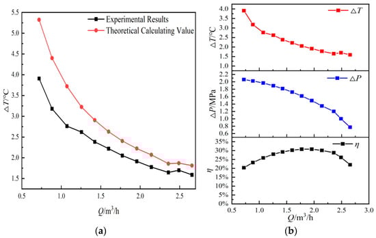
Figure 4.
(a) Comparison between the theoretical temperature-rise prediction and the experimental measurement (ΔT). (b) Experimental variations in temperature rise (ΔT), pressure difference (Δp), and pump overall efficiency (η) with flow rate under 50 Hz operation (inlet pressure = 0.454 MPa).
It can be observed that the temperature difference decreases significantly as the flow rate increases, especially in the low-flow region (Q ≤ 1.2 m3/h), where the decline is steep. In the higher flow range, the reduction in ΔT becomes more gradual. The experimental values are generally lower than the theoretical predictions, which can be attributed to real-world thermal losses and non-ideal heat exchange conditions.
The middle and right plots show that the pressure difference decreases with increasing flow rate, while the overall efficiency first increases, reaching a peak at approximately 1.6–1.8 m3/h, and then declines. This flow range can thus be identified as the optimal efficiency zone.
These results indicate that under low-flow operating conditions, the pump experiences higher thermal buildup and lower efficiency, making it more prone to refrigerant cavitation and performance instability. Therefore, careful flow rate control is essential to avoid operating outside the pump’s stable and efficient range.
4.3. Influence of Inlet Pressure on Pump Performance Characteristics (50 Hz)
Figure 5 presents the performance characteristics of the refrigerant pump under three inlet pressures: 0.393 MPa, 0.454 MPa, and 0.523 MPa, corresponding to condensing temperatures of 30 °C, 35 °C, and 40 °C, respectively.

Figure 5.
Flow rate-dependent variation in pump performance (a) and theoretical vs. experimental temperature rise (b) under different inlet pressures (f = 50 Hz).
From Figure 5a, the following quantitative observations can be made: Within the recommended operational range (0.4–2.0 m3/h), the maximum differential pressure increases by up to 0.36 MPa, indicating an 86% rise from the lowest inlet pressure condition. This reflects the direct influence of condensing pressure on overcoming system resistance. Pump total efficiency peaks between 1.5 and 2.0 m3/h, with maximum values reaching 7.9%, 8.5%, and 8.7% for increasing inlet pressures. The variation is moderate, suggesting a limited yet positive impact of pressure on pump efficiency. Power consumption increases rapidly with both inlet pressure and flow rate, which may present challenges for energy optimization in solar ejector systems.
In Figure 5b, the temperature rise trends show: In the low-flow region (Q < 1.2 m3/h), the temperature rise increases sharply, with a maximum of 5.3 °C observed at the highest inlet pressure, indicating significant thermal accumulation due to slower fluid movement. For Q > 2.0 m3/h, both the temperature rise and efficiency curves exhibit irregularities, suggesting the onset of flow separation or cavitation effects. Taken together, the results identify 2.0 m3/h as a critical flow threshold beyond which pump operation becomes unstable, characterized by performance degradation and nonlinear response. These behaviors may stem from recirculation zones or vapor formation at the pump inlet. It is therefore recommended to constrain the working flow range to 0.6–1.8 m3/h for optimal performance and system reliability.
4.4. Analysis of Temperature Rise and Performance Characteristics Under Variable Speeds (Inlet Pressure = 0.454 MPa, Condensation Temperature = 35 °C)
Figure 6 systematically depicts the effects of pump rotational speed on thermal and hydraulic performance by comparing the outlet temperature rise (ΔT), pressure difference (Δp), and overall efficiency (η) at three representative operating frequencies—25 Hz, 37.5 Hz, and 50 Hz—under a fixed inlet pressure of 0.454 MPa (subplot axes follow the valid experimental range at each frequency). These frequencies correspond to partial-load, nominal, and high-load operation states commonly encountered in solar ejector refrigeration systems driven by variable-speed photovoltaic or thermal sources.

Figure 6.
Experimental comparison of outlet temperature rise versus flow rate at an inlet pressure of 0.454 MPa under different operating frequencies (25 Hz (a), 37.5 Hz (b), and 50 Hz (c)).
As shown in Figure 6a–c, ΔT exhibits a monotonic decline as flow rate increases across all frequencies. This inverse relationship is attributed to the reduced residence time of the working fluid within the pump chamber at higher flow rates, which limits internal energy dissipation from viscous and mechanical effects. Notably, at 50 Hz, the initial ΔT reaches up to 5.3 °C at low flow (Q ≈ 0.6 m3/h), but drops sharply to 1.2 °C at Q = 2.8 m3/h. Such substantial thermal attenuation under high-speed operation suggests enhanced convective cooling but also implies increased mechanical workload and potential cavitation risk.
The pressure difference (Δp) increases significantly with rotational frequency, showing a steep positive gradient across the same flow range. At 25 Hz, Δp peaks below 0.72 MPa, whereas at 50 Hz, Δp exceeds 1.35 MPa—representing an 88.3% increase. This sharp rise in pressure capability reflects the strong dependence of kinetic head on impeller speed, validating the applicability of centrifugal pump similarity laws. The data also confirm that speed regulation is an effective means to modulate the pump’s discharge head to match varying system load demands, particularly under solar irradiation fluctuation.
The pump efficiency (η) curves display a distinct parabolic shape at each frequency, with the maximum efficiency attained at 37.5 Hz, peaking at approximately 32.6% in the flow range of 1.4–1.8 m3/h. Compared to both lower and higher frequencies, this medium-speed operation achieves a favorable thermodynamic balance between mechanical energy input and hydraulic output, avoiding the high viscous losses at low speeds and the thermal buildup or frictional drag at higher speeds. These findings suggest that 37.5 Hz represents the optimal operational regime for balancing efficiency and performance stability and is therefore recommended as the baseline control point for subsequent evaluations and system integration.
In summary, the results in Figure 6 highlight the critical role of rotational frequency as a control variable in tailoring pump output to dynamic system conditions. Moderate frequencies offer superior efficiency without compromising thermal or hydraulic performance, supporting intelligent frequency modulation as a strategy for energy-efficient operation in solar ejector refrigeration systems.
Figure 7 illustrates the outlet temperature rise (ΔT) characteristics of the refrigerant pump under varying flow rates and operating frequencies (25 Hz, 37.5 Hz, and 50 Hz), with an inlet pressure fixed at 0.454 MPa. Across all frequencies, ΔT exhibits a clear monotonic decrease as flow rate increases, reflecting enhanced convective heat dispersion at higher flow conditions. Notably, a distinct inflection point appears at Q ≈ 1.8 m3/h, beyond which the ΔT reduction rate flattens—indicating a transition threshold from thermal inefficiency to stabilized flow regimes.

Figure 7.
Comparison of experimental and theoretical outlet temperature rise versus flow rate at an inlet pressure of 0.454 MPa under various frequencies (25 Hz, 37.5 Hz, and 50 Hz).
At equal flow rates, higher frequencies yield lower ΔT values, confirming that increased pump speed promotes both efficiency and thermal stability. For instance, at Q = 1.5 m3/h, ΔT at 50 Hz is approximately 1.3 °C lower than at 25 Hz. The 37.5 Hz condition achieves an optimal trade-off between power consumption and internal heat rise, making it the recommended reference speed for solar ejector refrigeration systems.
The proposed theoretical model demonstrates good agreement with experimental results, with over 85% of points within ±15% deviation. These discrepancies arise from sensor resolution limits, neglected cavitation effects, and hydraulic losses under off-design operation. Nevertheless, the model achieves an RMSE of ±0.13 °C, validating its predictive reliability and its utility in guiding the design of thermal control strategies and safe operating zones.
4.5. Analysis of Pump Performance and Temperature Rise Under Varying Frequencies and Inlet Pressures
Figure 8 comprehensively presents the performance evaluation of the multistage centrifugal refrigerant pump operating at 25 Hz under three typical inlet pressures—0.393 MPa, 0.454 MPa, and 0.495 MPa—corresponding to condensing temperatures of 30 °C, 35 °C, and 38 °C, respectively. These conditions simulate realistic summertime condenser-side saturation states of solar ejector refrigeration systems operating under varying ambient loads.

Figure 8.
Variations in pump performance (a) and temperature rise: experimental vs. theoretical values (b) under different inlet pressures at 25 Hz.
As shown in Figure 8a, the temperature rise across the pump (ΔT) decreases significantly with increasing volumetric flow rate, particularly in the low-flow regime (Q < 0.6 m3/h), where thermal accumulation and irreversible losses dominate due to extended residence time and low turbulence intensity. At higher flow rates, the reduction in ΔT becomes more gradual, indicating enhanced convective heat transfer and reduced energy dissipation. Importantly, the ΔT curves shift slightly downward with increasing inlet pressure, suggesting a subtle reduction in internal thermal buildup at elevated saturation conditions.
The pressure difference (Δp) exhibits a typical declining trend with flow rate due to hydraulic resistance and pump head characteristics. However, Δp remains relatively insensitive to variations in inlet pressure within the tested range, with deviations under 5%. This indicates that the pump’s pressure head is largely governed by rotational speed and internal geometry, rather than external static inlet conditions, under low-frequency operation. The consistent behavior across inlet pressures confirms stable hydraulic performance and predictable pressure delivery in practical applications.
Efficiency (η) follows a parabolic trajectory with respect to flow rate, peaking at approximately 27.1% within the 0.9–1.1 m3/h range. This optimal flow window balances mechanical power input and hydraulic output, highlighting the importance of frequency-flow coordination for achieving energy-efficient refrigerant circulation. Compared to higher-frequency operation, the peak efficiency is slightly lower, which can be attributed to reduced impeller velocity and greater relative friction losses at lower speeds.
Figure 8b compares the experimental and theoretical temperature rise curves under the same three inlet pressure levels. The modeled predictions align closely with measured data, with maximum deviations confined to within ±0.4 °C across all flow rates. The strong agreement validates the accuracy of the thermal modeling approach, including assumptions on fluid properties, boundary conditions, and energy balance formulations. The consistent prediction accuracy also reinforces the model’s applicability to performance forecasting and design optimization under variable operating conditions.
Collectively, the results demonstrate that the pump operates reliably at 25 Hz, delivering stable hydraulic performance and acceptable thermal behavior across a wide range of inlet pressures. This supports its feasibility for low-load or part-load operation modes in solar ejector refrigeration systems, particularly during periods of low solar irradiation or nighttime recovery conditions where low-speed circulation is preferred.
Figure 9 illustrates the performance characteristics of the refrigerant pump at a frequency of 37.5 Hz under varying inlet pressures, corresponding to typical condenser saturation conditions of 30 °C, 35 °C, and 38 °C (i.e., inlet pressures of 0.424 MPa, 0.461 MPa, and 0.495 MPa, respectively). These scenarios reflect realistic condenser-side thermal conditions within a solar ejector refrigeration system during summer operation.

Figure 9.
Variations in pump performance (a) and temperature rise: experimental vs. theoretical values (b) under different inlet pressures at 37.5 Hz.
In Figure 9a, the temperature rise across the pump (ΔT) exhibits a clear decreasing trend with increasing flow rate (Q). In the low-flow regime (Q < 0.6 m3/h), ΔT is significantly higher, indicating pronounced thermal accumulation and larger non-ideal thermal losses. As the inlet pressure increases, the ΔT curves shift upward, suggesting a slight increase in energy consumption per unit flow rate due to greater hydraulic head and frictional losses at elevated pressures. Meanwhile, the pressure difference (Δp) decreases monotonically with flow rate and exhibits a marginal increase of approximately 3% compared to 25 Hz operation, reflecting enhanced kinetic head resulting from higher impeller tip velocity.
The efficiency curves reveal that the optimal operating flow range lies between 1.1 and 1.4 m3/h, where peak efficiency reaches 29.9%—approximately 2.8% higher than that observed at 25 Hz. This improvement is attributed to reduced flow separation and secondary vortices within the pump chamber at higher rotational speeds, leading to more effective energy transfer and favorable hydraulic performance.
Figure 9b presents a comparative analysis between the experimental and theoretical values of ΔT under the three inlet pressures. The experimental results exhibit strong agreement with the theoretical predictions, with deviations confined within ±0.3 °C. The consistency is particularly notable in the medium to high flow range (Q ≥ 0.6 m3/h), where the curves nearly overlap, validating the reliability of the thermal model and boundary condition assumptions. Slight discrepancies observed in the low-flow regime may be attributed to underdeveloped thermal boundary layers and instability in heat transfer at small Reynolds numbers.
Overall, operating the pump at 37.5 Hz not only improves energy efficiency and maintains flow stability but also enhances predictive consistency between measured and theoretical values. This makes it well-suited for medium- to high-load refrigerant circulation in solar ejector refrigeration systems, providing practical benefits for performance optimization, energy savings, and robust system operation under variable thermal loads.
4.6. Validation of the Proposed Correlation Under Varying Frequencies
Figure 10 presents the variations in key pump performance parameters and the temperature rise behavior under different operating frequencies, with the refrigerant flow rate fixed at 1 m3/h and the inlet pressure set at 0.354 MPa. As the frequency increases from 25 Hz to 50 Hz, the outlet pressure rises significantly from 0.86 MPa to 1.79 MPa, corresponding to a pressure increase of approximately 108%. Concurrently, the power consumption increases from approximately 90 W to 185 W, marking a 105% rise, indicating a near-linear relationship between driving energy and operating frequency.

Figure 10.
Variations in pump performance parameters (a) and validation of proposed temperature rise correlation (b) under different frequencies.
In contrast, the temperature rise (ΔT) exhibits a pronounced nonlinear upward trend, increasing from 0.8 °C at 25 Hz to 2.9 °C at 50 Hz—an increase of about 262.5%. This behavior reflects the intensified viscous dissipation within the pump chamber at higher frequencies, where shorter fluid residence time is counterbalanced by enhanced turbulence and frictional effects.
Figure 10b further compares the experimental temperature rise values with those predicted by the proposed empirical correlation. The model demonstrates high predictive accuracy, with a maximum relative error below 6.7% and a root-mean-square error (RMSE) within ±0.12 °C across the tested frequency range (25–50 Hz), confirming the robustness and reliability of the correlation under variable frequency conditions.
5. Conclusions
This study systematically investigated the thermal and hydraulic behavior of a multistage centrifugal refrigerant pump in solar ejector refrigeration systems (SERS) and established a temperature rise prediction model that explicitly incorporates energy dissipation, flow dynamics, and frequency effects.
(1) The proposed thermal rise model, corrected for boundary dissipation and validated against experiments, demonstrated high predictive accuracy across variable operating conditions. The model achieved deviations within ±0.4 °C in the low-to-medium frequency range (25–37.5 Hz) and remained robust at higher speeds (50 Hz) with a maximum deviation of ~1.1 °C. This confirms its suitability as a practical design and control tool for refrigerant pump thermal management.
(2) Experimental results revealed that the pump outlet temperature rise (ΔT) exhibits a steep decline under low-flow conditions (Q ≤ 1.2 m3/h) due to enhanced convective heat dissipation at higher flow rates, whereas frequency elevation leads to internal thermal accumulation and increased cavitation risk. Meanwhile, pump efficiency (η) follows a parabolic profile with flow rate, peaking around 1.6–1.8 m3/h. These findings emphasize the nonlinear coupling between ΔT, Δp, and η, which should be considered in pump–system integration.
(3) By combining theoretical and experimental analysis, the effective operating envelope of the refrigerant pump was identified: flow rate of 0.6–1.8 m3/h, inlet pressure of 0.338–0.523 MPa, and baseline frequency at 37.5 Hz. Within this window, the pump maintains stable pressure delivery (Δp = 0.725–1.375 MPa), mitigates cavitation risks, and achieves peak efficiency of 32.6%. This provides an evidence-based guideline for selecting baseline operation points in solar ejector refrigeration applications.
(4) The study establishes, for the first time, a quantitative link between pump-level thermal degradation and system-level energy efficiency in SERS. The results highlight that inappropriate frequency scheduling (e.g., >50 Hz) leads to excessive Δp and thermal stress, while ultra-low flow conditions (<0.6 m3/h) accelerate cavitation onset. Thus, adaptive control strategies that coordinate frequency, flow, and inlet pressure are essential for balancing COP optimization with pump longevity.
In summary, this work establishes and experimentally validates a ΔT prediction model for a multistage centrifugal refrigerant pump and delineates practical operating maps (Δp–Q–f) coupled with cavitation-risk analysis to identify best and caution zones. These results indicate that the proposed correlation accurately captures the nonlinear response of thermal loss to frequency changes, providing a solid theoretical and experimental foundation for the design, selection, and real-time control of refrigerant pumps in solar ejector refrigeration systems. Future research will extend the framework to multi-fluid working conditions, broaden the validated frequency and inlet-pressure ranges, and incorporate predictive control algorithms to enable dynamic energy optimization.
Author Contributions
Methodology, C.Z.; Software, J.W.; Validation, G.T. and H.Z.; Formal analysis, H.Z.; Investigation, C.Z. and H.Z.; Resources, X.F. and G.T.; Data curation, J.W. and G.T.; Writing—original draft, C.Z.; Writing—review & editing, J.W.; Supervision, X.F.; Project administration, C.Z. All authors have read and agreed to the published version of the manuscript.
Funding
This work was supported by the National Natural Science Foundation of China (No. 52476023), the Special Key Research and Development Program of Henan Province (No. 231111320900), the Henan Science and Technology Development Program (No. 252102320190), the Jiyuan Demonstration Zone Municipal Science and Technology Program (No. 24022006), and the Graduate Research and Innovation Program of Zhongyuan University of Technology (No. YKY2025ZK38) and the University-level Key Scientific Research Project (No. JYZY-2024-058).
Data Availability Statement
The original contributions presented in this study are included in the article. Further inquiries can be directed to the corresponding author.
Conflicts of Interest
The authors declare no conflict of interest.
References
- Besagni, G.; Mereu, R.; Inzoli, F. Ejector refrigeration: A comprehensive review. Renew. Sustain. Energy Rev. 2016, 53, 373–407. [Google Scholar] [CrossRef]
- Refahi, A.; Habibollahniavarani, B.; Sanaye, S.; Amani, M. Design and Optimization of a Novel Hybrid Ejector-Based Refrigeration System for Enhanced Energy and Cost Efficiency. Int. J. Refrig. 2025, 176, 345–358. [Google Scholar] [CrossRef]
- Saeid, O.; Hashem, G.; Etaig, S.; Belgasim, B.; Sagade, A. Performance assessment of ammonia base solar ejector cooling system emphasizing ejector geometries: A detailed CFD analysi. Energy 2024, 301, 131770. [Google Scholar] [CrossRef]
- Zheng, H.; Wang, J.; Tian, G.; Zhang, X.; Li, M.; Yang, C. Study of the performance of a photovoltaic-driven solar ejector refrigeration system. J. Build. Eng. 2025, 108, 112782. [Google Scholar] [CrossRef]
- Nie, J.; Ma, G.; Wang, L. Optimal Intermediate Pressure Investigation in a CO2 Transcritical Distributed Compression Refrigeration Cycle. Int. J. Refrig. 2025, 169, 405–417. [Google Scholar] [CrossRef]
- Hao, Z.; Wu, A.; Zhang, Z.; Hua, J.; Lin, Y.; Cai, D. Comprehensive assessment of high-temperature heat pumps using novel low-GWP refrigerant mixtures as working fluids: Energy, exergy, thermal properties, and safety. Therm. Sci. Eng. Prog. 2025, 64, 103786. [Google Scholar] [CrossRef]
- Wu, D.; Wei, J.; Hu, B. Theoretical analysis, experimental research and industrial verification of high temperature heat pump based on R1233zd (E). Energy 2025, 319, 135175. [Google Scholar] [CrossRef]
- Tian, G.; Zhao, C.; Zheng, H.; Fan, X. Experimental study on the operating characteristics of refrigerant pumps for solar ejector refrigeration systems. Sol. Energy 2022, 239, 50–58. [Google Scholar] [CrossRef]
- Zhang, Z.; Yang, S.; Zhang, B.; Fang, X.; Xue, R.; Chen, S.; Hou, Y. Experimental study on hydraulic performance and cavitation characteristics of a R134a refrigerant self-lubricating centrifugal pump. Int. J. Refrig. 2025, 169, 204–213. [Google Scholar] [CrossRef]
- Sojoudi, A.; Nourbakhsh, A.; Shokouhmand, H. Establishing a relationship between hydraulic efficiency and temperature rise in centrifugal pumps: Experimental study. J. Hydraul. Eng. 2018, 144, 04018011. [Google Scholar] [CrossRef]
- Jiao, W.; Jia, X.; Cheng, L.; Xu, J.; Liang, A.; Fan, H.; Lu, J. Numerical simulation and experimental study on cavitation and pressure fluctuation characteristics of low head pumped storage system under pump operating conditions. Energy 2025, 328, 136515. [Google Scholar] [CrossRef]
- Li, Z.; Wu, J.; Lv, C.; He, M. Analysis and experiment of internal temperature distribution and cooling performance of the liquid hydrogen pump. J. Energy Storage 2025, 111, 115365. [Google Scholar] [CrossRef]
- Li, X.; Cao, Z.; Wei, Z.; Ren, Q. Theoretical model of energy conversion and loss prediction for multi-stage centrifugal pump as turbine. Energy Convers. Manag. 2025, 325, 119379. [Google Scholar] [CrossRef]
- Sojoudi, A.; Nourbakhsh, A.; Shokouhmand, H. Experimental evaluation of temperature rise in centrifugal pumps at partial flow rates. J. Braz. Soc. Mech. Sci. Eng. 2018, 40, 183. [Google Scholar] [CrossRef]
- Ye, W.; Zhuang, B.; Wei, Y.; Luo, X.; Wang, H. Investigation on the unstable flow characteristic and its alleviation methods by modifying the impeller blade trailing edge in a centrifugal pump. Energy Rep. 2024, 86, 111358. [Google Scholar]
- Jia, X.Q.; Li, Y.; Zhang, J.; Yan, C.; Lin, Z.; Zhu, Z. Research on the effects of volute area ratios on centrifugal pump internal flow and noise. Phys. Fluids 2024, 36, 075111. [Google Scholar] [CrossRef]
- Chen, B.; Chen, H.; Li, X.; Zhu, Z. Research on the effects of different blade leading-edge geometries on the internal and external characteristics of centrifugal pumps. Ocean. Eng. 2024, 309, 118371. [Google Scholar] [CrossRef]
- Fang, X.; Zhang, B.; Lin, X.; Zhou, H.; Chen, S.; Hou, Y.; Xue, R.; Zhang, Z. Numerical and experimental investigation of flow characteristics in a fluid self-lubricating centrifugal pump with R134a refrigerant. Appl. Sci. 2023, 13, 8062. [Google Scholar] [CrossRef]
- Benachir, N. The Extensive Library of Components About TRNSYS Application. 2023. SSRN 4542306. Available online: https://www.academia.edu/download/105297408/SSRN_id4542306.pdf (accessed on 9 October 2025).
- Peris-Pérez, B.; Ávila-Gutiérrez, M.; Expósito-Carrillo, J.A.; Salmerón-Lissén, J.M. Performance of Solar-driven Ejector Refrigeration System (SERS) as pre-cooling system for air handling units in warm climates. Energy 2022, 238, 121647. [Google Scholar] [CrossRef]
- Rosset, K.; Pajot, O.; Schiffmann, J. Experimental investigation of a small-scale organic Rankine cycle turbo-generator supported on gas-lubricated bearings. ASME J. Eng. Gas. Turbines Power 2021, 143, 051015. [Google Scholar] [CrossRef]
- Wang, H.X.; Lei, B.; Wu, Y.T. Control strategies of pumps in organic Rankine cycle under variable condensing conditions. Appl. Therm. Eng. 2023, 234, 121226. [Google Scholar] [CrossRef]
- Fatigati, F.; Di Giovine, G.; Cipollone, R. Model-Based Optimization of a Sliding Vane Rotary Pump for Micro-Organic Rankine Cycle. Energies 2025, 18, 97. [Google Scholar] [CrossRef]
- Zhang, B.; Zhang, Z.; Fang, X.; Xue, R.; Chen, S.; Hou, Y. Cavitation dynamics and thermodynamic effect of R134a refrigerant in a Venturi tube. Ultrason. Sono Chem. 2025, 112, 107202. [Google Scholar] [CrossRef] [PubMed]
- Zhang, H.; Xi, H.; He, Y.L.; Zhang, Y.W.; Ning, B. Performance improvement of a two-phase steam ejector based on CFD, RSM and GA. J. Therm. Sci. 2024, 33, 675–695. [Google Scholar] [CrossRef]
- Hao, X.; Gao, N.; Chen, G.; Volovyk, O.; Wang, X.; Xuan, Y. Experimental investigation of the ejector refrigeration cycle for cascade system application. J. Therm. Sci. 2022, 31, 1476–1486. [Google Scholar] [CrossRef]
- Chi, W.; Yang, Q.; Chen, X.; Liu, G.; Zhao, Y.; Li, L. Performance study of a novel NH3/CO2 ejector-cascade refrigeration system with regenerator. J. Therm. Sci. 2024, 33, 1618–1629. [Google Scholar] [CrossRef]
- Yang, Y.; Zhang, H.; Tian, G.; Xu, Y.; Wang, C.; Gao, J. Performance analysis of a multistage centrifugal pump used in an organic Rankine cycle (ORC) system under various condensation conditions. J. Therm. Sci. 2019, 28, 621–634. [Google Scholar] [CrossRef]
- Zheng, H.F. The Performance Research of the Solar Ejector/Electric Compression Combined Refrigeration System. Ph.D. Thesis, Xi’an University of Architecture and Technology, Xi’an, China, 2009. [Google Scholar]
Disclaimer/Publisher’s Note: The statements, opinions and data contained in all publications are solely those of the individual author(s) and contributor(s) and not of MDPI and/or the editor(s). MDPI and/or the editor(s) disclaim responsibility for any injury to people or property resulting from any ideas, methods, instructions or products referred to in the content. |
© 2025 by the authors. Licensee MDPI, Basel, Switzerland. This article is an open access article distributed under the terms and conditions of the Creative Commons Attribution (CC BY) license (https://creativecommons.org/licenses/by/4.0/).