Abstract
This research numerically investigates the cooling performance of Diamond-type triply periodic minimal surface (TPMS) networks as a gas turbine effusion cooling layer, augmented with various jet impingement configurations. The study analyzes the internal and external flow characteristics, pressure loss, and overall cooling effectiveness using conjugate heat transfer simulations. The Diamond design is compared to conventional film cooling and micro-hole models within a blowing ratio range of 0.5 to 2.0. The jet hole diameter and jet-to-plate distance are varied to identify an optimal double-wall cooling configuration. The results reveal that the Diamond hole mitigates the strong discharge of coolant, resulting in a more adherent cooling film, which provides excellent surface coverage. While jet impingement enhances internal heat transfer, its contribution to cooling effectiveness is minor compared to the benefit of film coverage. At an equivalent total pressure loss coefficient, the Diamond with impinging jets demonstrates 101% higher cooling effectiveness than the film hole. The thermal-mechanical analysis indicates that the Diamond model exhibits a more uniform distribution of thermal stress and displacement. The average stress is reduced by 44.7% compared to the film hole. This work confirms the TPMS-based effusion as an advanced cooling solution for next-generation gas turbines.
1. Introduction
Gas turbines are used for aircraft propulsion and land-based power generation, where a combined cycle plant with a 1700 °C class gas turbine has achieved an efficiency of approximately 65% []. The continued improvement in higher power and efficiency has led to a steady increase in turbine inlet temperatures, causing an urgent demand for advanced turbine blade cooling technologies. Conventional roughness-cooling methods, such as rib turbulators, pin fins, and dimples, encounter limitations in effectiveness and often consume excessive amounts of cooling air []. Moreover, the use of optimized film cooling [,] may not be adequate for modern gas turbines. Consequently, the exploration of novel cooling strategies becomes essential.
Transpiration cooling has emerged as a highly efficient method for extreme thermal management, which has been widely applied in aerospace applications []. Current research has also focused on new coolants and materials, as well as heat transfer enhancement techniques [,,]. While theoretically related to effusion cooling, transpiration cooling is distinguished by the use of porous materials [,,] or relatively smaller holes [,,]. In transpiration cooling, the coolant firstly removes heat via convection as it passes through the porous matrix and then forms a protective film upon the surface. The high internal heat transfer efficiency is attributed to the large surface area-to-volume ratio of the porous media, which ensures uniform heat transfer [].
Despite these advantages, the implementation of transpiration cooling in gas turbines, especially the blade section, has been hindered by structural integrity and manufacturing challenges. Recent additive manufacturing (AM) offers an alternative solution to overcome these manufacturing barriers, enabling the fabrication of non-stochastic transpiration cooling designs [,]. The transpiration cooling structure fabricated via AM has shown a greater tensile strength than their sintered counterparts [], though the surface roughness of AM specimens can alter flow and heat transfer characteristics []. Experimental and numerical studies on 3D-printed C3X turbine blades have shown 34% and 25% higher cooling effectiveness than effusion and internal cooling, respectively [,]. Poupinha et al. [] demonstrated that transpiration cooling achieved higher lateral-averaged cooling effectiveness than cylindrical holes, due to its superior spanwise coolant coverage and reduced jet lift-off. Recent documents [,] have highlighted the potential of AM for fabricating microporous structures, bridging the gap between operating temperatures and material limits of gas turbines.
Research on pore design has further expanded the potential of transpiration cooling for gas turbines. Min et al. [] evaluated different designs, fabricated by selective laser melting (SLM) via Inconel 718. They found that a blood-vessel-shaped structure achieved the highest cooling effectiveness of about 39%, surpassing a fan-shaped design. Fier and Bogard [] fabricated a wire-mesh transpiration plate that demonstrated up to 30% higher adiabatic film cooling effectiveness than the 7-7-7 film-cooling design at equal coolant flow rates. Broumand et al. [] demonstrated that a Diamond-type triply periodic minimal surface (TPMS) for transpiration cooling achieved five times higher adiabatic film cooling effectiveness than conventional film holes. Yeranee et al. [] also adopted the Diamond network as an extraction hole on the leading edge of a gas turbine blade, finding that this design outperformed the conventional film cooling hole by 16.8% and incurred a similar pressure loss penalty. Despite the inherent limitations of additive manufacturing, including surface roughness, particle clogging, and fabrication complexity [], these findings highlight that the use of complex topology, such as TPMS networks, substantially enhances cooling effectiveness.
Although TPMS networks have been identified as ideal for transpiration cooling designs, research on their overall cooling effectiveness in transpiration cooling applications remains limited. Moreover, structural analyses of TPMS-based effusion designs are rarely observed, with existing studies primarily focusing on stress in conventional film cooling holes. Kim et al. [,] showed that the thermal stress within a circular film cooling unit was critically dependent on mainstream temperature and material properties. They further formulated a correlation to predict its maximum value near the hole. Further advancing this field, Wang et al. [] found that backward-diffusion elliptical configurations generated significantly lower thermal stress than the 7-7-7 shaped design.
Well-established studies have found that integrated jet impingement in a double-wall channel offers higher cooling effectiveness than pure effusion cooling. Li et al. [] demonstrated that impingement cooling provides 17–39% higher overall cooling effectiveness than effusion cooling, indicating that impingement cooling dominates the cooling performance in a double-wall cooling unit. Liu et al. [] reported that impingement can improve the overall cooling effectiveness by 20% compared to cases without impingement. Yeranee et al. [] observed that jet impingement improved both internal and external cooling in the Gyroid-based effusion, offering 102.7% higher cooling effectiveness than conventional film cooling.
While Gyroid effusion has demonstrated superior cooling performance [], its practical application is challenged by high surface roughness, which is a result of its large surface area that can cause flow blockage and diminish heat transfer efficiency. In contrast, the Diamond network offers superior practicality for current additive manufacturing due to its large-pore and symmetrical structures [,,], as well as a simpler design for gas turbine blade effusion cooling, making it a more viable candidate for near-term applications. It is for this reason that this study focuses on the Diamond topology. However, critical research gaps concerning the Diamond effusion remain. Firstly, a direct comparison of its overall cooling effectiveness against conventional and micro-hole designs has rarely been observed. Secondly, the integration of Diamond effusion with jet impingement has not been fully explored to optimize key parameters. Most notably, the structural integrity of the Diamond-based effusion cooling design has been almost overlooked, with existing structural analyses focusing primarily on conventional film-cooling holes.
This study, therefore, introduces a comprehensive numerical investigation to bridge these gaps. Conjugate heat transfer simulations are used to evaluate the flow field, pressure loss, and overall cooling effectiveness across a blowing ratio (BR) range of 0.5 to 2.0, benchmarked against baseline designs. Furthermore, the double-wall cooling performance is optimized by incorporating a jet impingement plate with varying jet hole diameters (Dj) and jet-to-plate distances (Hj). Additionally, this work conducts a thermal stress and displacement analysis to evaluate the structural performance of these advanced cooling designs. By simultaneously addressing thermal performance within a double-wall system and structural integrity, this investigation provides a comprehensive assessment of the Diamond design, thereby advancing its potential for application in next-generation gas turbine blades.
2. Methodology
2.1. Numerical Model
This study aims to replace a unit model of a film-cooling section on a gas turbine blade with the Diamond TPMS effusion, as shown in Figure 1. The downstream wall is designed to be shorter than in typical adiabatic effectiveness studies to better represent the dense arrangement of film holes on an actual blade, which has been a practical consideration in previous work [,,]. The thermomechanical boundary conditions are defined to simulate realistic constraints, where the front and rear walls are free to deform due to the thermal effect. Meanwhile, the side walls are constrained solely in the spanwise direction. This methodology has been established for investigating stress concentrations in studies on film cooling geometry [] and double-wall cooling systems [].
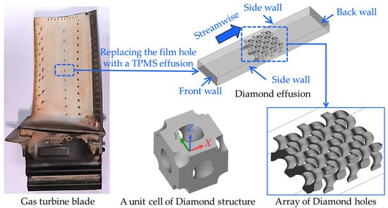
Figure 1.
Concept of the Diamond unit for gas turbine effusion cooling in this study.
All designs are based on a common external plate dimension with a width of 2.7 mm, a length of 11.7 mm, and a thickness of 0.9 mm. The configurations of this plate include a film-cooling hole, a micro-hole array, and a Diamond TPMS structure. The film-cooling model in Figure 2a is a single cylindrical hole with a diameter of 0.9 mm, tilted at a 30° angle. The micro-hole model in Figure 2b, inspired by designs of Min et al. [], consists of thirteen 0.3 mm diameter holes arranged in a staggered pattern, with streamwise and spanwise spacing of 0.3 mm, and each of these holes is also tilted at a 30° angle. The Diamond TPMS structure serves as an effusion cooling layer, generated with a unit cell size of 0.9 mm and a minimum hole size of approximately 0.3 mm, as shown in Figure 2c. The 3 × 3 × 1 array of the Diamond unit cells is embedded within the external plate. Although this network is periodic, the sides of the Diamond structure are asymmetric, and partition walls are incorporated to enhance structural integrity without compromising cooling efficiency [].
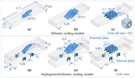
Figure 2.
Numerical models: (a) Film hole; (b) Micro-holes; (c) Diamond; (d) Imp-Film; (e) Imp-Micro, and (f) Imp-Diamond.
The porosity of the effusion plate is 4.0% for the film-hole model, 5.67% for the micro-hole model, and 5.43% for the Diamond model. The film hole model represents a baseline derived from a real gas turbine blade, while the micro-hole and Diamond TPMS models are designed with similar porosities. The comparison is conducted under a constant total pressure loss coefficient to provide a fair assessment of cooling performance under an equivalent pumping power requirement. This approach evaluates the influence of geometric configurations that can achieve superior heat transfer effectiveness for the same loss penalty.
The Diamond geometry is designed to be within the manufacturable limits of current powder bed fusion technology [,], mainly to demonstrate the inherent potential of the Diamond design. It is important to note that the internal topology, particularly of the Diamond geometry, creates a tortuous flow path that affects the discharge coefficient and effective flow area, leading to a flow distribution that differs from a simple area comparison. This is a key characteristic of TPMS-based effusion that significantly influences cooling performance, as documented in prior studies [,,].
For the double-wall configurations, the external plates from the effusion designs are integrated with an internal plate for jet impingement, as shown in Figure 2d–f. The jet holes are arranged in an in-line pattern with a spacing of 2.7 mm in both the streamwise and spanwise directions. This setting is justified by a prior study, which indicated that the jet hole arrangement has an insignificant effect on the local cooling effectiveness distribution []. The external plate configuration of all models is summarized in Table 1.

Table 1.
Details of the effusion cooling.
To study the influence of jet impingement on flow and heat transfer characteristics, the jet hole diameter is varied at Dj = 0.9 mm and Dj = 1.8 mm. The spacing between the internal and external plates is also investigated at Hj = 0.9 mm and Hj = 1.8 mm. The abbreviation ‘Imp-‘ indicates cases with jet impingement. ‘-L’ represents a large jet diameter, referring to a configuration with Dj = 1.8 mm and Hj = 0.9 mm. In contrast, ‘-H’ denotes a high jet-to-plate distance with Dj = 0.9 mm and Hj = 1.8 mm. The jet plate thickness is maintained at a low value of 0.9 mm to clearly observe the differences in flow and heat transfer distributions between the effusion and double-wall configurations []. While the pedestals and cross-flow could alter heat transfer and pressure loss, their influence is omitted to isolate the variables of primary interest. Table 2 shows the configurations of the jet impingement investigated in this study.
Table 2.
Configurations of the jet impingement.
2.2. Computational Domain and Boundary Conditions
The fluid flow and cooling effectiveness are analyzed using Ansys Fluent v. 2021R1, Ansys Inc., Canonsburg, PA, USA. The computational domains for the impingement/effusion configuration are shown in Figure 3. To reduce computational cost, the symmetry boundary condition is applied in the spanwise direction. The conjugate boundaries are defined at all solid–fluid interfaces, while all other surfaces are treated as adiabatic. It should be noted that the boundary conditions are selected to closely match the previous investigations [,,]. Both the mainstream and coolant are modeled as compressible ideal air. The mainstream inlet is defined by a uniform velocity (Vm) of 84 m/s and a temperature (Tm) of 672 K. The coolant inlet is specified by a mass flow rate and a temperature (Tc) of 320 K. The turbulence intensity of 5% and a hydraulic diameter corresponding to the inlet duct are specified. The outlet is set as a pressure outlet with a static pressure of 0 Pa. The solid domain is a nickel-based alloy, with material properties provided in the ref. []. For the case of the pure effusion, the internal plate is removed, and the same boundary conditions are implemented.
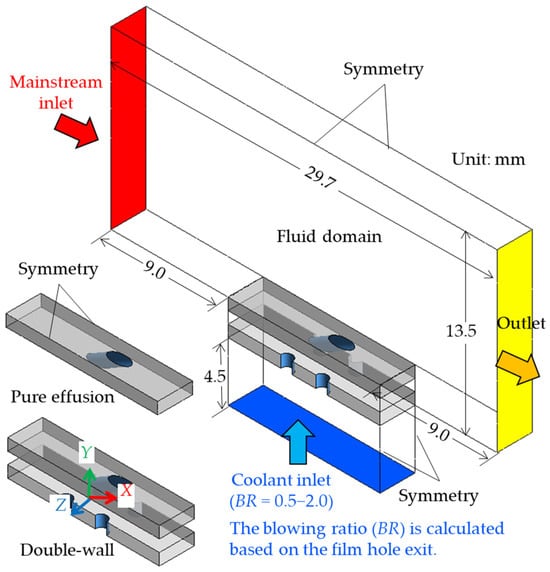
Figure 3.
Computational domain and boundary conditions.
A pressure-based solver is employed for all simulations. The pressure-velocity coupling is handled with the Coupled scheme and Rhie-Chow flux type. The second-order upwind scheme is used for the spatial discretization of all variables. The solution is considered converged when the residuals for the area-averaged mainstream inlet pressure, outlet velocity, and hot-side wall temperature of the effusion plate vary by less than 0.05% over 1000 iterations.
2.3. Parameter Definition
The blowing ratio (BR) is used to evaluate the coolant flow rate based on momentum interactions at the injection point in film cooling studies. Unlike the mass flux ratio, which generally uses the total system mass flow to evaluate coolant supply in transpiration cooling studies [], the BR is defined for a single injection hole using the local coolant velocity. It is calculated as:
where ρc and ρm are the densities of the coolant and mainstream, while Vc and Vm are the velocities of the coolant and mainstream. It should be noted that this definition of the BR is specific to the film hole exit used in this study. This calculated BR value is then used as a standardized label to denote the coolant supply level for all models, ensuring a direct comparison of thermal performance under equivalent coolant mass flow conditions. The BR is investigated within the range of 0.5 to 2.0.
To assess the internal cooling performance, the Nusselt number (Nu) is calculated for the cold-side surface of the external plate. The Nu is defined as:
where q and Twc denote the wall heat flux and the local wall temperature, measured on the cold-side surface of the external plate. kf is the thermal conductivity of the cooling air.
The overall cooling effectiveness (η) is used to evaluate the conjugate heat transfer performance on the hot-side surface of the external plate. It is defined as:
where Twm is the local wall temperature, acquired on the hot-side surface of the external plate.
The total pressure loss coefficient (ζtot) is evaluated to assess the aerodynamic penalty. This loss is primarily caused by the mixing of the coolant discharged with the mainstream and associated boundary layer phenomena, and is calculated as follows:
where ṁc and ṁm are the mass flow rates of the coolant and mainstream. ṁtot is the total mass flow rate, calculated by ṁtot = ṁc + ṁm. pc and pm are the pressures of the coolant and mainstream, measured at each inlet.
2.4. Mesh Independence and Numerical Scheme
The computational domain is discretized using poly-hexcore and prism elements generated with Fluent Meshing. As illustrated for the double-wall Diamond configuration in Figure 4, the mesh mainly consists of poly-hexcore cells in both the fluid and solid domains. To accurately resolve near-wall flow, dense prism layers are implemented at all no-slip surfaces, ensuring a y+ value of less than 1.0. For mesh generation efficiency, the boundary layers are initially extended to symmetry planes, and these are subsequently set to the correct symmetry condition before the simulation. The Shear Stress Transport (SST) k-ω turbulence model is selected for its demonstrated accuracy in predicting heat transfer, as it has shown good agreement with various experimental and numerical studies [,,].
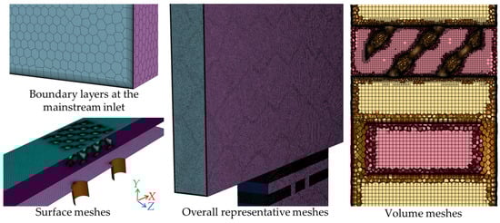
Figure 4.
An example of mesh systems of the Imp-Diamond configuration.
The mesh independence study is conducted on the most geometrically complex model, the Imp-Diamond configuration, at BR = 0.5. Three systematically refined meshes consisting of 7.65 × 10⁶, 8.56 × 10⁶, and 9.59 × 10⁶ elements are evaluated. As shown in Figure 5, the local temperature distributions at the mid-span of the hot-side surface are nearly identical across all three mesh resolutions. The results show a maximum temperature difference of only 0.16% between the meshes. Furthermore, the average grid convergence index (GCI) [] is calculated to be approximately 1.4%, confirming the independence of the mesh resolution. As the comparable computational time required by the 7.65 × 10⁶ and 8.56 × 10⁶ elements is similar, the mesh with 8.56 × 10⁶ elements is selected for the Imp-Diamond configuration to ensure the accuracy. Given that the Diamond model represents the most challenging topology, the same meshing strategy and settings are applied to the simpler micro-hole and film hole models. This approach ensures a consistent and validated standard of spatial discretization across all cases in this study.
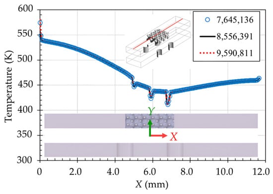
Figure 5.
Mesh independence check for the present numerical study.
2.5. Validation
The present numerical procedure, mesh, and turbulence model are validated against the infrared experimental data of Jung et al. [] at BR = 0.3. The reference experiment is an impingement/effusion cooling channel without pedestals, consisting of an effusion-cooled plate and an impinging jet plate, separated by a distance of one film hole diameter. The effusion and jet plates have thicknesses of 2.4 and 5.0 times the diameter of the film hole, respectively. All effusion holes are tilted by an angle of α = 35°. The experimental study considers two Biot numbers of 0.06 and 4.04. Figure 6 compares the numerical and experimental results of the spanwise-averaged cooling effectiveness on the hot-side surface of the effusion plate. The numerical results align closely with the experimental data. Although the minor fluctuations are present in the numerical results at the effusion hole exit, the overall agreement is acceptable, with mean deviations of 2.3% for the Biot number of 0.06 and 2.6% for the Biot number of 4.04. These results confirm the validity of the employed numerical procedure, mesh, and turbulence model, which can be applied to other proposed designs.
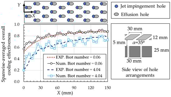
Figure 6.
Validations of the present numerical study with the infrared experimental data.
3. Results and Discussion
3.1. Internal Cooling Analysis
3.1.1. Impingement Flow and Temperature Contours
Figure 7 presents the streamlines in the plenum and temperature distributions on the effusion plate at BR = 1.5 for all designs. Each row corresponds to a different hole geometry group, while each column compares the effusion design with various jet impingement configurations. For the film hole in Figure 7a, the coolant in the plenum flows directly into the film hole, exhibiting a relatively limited lateral spread. The micro-hole and Diamond models distribute coolant evenly in their holes, lowering the temperature in the effusion plate.
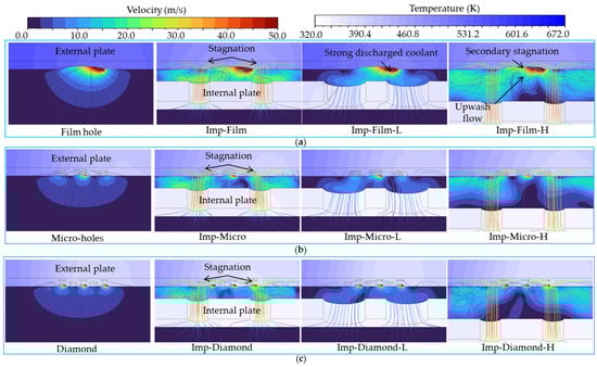
Figure 7.
Internal flow characteristics and temperature distribution on the cold-side surface at BR = 1.5: (a) Film hole models; (b) Micro-hole models, and (c) Diamond models.
The jet impingement enhances coolant mixing in the cavity due to the interaction between the jet, resulting in a more uniform temperature distribution throughout the cavity. However, the asymmetric impingement jet occurs in the film hole and micro-hole models, which is caused by preferential coolant ejection through upstream effusion holes that shifts the stagnation point. In the Diamond model, this effect is amplified by its internal topology, where interconnected networks, tortuous flow paths, and partition walls promote these asymmetric flow and temperature patterns.
For the jet case with a larger hole diameter (Dj = 1.8 mm, Hj = 0.9 mm), the flow and temperature results are similar to those without impingement, as the weaker and underdeveloped jets have a minor impact. Meanwhile, the case with a higher jet-to-plate distance (Dj = 0.9 mm, Hj = 1.8 mm) exhibits a more pronounced cooling effect. The Imp-Film-H model generates stronger impingement due to a well-developed jet in the stagnation region and creates a strong secondary stagnation in between [], thereby improving temperature uniformity.
In the group of the micro-holes in Figure 7b, and the Diamond in Figure 7c, the smaller effusion geometries weaken a strong discharged coolant by distributing the coolant through the holes, resulting in a more uniform temperature pattern. The jet impingement cases slightly improve the lateral spreading of the coolant, providing a more evenly distributed low-temperature region. However, the secondary stagnation is weakened since most of the coolant leaves the cavity through the small holes. In each group, similar to the film hole, the Imp-Micro-H and Imp-Diamond-H models exhibit the strongest interaction between impinging jets, generating the lowest temperature on the effusion plate.
3.1.2. Nusselt Number
Figure 8 shows the Nusselt number (Nu) contour on the cold-side surface at BR = 1.5. For the cases without the jet impingement in Figure 8a, the internal flow through the effusion holes induces distinct heat transfer patterns. The film hole model shows a high value only downstream, while the micro-hole generates a more distributed pattern due to its high hole densities. Moreover, the Diamond promotes a more uniform Nu distribution between its hole areas.
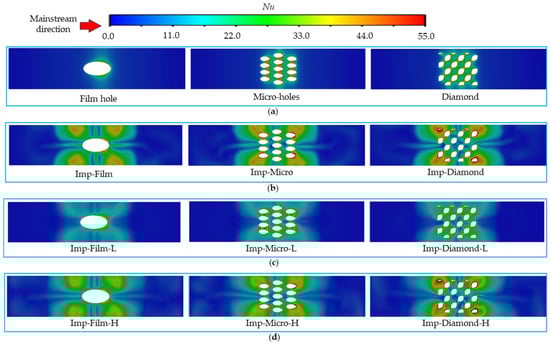
Figure 8.
Nusselt number distribution on the cold-side surface at BR = 1.5: (a) pure effusion; (b) integrated impingement with Dj = 0.9 mm and Hj = 0.9 mm; (c) integrated impingement with Dj = 1.8 mm and Hj = 0.9 mm, and (d) integrated impingement with Dj = 0.9 mm and Hj = 1.8 mm.
The jet impingement significantly enhances the Nusselt number, particularly within the stagnation region for configurations with a small jet diameter (Dj = 0.9 mm), as shown in Figure 8b,d. These cases exhibit a more intensified secondary peak in heat transfer compared to the larger diameter jet (Dj = 1.8 mm) in Figure 8c. The two secondary Nu peaks between the extraction holes in the film model are observed, while this effect is absent in the micro-hole and Diamond models due to the jet flowing through their effusion holes. This suggests that the benefits of the jet impingement are most pronounced for the film hole model, indicating that to fully exploit this benefit in the micro-hole and Diamond models, the effusion geometry should be carefully arranged.
Figure 9 plots the area-averaged Nu for all models within the range of BR = 0.5–2.0. The area-averaged Nu on the hot-side surface exhibits a monotonic increase with BR for all configurations, indicating that convective heat transfer is enhanced by higher coolant mass flow. The jet impingement substantially increases heat transfer. For each effusion geometry, the jet with a high jet-to-plate distance (Dj = 0.9 mm and Hj = 1.8 mm) exhibits the highest area-averaged Nu in all BR, which is most pronounced in the film hole model. However, the film hole still causes the lowest area-averaged Nu, while the micro-hole and Diamond show a similar increase. This can be attributed to their higher hole density, resulting in more distributed heat transfer enhancement.
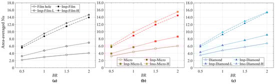
Figure 9.
Area-averaged Nusselt number within the BR = 0.5–2.0: (a) Film hole models; (b) Micro-hole models, and (c) Diamond models.
3.2. External Cooling Analysis
3.2.1. Flow Characteristics and Temperature Distributions
Figure 10 shows the flow streamlines, downstream velocity distributions, and temperature contours on the effusion plate for all models at BR = 1.5. Overall, the jet impingement has a minor influence on external flow characteristics, especially for the micro-holes and Diamond configurations. The film hole in Figure 10a causes a strong jet lift-off, which is commonly found at this high BR. This coolant detachment creates a low-pressure recirculation area downstream, leading to a significant mainstream ingestion. This hot gas, drawn downward behind this discharged coolant, causes a high temperature on the effusion plate. The jet impingement, particularly for the Imp-Film-H model, demonstrates an apparent mitigation by impinging high-momentum coolant onto the cold-side surface of the effusion plate, thereby lowering the temperature. Although the temperature on the effusion plate is reduced, the mainstream ingestion still causes non-uniform temperature distributions.
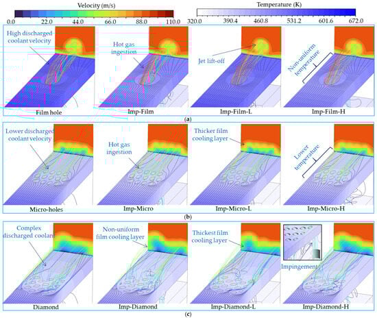
Figure 10.
External flow characteristics and temperature distribution on the effusion plate at BR = 1.5: (a) Film hole models; (b) Micro-hole models, and (c) Diamond models.
The jet lift-off is minimized in the micro-holes model due to the smaller diameter and lower momentum flow, as seen in Figure 10b. The flow interaction between the holes also helps reduce the strong discharged coolant. Despite the thicker coolant film layer than the film hole model, the mainstream ingestion along its sides results in incomplete surface coverage. Moreover, the jet impingement provides only a marginal improvement in downstream temperature, with no significant effect on the overall flow structure. The Diamond model demonstrates the most complex discharged coolant, where its topology alters the common flow structure found in cylindrical film holes. Before discharging, the coolant momentum is substantially decreased, which is the result of its pores. After ejection, the asymmetric external cooling in the Diamond model suppresses the dominant counter-rotating vortex pairs (CRVPs), observed in the film hole and micro-holes model. This disruption, despite non-uniform temperature distributions, promotes superior coolant coverage. Moreover, the mainstream ingestion, as found in the film hole and micro-hole models, is eliminated, resulting in a much lower temperature and a thicker film cooling layer. Although the jet impingement demonstrates a minimal influence on the temperature reduction in the Diamond configuration, it alters the external flow slightly, as the stagnation flow of the jet penetrates through the hole, as seen in the enlarged view of the Imp-Diamond-H model.
Figure 11 shows the temperature distributions on the mid-plane for all models at BR = 1.5. The film hole model, as seen in Figure 11a, exhibits a low-temperature region at the discharged region, which immediately transitions to a hot zone. This is a direct consequence of the jet lift-off at high BR. The jet impingement reduces the discharge of low-temperature coolant by exchanging heat at the cold-side wall with the stagnation flow, resulting in a lower-temperature downstream region compared to the case without jet impingement. Notably, the Imp-Film-H model shows the lowest temperature downstream among all film hole designs.
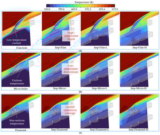
Figure 11.
Temperature distribution on the mid-plane at BR = 1.5: (a) Film hole models; (b) Micro-hole models, and (c) Diamond models.
The micro-hole and Diamond configurations achieve a much lower temperature than the film hole. The micro-hole in Figure 11b provides smooth and uniform temperature distributions inside the hole to the downstream regions. Moreover, the Diamond family in Figure 11c creates a non-uniform temperature distribution inside the hole. Despite its limited streamwise coverage in the far downstream region, the Diamond model contributes to a thicker coolant film due to its distributed effusion through numerous pores and an internal structure that lowers the discharged coolant velocity and improves its surface adhesion. Furthermore, for both configurations, the integrated jet impingement has only a minor influence on the temperature distributions, as the coolant flow is already distributed before it reaches the external wall.
3.2.2. Overall Cooling Effectiveness
The overall cooling effectiveness (η) distribution on the hot-side surface is plotted in Figure 12 to quantify the thermal protection and uniformity of each cooling design at BR = 1.5. Among non-impingement models in Figure 12a, the film hole model exhibits the lowest η and non-uniformity, primarily due to jet lift-off and mainstream ingestion. The micro-hole configuration achieves a higher η and a more uniform η distribution than the film hole, as the higher density of the discharged coolant holes generates a more continuous flow. The Diamond offers the highest η among the non-impingement configurations, although the pattern is non-uniform, a direct consequence of the asymmetric flow observed in Figure 10c. The topology of the Diamond hole, especially at the exit, promotes better attachment, offering superior thermal protection.
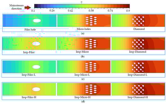
Figure 12.
Overall cooling effectiveness contour on the hot-side surface of the effusion plate at BR = 1.5: (a) pure effusion; (b) integrated impingement with Dj = 0.9 mm and Hj = 0.9 mm; (c) integrated impingement with Dj = 1.8 mm and Hj = 0.9 mm; and (d) integrated impingement with Dj = 0.9 mm and Hj = 1.8 mm.
For all effusion designs, the integrating jet impingement in the film hole model yields the most significant improvement in η, enhancing both its magnitude and uniformity. The micro-hole and Diamond models exhibit less sensitivity to the integration of the jet impingement, as their geometries are the dominant factor in the η improvement. Among the impingement designs, the Imp-Film-H, Imp-Micro-H, and Imp-Diamond-H models achieve the best performance, as shown in Figure 12d. This is attributed to their optimal jet-to-plate distance (Hj = 1.8 mm), which promotes a well-developed impinging jet and generates high turbulence in the stagnation region [].
Figure 13 presents the area-averaged η for all configurations within a range of BR = 0.5–2.0, evaluating the combined effect of internal and external cooling strategies on the overall thermal protection. The area-averaged η increases within the BR range of 0.5–1.5 and remains almost stable at BR = 2.0, attributed to jet lift-off being the dominant factor. The detachment of the discharged coolant leads to mainstream ingestion and subsequent degradation of the thermal protection.
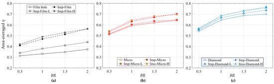
Figure 13.
Area-averaged overall cooling effectiveness within the BR = 0.5–2.0: (a) Film hole models; (b) Micro-hole models, and (c) Diamond models.
The film hole in Figure 13a exhibits the lowest area-averaged η, although the jet impingement significantly improves the cooling performance, especially at high BR. Meanwhile, the micro-hole model in Figure 13b demonstrates notably higher effectiveness within the studied BR. The Diamond configuration in Figure 13c achieves the highest area-averaged η, maintaining superior performance even at a high BR of 2.0, due to its topology effectively promoting the attachment of the discharged coolant. In all cases, the integration of jet impingement increases area-averaged η for all BRs and geometries.
Using the film hole model as the baseline, the improvement in area-averaged η of all cases within BR = 0.5–2.0 can be summarized in Table 3. A notable finding is the superior area-average η of the impingement case with the Dj = Hj = 0.9 mm at BR = 2.0 in all configurations. The low jet-to-plate distance intensifies internal cooling at high flow rates, resulting in high internal and external cooling. While the performance improvement is minor, it is recommended that the compact design is more advantageous, particularly in constrained areas of gas turbine blades, such as the narrow trailing edge, where higher jet-to-plate distance models cannot be accommodated.
Table 3.
Improvement in the area-averaged overall cooling effectiveness within BR = 0.5–2.0.
3.3. Overall Performance Analysis
3.3.1. Pressure Loss
To assess coolant pressure loss, the plenum pressure for all designs is plotted in Figure 14. Overall, the pressure loss increases with BR for all models, consistent with the higher momentum of the coolant flow. For a given hole design, integrating jet impingement increases the pressure loss compared to the pure effusion, as the impingement configuration generates additional flow resistance within the plenum, thereby requiring a higher pumping power. Among the impingement designs, the configuration with the small jet diameter and jet-to-plate distance (Dj = 0.9 mm, Hj = 0.9 mm) causes the highest pressure loss in all BR, due to its most restrictive internal flow path.
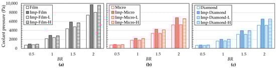
Figure 14.
Coolant pressure loss within the BR = 0.5–2.0: (a) Film hole models; (b) Micro-hole models, and (c) Diamond models.
In Figure 14a, the film hole design group exhibits the most pronounced pressure increases, particularly at BR = 2.0. The Imp-Film and Imp-Film-H models require substantially higher pressure, while the Imp-Film-L shows only a slight increase over the non-impingement case. Meanwhile, in Figure 14b, the micro-hole configuration exhibits a moderate pressure loss penalty, attributed to the lower momentum interaction within the cavity and a larger total discharge area. Surprisingly, the Diamond group in Figure 14c maintains the lowest plenum pressure loss despite having the most complex effusion topology. This finding suggests that for double-wall cooling designs, the plenum flow resistance is primarily determined by the internal jet interaction and the influence of hole geometries, rather than the discharge area of the effusion holes.
Figure 15 plots the total pressure loss coefficient (ζtot) for all cases at BR = 0.5–2.0. The increasing trend is similar to the plenum pressure loss, where the ζtot increases at higher BR for every hole group. However, this total loss is dominated by the mainstream-coolant mixing at a higher BR over the influence of the jet impingement designs. The micro-hole group exhibits the lowest ζtot value, particularly at BR = 1.5–2.0, whereas the Diamond configuration generates the highest total loss values. This result is consistent with the thicker film layer, which creates stronger momentum exchange with the mainstream and discharged coolant. The impingement designs, especially the Imp-Film-L, in each group induce a minor increase in ζtot values, compared to the pure effusion.
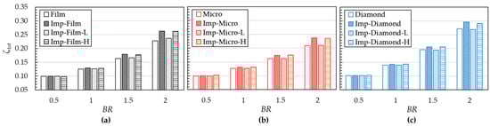
Figure 15.
Total pressure loss coefficient within the BR = 0.5–2.0: (a) Film hole models; (b) Micro-hole models, and (c) Diamond models.
3.3.2. Performance Evaluation
Table 4 plots the area-averaged η value at fixed ζtot for all cases. The results of the film hole model without the jet impingement are used as the benchmark for comparison. By maintaining a constant ζtot value, the influence of the geometries and the addition of the jet on cooling performance can be clearly isolated. This comparison at identical total pressure loss directly correlates the cooling performance to the required pumping power, whereas normalization by mainstream loss only would conflate the cooling performance with aerodynamic blockage.
Table 4.
Improvement in the area-averaged overall cooling effectiveness at a fixed total loss.
The results showed that in almost all design groups, the incorporation of the impinging jet yields a moderate improvement of approximately 10% in the area-averaged η. However, a significant enhancement of about 30% is observed for the film hole family when the jet impingement is integrated as double-wall cooling. Among all tested configurations, the Imp-Diamond-H design achieves the highest performance, resulting in a 101% increase in area-averaged η compared to the film hole model. This confirms that the combination of the optimized hole topology with the proper jet impingement design provides the highest cooling effectiveness under equal loss conditions.
3.4. Thermal-Mechanical Analysis
3.4.1. Static Structural Simulation Approach
In this section, the thermal-mechanical performance of the double-wall models (Dj = Hj = 0.9 mm) at BR = 2.0 is studied using Ansys Static Structural, based on the finite element method (FEM). Additionally, only the external plate is considered, as shown in Figure 16a, since it is primarily exposed to the high-temperature mainstream, allowing for clear observation of changes in thermal stress and displacement. Then, all models are meshed using the same cell size of 0.03 mm; hence, the number of elements falls within the range of 5.8 × 10⁶ to 7.2 × 10⁶. Examples of the mesh system for static structural analysis are demonstrated in Figure 16b.
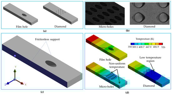
Figure 16.
Static structural analysis procedure: (a) imported external plate geometry; (b) model meshing; (c) assigned constraint, and (d) imported body temperature.
In order to replicate a typical double-wall cooling unit, the left and right sides of the external plate are subjected to frictionless support conditions, as depicted in Figure 16c [,]. These conditions prevent the plates from deforming along the normal direction (Z-axis). The symmetry boundary conditions are also applied to the plate sides, as in the Fluent settings. Lastly, the body temperature field obtained from the Fluent results is imported as the thermal load to the Ansys Static Structural, as shown in Figure 16d. The reference temperature is established at 295.15 K. The remaining walls are treated as free boundary conditions, allowing for free deformation due to thermal expansion. The temperature-dependent properties of the nickel-based superalloy material used in the solid domain of this study can be observed in ref. [].
The temperature variation near the mainstream inlet, as illustrated in Figure 16d, is due to differing backflow regimes. The strong discharge of coolant in the film hole model induces significant upstream flow separation and recirculation, causing the hotter fluid to back towards the inlet. Furthermore, the distributed effusion of the micro-hole and Diamond models is less disruptive to the boundary layer, resulting in a cooler inlet region. This is a typical result of the conjugate heat transfer solution, where the solid temperature influences this flow field.
Among all cases, the Diamond model exhibits the largest regions of low temperature on the effusion plate because this topology forms the thickest coolant. Furthermore, the temperature on the hot-side surface of the effusion wall is distributed more uniformly compared to the other models. Moreover, the film hole model shows the highest temperature upstream and low temperature near the hole area [,], while the micro-hole model causes noticeable non-uniform temperature distributions. These results are due to the internal and external flow characteristics, which influence the thermal stress and displacement variations.
3.4.2. Thermal Stress Analysis
The equivalent von-Mises stress is employed to illustrate the thermal stress resulting from the thermal load in the double-wall configuration at BR = 2.0, as shown in Figure 17. For the film hole in Figure 17a, the areas of high thermal stress are unevenly distributed around the hole. The critical stress points are located at the acute wedge-vertex of film holes, which aligns with the findings of previous studies [,,,]. Similarly, for the micro-hole model in Figure 17b, the thermal stress distribution resembles that in the film hole. However, due to the greater number of holes, the stress is lower on the acute wedge-vertex of the holes; still, the stress is non-uniformly distributed, especially between holes and downstream. This result can also be attributed to the uneven temperature pattern.
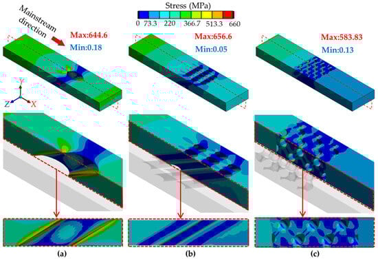
Figure 17.
Equivalent von-Mises stress distributions on the external plate at BR = 2.0: (a) Film hole; (b) Micro-holes, and (c) Diamond.
On the other hand, the Diamond model demonstrates a superior thermo-structural performance, as evidenced in Figure 17c. Its continuous and interconnected network distributes heat more effectively, creating smoother temperature contours. The absence of sharp corners further eliminates local stress concentrations. Consequently, the Diamond model exhibits a more uniform stress distribution on the hot-side surface, which directly mitigates the stress concentrations that drive fatigue failure. This design achieved a lower average thermal stress, with reductions of 44.7% and 16.9% compared to the film-hole and micro-hole models, respectively.
3.4.3. Displacement Analysis
Figure 18 illustrates the total deformation for all double-wall models at BR = 2.0. It is observed that the deformation gradually decreases in the direction of the hot gas, with a slight increase occurring downstream of the film hole model, as seen in Figure 18a. The micro-hole model in Figure 18b also causes a non-uniform displacement downstream. These two models exhibit similar displacement patterns at the end of the external plate due to the jet lift-off, reducing the temperature difference between the hot gas and the hot-side surface of the external plate. For the Diamond in Figure 18c, the displacement contour uniformly decreases along the mainstream direction since the thick coolant fully covers the plate from the high-temperature mainstream. Here, the average displacement in the micro-hole and Diamond models is 32.7% and 35.6% lower than in the film hole. Moreover, the maximum displacement value in the Diamond model is lower than that of the film hole and micro-hole models. The Diamond shows the lowest maximum displacement value by 25% compared to the film hole.
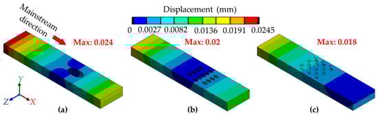
Figure 18.
Displacement contours on the external plate at BR = 2.0: (a) Film hole; (b) Micro-holes, and (c) Diamond.
The directional deformations at BR = 2.0 can be observed in Figure 19. Only the X- and Y-directional deformations are shown since there is no deformation along the Z-axis because of the frictionless support boundary. The positive value indicates the material expansion along the X- and Y-directions, whereas the negative value signifies the material contraction in the opposite direction. All models significantly deform in the X-axis, where the high-temperature mainstream flows along this direction, indicating that the thermal load stretches the external plate. The film hole deforms the most upstream, followed by the Diamond and micro-hole models. Furthermore, the deformation in the Y-axis for all models can also be observed. The film hole and micro-hole models exhibit different patterns from the Diamond designs. The downstream film hole and micro-hole models are bent along the Y-axis, while the Diamond models remain unchanged. This result is due to the lower middle and downstream temperatures in the Diamond effusion plate, as seen in Figure 19f.
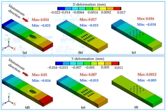
Figure 19.
Contours of directional deformation on the external plate at BR = 2.0. Upper row (X-direction deformation): (a) Film hole, (b) Micro-holes, (c) Diamond. Lower row (Y-direction deformation): (d) Film hole, (e) Micro-holes, (f) Diamond.
4. Conclusions
In this study, the Diamond TPMS network is employed for effusion cooling, compared with the conventional film hole and micro-hole models. All effusion geometries are also studied in a double-wall system, incorporating various jet impingement configurations. The flow field, pressure loss, and overall cooling effectiveness of all configurations are investigated at BR values ranging from 0.5 to 2.0, using conjugate heat transfer simulations. Moreover, the thermal stress and displacement are analyzed. The main findings can be concluded as follows:
- (1)
- The Diamond TPMS design generates a different flow pattern from the cylindrical film and micro-hole models. It suppresses jet lift-off and eliminates counter-rotating vortex pairs, resulting in a thicker coolant film that provides more complete coverage on the effusion plate. The Diamond structure, due to its complex internal topology, achieves higher cooling effectiveness by releasing coolant that attaches to the wall and ensuring a more uniform temperature distribution on the effusion plate.
- (2)
- Integrating jet impingement as a double-wall cooling system generally increases the area-averaged Nusselt number. The most beneficial impact of the jet is observed in the film hole model due to a more pronounced secondary peak in heat transfer, and this peak corresponds to the region of high heat transfer in the wall jet formed after the impingement stagnation point. For the micro-hole and Diamond models, the internal surface areas are large, allowing the jet flow to penetrate to the hole. Therefore, the jet impingement has a smaller influence on the temperature distribution of the external plate. In all designs, the jet configuration with Dj = 0.9 mm and Hj = 1.8 mm shows the highest area-averaged Nusselt number.
- (3)
- While overall cooling effectiveness and pressure loss increase with BR for all models, the Diamond designs outperform the others. The cooling effectiveness and pressure loss are further increased when jet impingement is incorporated. At an equal total pressure loss, the Diamond with the jet impingement (Dj = 0.9 mm, Hj = 1.8 mm) provides a 101% higher cooling effectiveness than the pure film hole configuration.
- (4)
- The Diamond model demonstrates a 44.7% reduction in thermal stress compared to the film hole model, with a more uniform stress and displacement distribution on the effusion plate. This combination of the higher cooling effectiveness and lower thermal stress suggests that the Diamond TPMS effusion is the most effective thermo-mechanical design in this study, presenting a promising high-performance cooling solution for advanced gas turbines.
Although the Diamond effusion demonstrates various advantages, the benefits could be counterbalanced by higher manufacturing complexity, surface roughness, potential clogging, and the limitation of this study, which used cylindrical film holes as a baseline. Future work should therefore focus on experimental validation, a direct performance comparison with advanced shaped film holes, and optimized hole configurations to establish a more comprehensive benchmark for this promising technology.
Author Contributions
Conceptualization, K.Y. and Y.R.; methodology, K.Y., C.X. and Y.C.; software, K.Y.; validation, K.Y., C.X. and Y.C.; formal analysis, K.Y. and Y.C.; investigation, K.Y., C.X. and Y.C.; resources, K.Y. and Y.R.; data curation, K.Y., C.X. and Y.C.; writing—original draft preparation, K.Y.; writing—review and editing, K.Y., C.X., Y.R. and Y.C.; visualization, K.Y., C.X. and Y.C.; supervision, Y.R.; project administration, Y.R.; funding acquisition, K.Y. and Y.R. All authors have read and agreed to the published version of the manuscript.
Funding
This work was supported by grants from the National Natural Science Foundation of China (Nos. 11972230, W2433143), the National Science and Technology Major Project of China (No. 2017-III-0009-0035), and the Science and Technology Commission of Shanghai Municipality (No. 24110712700).
Data Availability Statement
The original contributions presented in this study are included in the article. Further inquiries can be directed to the corresponding author.
Acknowledgments
Yu Rao gratefully acknowledges support from the Shandong Provincial Industrial Leading Talents Project.
Conflicts of Interest
The authors declare no conflicts of interest.
Nomenclature
| BR | Blowing ratio (−) |
| Dj | Diameter of the jet hole (m) |
| Vc, Vm | Velocity of the coolant and mainstream (m/s) |
| Tc, Tm | Temperature of the coolant and hot gas (K) |
| Twc, Twm | Temperature of the cold- and hot-side surfaces of the external plate (m) |
| Nu | Nusselt number on the cold-side surface of the external plate (−) |
| q | Wall heat flux on the cold-side surface of the external plate (W/m2) |
| kf | Thermal conductivity of the cooling air (W/m·K) |
| ζtot | Total pressure loss coefficient (−) |
| Mass flow rate of the coolant and hot gas (kg/s) | |
| Total mass flow rate (kg/s) | |
| pc, pm | Inlet pressure of the coolant and hot gas (Pa) |
| ph, out | Outlet pressure of the hot gas (Pa) |
| y+ | Dimensionless wall distance (−) |
References
- Araki, M.; Masada, J.; Hada, S.; Ito, E.; Tsukagoshi, K. Development of Mitsubishi 1600 °C Class J-Type Gas Turbine. In Proceedings of the ASME 2011 Power Conference, Denver, CO, USA, 12–14 July 2011; ASMEDC: New York, NY, USA, 2011; Volume 1, pp. 635–641. [Google Scholar]
- Yeranee, K.; Rao, Y. A Review of Recent Studies on Rotating Internal Cooling for Gas Turbine Blades. Chinese J. Aeronaut. 2021, 34, 85–113. [Google Scholar] [CrossRef]
- Lu, Y.; Zhang, M.; Chen, Y.; Ju, J.; Chen, F.; Bai, K.; Wang, X. A Newly Developed Multi-Strategy Optimization Algorithm Framework Based on the Adaptive Switching Approach Coupled with Grey Wolf Optimizer. Knowl. Inf. Syst. 2025, 67, 5571–5617. [Google Scholar] [CrossRef]
- Wang, W.; Yan, Y.; Zhou, Y.; Cui, J. Review of Advanced Effusive Cooling for Gas Turbine Blades. Energies 2022, 15, 8568. [Google Scholar] [CrossRef]
- Mi, Q.; Yi, S.H.; Gang, D.D.; Lu, X.G.; Liu, X.L. Research Progress of Transpiration Cooling for Aircraft Thermal Protection. Appl. Therm. Eng. 2024, 236, 121360. [Google Scholar] [CrossRef]
- Reimer, T.; Kuhn, M.; Gülhan, A.; Esser, B.; Sippel, M.; van Foreest, A. Transpiration Cooling Tests of Porous CMC in Hypersonic Flow. In Proceedings of the 17th AIAA International Space Planes and Hypersonic Systems and Technologies Conference, San Francisco, CA, USA, 11–14 April 2011; American Institute of Aeronautics and Astronautics: Reston, VA, USA, 2011; pp. 1–13. [Google Scholar]
- Langener, T.; von Wolfersdorf, J.; Steelant, J. Experimental Investigations on Transpiration Cooling for Scramjet Applications Using Different Coolants. AIAA J. 2011, 49, 1409–1419. [Google Scholar] [CrossRef]
- Kumar, C.S.; Pattamatta, A. Assessment of Heat Transfer Enhancement Using Metallic Porous Foam Configurations in Laminar Slot Jet Impingement: An Experimental Study. J. Heat Transfer 2018, 140, 022202. [Google Scholar] [CrossRef]
- Liu, Y.Q.; Jiang, P.X.; Xiong, Y.B.; Wang, Y.P. Experimental and Numerical Investigation of Transpiration Cooling for Sintered Porous Flat Plates. Appl. Therm. Eng. 2013, 50, 997–1007. [Google Scholar] [CrossRef]
- Xu, G.; Liu, Y.; Luo, X.; Ma, J.; Li, H. Experimental Investigation of Transpiration Cooling for Sintered Woven Wire Mesh Structures. Int. J. Heat Mass Transf. 2015, 91, 898–907. [Google Scholar] [CrossRef]
- Hinse, M.; Yildiz, K.; Richer, P.; Jodoin, B.; Bourmand, M.; Yun, S.; Hong, Z. Numerical and Experimental Studies of Transpiration Cooling Film Effectiveness over Porous Materials. J. Thermophys. Heat Transf. 2022, 36, 803–817. [Google Scholar] [CrossRef]
- Huang, Z.; Xiong, Y.B.; Liu, Y.Q.; Jiang, P.X.; Zhu, Y.H. Experimental Investigation of Full-Coverage Effusion Cooling through Perforated Flat Plates. Appl. Therm. Eng. 2015, 76, 76–85. [Google Scholar] [CrossRef]
- Wambersie, A.; Wong, H.; Ireland, P.; Mayo, I. Experiments of Transpiration Cooling Inspired Panel Cooling on a Turbine Blade Yielding Film Effectiveness Levels over 95%. Int. J. Turbomach. Propuls. Power 2021, 6, 16. [Google Scholar] [CrossRef]
- Yeranee, K.; Rao, Y. A Review of Recent Research on Flow and Heat Transfer Analysis in Additively Manufactured Transpiration Cooling for Gas Turbines. Energies 2025, 18, 3282. [Google Scholar] [CrossRef]
- Min, Z.; Parbat, S.N.; Yang, L.; Chyu, M.K. Thermal-Fluid and Mechanical Investigations of Additively Manufactured Geometries for Transpiration Cooling. In Proceedings of the Volume 5B: Heat Transfer, Phoenix, AZ, USA, 17–21 June 2019; American Society of Mechanical Engineers: New York, NY, USA, 2019; Volume 5B-2019, pp. 1–13. [Google Scholar]
- Huang, G.; Min, Z.; Yang, L.; Jiang, P.-X.; Chyu, M. Transpiration Cooling for Additive Manufactured Porous Plates with Partition Walls. Int. J. Heat Mass Transf. 2018, 124, 1076–1087. [Google Scholar] [CrossRef]
- Stimpson, C.K.; Snyder, J.C.; Thole, K.A.; Mongillo, D. Roughness Effects on Flow and Heat Transfer for Additively Manufactured Channels. J. Turbomach. 2016, 138, 051008. [Google Scholar] [CrossRef]
- Kim, M.; Shin, D.H.; Kim, J.S.; Lee, B.J.; Lee, J. Experimental Investigation of Effusion and Transpiration Air Cooling for Single Turbine Blade. Appl. Therm. Eng. 2021, 182, 116156. [Google Scholar] [CrossRef]
- Kim, M.; Shin, D.H.; Lee, B.J.; Lee, J. Experimental and Numerical Investigation of Micro-Scale Effusion and Transpiration Air Cooling on Cascaded Turbine Blades. Case Stud. Therm. Eng. 2022, 32, 101892. [Google Scholar] [CrossRef]
- Poupinha, C.; Kozlowska, S.; Lluch, J.S.; Altimare, D.; Kinell, M. Experimental Study on Transpiration Cooling through Additively Manufactured Porous Structures. Int. J. Heat Mass Transf. 2024, 227, 125532. [Google Scholar] [CrossRef]
- Xu, R.; Cheng, Z.; Jiang, P. Fundamentals and Recent Progress of Additive Manufacturing-Assisted Porous Materials on Transpiration Cooling. J. Glob. Power Propuls. Soc. 2023, 2023, 19–48. [Google Scholar] [CrossRef] [PubMed]
- Min, Z.; Huang, G.; Parbat, S.N.; Yang, L.; Chyu, M.K. Experimental Investigation on Additively Manufactured Transpiration and Film Cooling Structures. J. Turbomach. 2019, 141, 031009. [Google Scholar] [CrossRef]
- Fier, N.D.; Bogard, D.G. Additively Manufactured Porous Geometries for Hybrid Turbine Cooling. In Proceedings of the Volume 5A: Heat Transfer—Combustors, Virtual, 7–11 June 2021; Film Cooling. American Society of Mechanical Engineers: New York, NY, USA, 2021; Volume 5A-2021, pp. 1–10. [Google Scholar]
- Broumand, M.; Son, J.; Pyo, Y.; Yun, S.; Hong, Z. TPMS-Based Transpiration Cooling for Film Cooling Enhancement. Int. J. Heat Mass Transf. 2024, 231, 125824. [Google Scholar] [CrossRef]
- Yeranee, K.; Zuo, Q.; Rao, Y.; Cheng, Y. Conjugate Heat Transfer Simulations Of Vortex Chamber With Diamond-Type Tpms Effusion For Gas Turbine Blade Leading Edge Cooling. In Proceedings of the Global Power and Propulsion Society, Shanghai, China, 4–6 September 2025. [Google Scholar]
- Kim, K.M.; Song, J.; Park, J.S.; Lee, S.; Cho, H.H. Material Design of a Film Cooling System Using Experimental Heat Transfer Data. Int. J. Heat Mass Transf. 2012, 55, 6278–6284. [Google Scholar] [CrossRef]
- Kim, K.M.; Moon, H.; Park, J.S.; Cho, H.H. Optimal Design of Impinging Jets in an Impingement/Effusion Cooling System. Energy 2014, 66, 839–848. [Google Scholar] [CrossRef]
- Wang, S.; Li, X.; Ren, J. Film Cooling and Stress Concentration Properties of the Backward-Diffusion Elliptical Hole. Appl. Therm. Eng. 2024, 244, 122713. [Google Scholar] [CrossRef]
- Li, W.; Lu, X.; Li, X.; Ren, J.; Jiang, H. On Improving Full-Coverage Effusion Cooling Efficiency by Varying Cooling Arrangements and Wall Thickness in Double Wall Cooling Application. J. Heat Transfer 2019, 141, 042201. [Google Scholar] [CrossRef]
- Liu, R.; Li, H.; You, R.; Huang, Y.; Tao, Z. Conjugate Heat Transfer Study of Various Cooling Structures and Sensitivity Analysis of Overall Cooling Effectiveness. Sci. Rep. 2022, 12, 19271. [Google Scholar] [CrossRef]
- Yeranee, K.; Xu, C.; Rao, Y.; Cheng, Y.; Zuo, Q.; Zhang, G. Conjugate Heat Transfer and Flow Analysis of Double-Wall Cooling with Printable Gyroid-Type TPMS-Based Effusion. Aerospace 2025, 12, 854. [Google Scholar] [CrossRef]
- Son, J.; Pyo, Y.; Richer, P.; Jodoin, B.; Hong, Z. Impact of TPMS Structure Unit Cell Size on Transpiration Cooling. In Proceedings of the AIAA Science and Technology Forum and Exposition, AIAA SciTech Forum 2025, Orlando, FL, USA, 6–10 January 2025; American Institute of Aeronautics and Astronautics: Reston, VA, USA, 2025; pp. 1–17. [Google Scholar]
- Yeranee, K.; Rao, Y.; Xu, C.; Xie, J.; Zhang, Y. Conjugate Heat Transfer and Fluid Flow Analysis on Printable Double-Wall Effusion Cooling with Internal Topology-Optimized TPMS Structures. Therm. Sci. Eng. Prog. 2024, 55, 102939. [Google Scholar] [CrossRef]
- Skamniotis, C.; Courtis, M.; Cocks, A.C.F. Multiscale Analysis of Thermomechanical Stresses in Double Wall Transpiration Cooling Systems for Gas Turbine Blades. Int. J. Mech. Sci. 2021, 207, 106657. [Google Scholar] [CrossRef]
- Son, J.; Broumand, M.; Pyo, Y.; Richer, P.; Jodoin, B.; Hong, Z. Effects of Lattice Orientation Angle on TPMS-Based Transpiration Cooling. In Proceedings of the Volume 13: Heat Transfer: General Interest/Additive Manufacturing Impacts on Heat Transfer, London, UK, 24–28 June 2024; Wind Energy. American Society of Mechanical Engineers: New York, NY, USA, 2024; Volume 13, pp. 1–13. [Google Scholar]
- Nakamata, C.; Mimura, F.; Matsushita, M.; Yamane, T.; Fukuyama, Y.; Yoshida, T. Local Cooling Effectiveness Distribution of an Integrated Impingement and Pin Fin Cooling Configuration. In Proceedings of the Volume 4: Turbo Expo 2007, Parts A and B, Montreal, QC, Canada, 14–17 May 2007; ASMEDC: New York, NY, USA, 2007; Volume 4 PART A, pp. 23–34. [Google Scholar]
- Shaikh, H.I.; Siddapureddy, S.; Prabhu, S.V. Effect of Jet Plate Thickness on the Local Heat Transfer Coefficient with Multiple Air Jet Impingement. Appl. Therm. Eng. 2023, 229, 120517. [Google Scholar] [CrossRef]
- Li, H.; Xie, F.; Wang, Y.; Wang, C.; Yan, Y.; Cui, J. Numerical Investigation on the Cooling Effectiveness and Pressure Loss of a Novel Laminated Cooling Configuration With Cellular Partition. J. Therm. Sci. Eng. Appl. 2023, 15, 011015. [Google Scholar] [CrossRef]
- Celik, I.B.; Ghia, U.; Roache, P.J.; Freitas, C.J.; Coleman, H.; Raad, P.E. Procedure for Estimation and Reporting of Uncertainty Due to Discretization in CFD Applications. ASME J. Fluids Eng. 2008, 130, 078001. [Google Scholar] [CrossRef]
- Jung, E.Y.; Chung, H.; Choi, S.M.; Woo, T.; Cho, H.H. Conjugate Heat Transfer on Full-Coverage Film Cooling with Array Jet Impingements with Various Biot Numbers. Exp. Therm. Fluid Sci. 2017, 83, 1–8. [Google Scholar] [CrossRef]
- Wae-hayee, M.; Yeranee, K.; Piya, I.; Rao, Y.; Nuntadusit, C. Heat Transfer Correlation of Impinging Jet Array from Pipe Nozzle under Fully Developed Flow. Appl. Therm. Eng. 2019, 154, 37–45. [Google Scholar] [CrossRef]
Disclaimer/Publisher’s Note: The statements, opinions and data contained in all publications are solely those of the individual author(s) and contributor(s) and not of MDPI and/or the editor(s). MDPI and/or the editor(s) disclaim responsibility for any injury to people or property resulting from any ideas, methods, instructions or products referred to in the content. |
© 2025 by the authors. Licensee MDPI, Basel, Switzerland. This article is an open access article distributed under the terms and conditions of the Creative Commons Attribution (CC BY) license (https://creativecommons.org/licenses/by/4.0/).