Abstract
The ever-growing scale of offshore wind power integration has led coastal provincial power grids to face the common issue of insufficient AC grid structure capacity. An effective solution involves constructing an offshore–onshore mono–bipolar hybrid high voltage DC (HVDC) system by integrating an offshore wind monopolar HVDC with an onshore embedded bipolar HVDC. Firstly, the limitations of existing AC structures in coastal grids when undertaking offshore wind power integration are analyzed through N-1 security verification, and the applicability of conventional power evacuation approaches is assessed from both theoretical and practical engineering standpoints. Subsequently, an offshore–onshore mono–bipolar hybrid HVDC system is proposed. Meanwhile, based on operational requirements and the analysis of the structural features, a coordinated control strategy for the hybrid HVDC system under both symmetric and asymmetric operation modes is designed. Finally, a simulation model is built on the PSCAD/EMTDC platform to verify the feasibility of the hybrid HVDC system control strategy in the coastal power grid and the effectiveness of the system to improve the wind power consumption capacity of the coastal power grid.
1. Introduction
In recent decades, the global transition towards a sustainable and carbon-neutral future has positioned offshore wind energy at the forefront of renewable energy development. Unlike its onshore counterpart, offshore wind offers access to stronger, more consistent wind resources, resulting in significantly higher capacity factors and energy yield. According to the Global Wind Energy Council, the industry added 8 GW of new capacity in 2024, bringing the global total to 83 GW [1]. Driven by the urgent need to mitigate climate change and enhance energy security and sustainability, this growth momentum is expected to continue over the coming decade. In China, the grid-connected capacity of offshore wind power is projected to reach 150 GW by 2030.
High-Voltage Direct Current (HVDC) transmission has matured into a competitive solution for large-scale power transmission over long distances, as demonstrated by operational projects like the DolWin6 link in Germany [2], the Rudong Offshore Wind Connector in China [3], and the HVDC MONITA between Italy and Montenegro [4,5]. These projects underscore HVDC’s ability to effectively overcome the limitations of long-distance and cross-water power transmission, while addressing the inherent limitations of traditional AC power transmission. Nevertheless, a critical challenge remains after transmitting offshore wind power via HVDC to coastal grids. The geographical challenge posed by the long distance between load centers and coastal grids forces the wind power to be funneled through limited AC transmission lines, intensifying the overload risks of coastal grids. This issue has been recognized and discussed in several studies related to offshore wind integration [6,7,8,9,10]. Characterized by a significant geographical mismatch between generation and load, the Jiangsu power grid exemplifies this issue. Offshore wind power integrated via HVDC in northern Jiangsu must still be transmitted to the load centers in the south. Consequently, the onshore AC corridors are tasked with carrying this substantial surplus wind power, leading to pronounced heavy-load and overload risks that demand further technical solutions [11,12].
Extensive research has been conducted on methods to enhance grid hosting capacity under large-scale renewable integration [13,14,15,16,17]. Among these solutions, embedded DC has been implemented in practical projects such as the Caprivi Link in Namibia and the Wufengshan DC in China, demonstrating its effectiveness as a validated solution [18,19]. Unlike traditional long-distance HVDC, embedded DC situates its converter stations within the same AC grid, significantly improving the grid’s transmission capacity, controllability, and flexibility. Substantial studies have focused on its planning, operation control, and fault ride-through capabilities [11,19,20,21].
Regarding converter topologies for embedded DC, the majority of established research utilize thyristor-based Line-Commutated Converters (LCC) [11,19,21,22]. Meanwhile, several studies have investigated embedded DC systems using Insulated Gate Bipolar Transistor (IGBT) based Modular Multilevel Converters (MMC) [20]. Reference [23] categorizes these into Current Source Converters (CSC) and Voltage Source Converters (VSC), providing a detailed discussion of their respective technical characteristics and application scopes. VSC-HVDC demonstrates superior performance in weak AC grids, while offering superior power control flexibility. As such, it exhibits better suitability for offshore wind power integration and the coastal grids with low Short-Circuit Ratios (SCR).
However, existing research on embedded DC is predominantly confined to purely onshore grid applications. A promising pathway to better leverage embedded DC for alleviating offshore wind power surpluses is to integrate it into coastal power grids. Furthermore, consolidating the offshore wind transmission HVDC with the onshore embedded DC system can enhance the overall integration, economic viability, and coordinated control performance of the HVDC system. To this end, this paper proposes a novel hybrid mono–bipolar HVDC system while establishing a foundational framework for its steady-state operation and control strategies, thereby paving the way for future in-depth transient analysis. The main contributions of this paper are as follows:
- (1)
- A novel hybrid HVDC system is proposed, integrating an onshore symmetric bipolar HVDC with an offshore symmetric monopolar HVDC. This topology eliminates redundant converter stations required in a conventional independent HVDC scheme, leading to superior economic efficiency and enhanced coordinated control capabilities.
- (2)
- A comprehensive scheme of operation modes and control strategies is designed, tailored to the functional requirements and structural characteristics of the proposed hybrid DC system. The system’s two distinct operating modes, symmetric and asymmetric, provide greater adaptability and improved operational reliability.
The remainder of this paper is organized as follows. Section 2 takes the Jiangsu power grid as a typical case to analyze the impacts of large-scale offshore wind integration on coastal grids and outlines the rationale for proposing a hybrid mono–bipolar HVDC system. In Section 3, the detailed topology of the hybrid HVDC system is presented, which is designed to simultaneously transmit offshore wind power and alleviate coastal grid power flow, while a techno-economic analysis is conducted to highlight its advantages over conventional solutions. Based on the system structure, the operation modes and corresponding control strategies of the hybrid HVDC system are proposed in Section 4. Section 5 validates the effectiveness of the proposed operation modes and strategies via simulations performed on PSCAD/EMTDC. Conclusions are drawn in Section 6.
2. Discussion on the Construction Background of Hybrid Mono–Bipolar HVDC System
2.1. The Impacts of Offshore Wind Farms Integration on Coastal Power Grids
The provincial power grid of Jiangsu, one of the coastal provincial power grids in eastern China, features a relatively large-scale integration of offshore wind power. It is projected that by 2030, the total installed capacity of wind power in Jiangsu will reach 50 GW, accounting for 17.2% of the total installed capacity, of which offshore wind power will amount to 30 GW [11]. By 2050, it is expected that 60-GW-scale offshore wind power will be integrated. This makes the grid of Jiangsu a typical coastal provincial power grid case significantly affected by offshore wind power integration.
Geographically, Jiangsu Province is bisected by the Yangtze River, forming distinct northern and southern power grids. The northern power grid is characterized by a concentrated generation capacity but bears a relatively low local load, whereas the southern power grid is a major load center with less local generation. This structural imbalance necessitates the transmission of surplus power from the northern power grid to the southern power grid via cross-river transmission corridors. Complicating this situation, offshore wind farms (OWFs) of Jiangsu Province are, due to geographical constraints, primarily integrated into the northern power grid. The large-scale injection of wind power will thus exacerbate the existing power flow imbalance, posing more severe challenges to the coastal power grid in northern Jiangsu, particularly in terms of transmission congestion under high wind generation conditions.
As shown in Figure 1, Area F, located along the coast in northern Jiangsu, is well-suited for offshore wind integration and plans to accommodate 4000 MW of capacity. Based on techno-economic considerations, a flexible HVDC transmission scheme has been selected for grid connection [24,25,26]. Due to the power rating limits of DC submarine cables and converter stations, the OWF is divided into two 2000-MW segments. Each segment will be aggregated and connected to the Area F grid via a dedicated HVDC link, feeding into two 500 kV buses, which are denoted as Bus A and Bus C as shown in Figure 2.
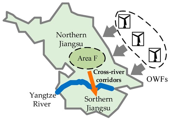
Figure 1.
Schematic of the power grid of Jiangsu Province.
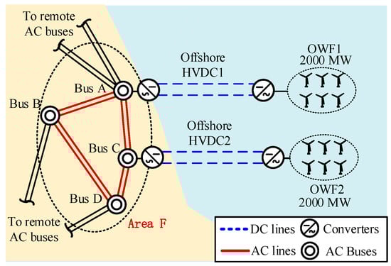
Figure 2.
Geographical network schematic of OWF integration into the northern power grid.
The electrical energy from offshore wind power will be mainly transmitted through 500 kV power grid lines. In addition to the previously mentioned Buses A and C, the 500 kV grid in Area F also features Buses B and D. An N-1 fault check was conducted on the 500 kV power grid in Area F with 4000 MW of offshore wind power integrated, and the results are shown in Table 1.

Table 1.
N-1 Security check results of the AC power transmission channels in Area F.
It can be seen from the check results that after the integration of offshore wind power, the A-B line in the Area F Power Grid fails to pass the N-1 check. Specifically, when one circuit of the double-circuit AC lines from A to B is out of service due to faults or maintenance, the other circuit will experience a serious overload phenomenon, which requires corresponding solutions.
2.2. Discussion on Conventional AC/DC Solutions
As previously mentioned, the northern and southern power grids of Jiangsu show a severe imbalance between power generation capacity and local load. Consequently, a fundamental solution to mitigate grid congestion in Area F in northern Jiangsu is to increase its power transmission capacity to the load-dense southern grid. This would directly alleviate the operational stress on the local grid caused by the large-scale integration of offshore wind power.
Technical solutions for enhancing the power transmission capacity of existing grid lines can be divided into two main categories: AC and DC solutions. AC solutions include replacing existing conductors with those of higher capacity, constructing new AC lines, and implementing reactive power compensation. The active power transmission limit of an AC line is governed by the well-known power-flow equation [27], which relates the per-unit active power p to the voltage magnitudes and phase angles at the two terminal AC buses:
where e1 and e2 represent the voltage magnitudes at the two terminal buses, respectively, and Δδ12 is the phase angle difference between these buses. scr1 and scr2 are the short-circuit ratios (SCRs) of the respective buses. β is the phase constant, and l is the line length.
According to Equation (1), the active power transmission on an AC line is positively correlated with the phase angle difference between its terminal buses, assuming constant voltage magnitudes and line lengths. In practice, however, this angle difference is constrained by system stability requirements (both transient and steady-state stability), necessitating operation within a phase angle limit that includes a specified security margin.
When the AC line is compensated with shunt reactors, series capacitors, and additional reactive power support, the per-unit active power p’ transmitted is given by the following equation:
where kp is the compensation degree of the shunt reactor, and kc represents the compensation degree of the series capacitor.
Equation (2) shows that reactive power compensation can enhance the transmission capacity of an AC line. However, due to risks such as line resonance, the compensation degree is severely limited. Consequently, this approach cannot achieve a substantial increase in the transmission capacity of existing AC lines.
In conclusion, the transmission capacity of AC lines is constrained not only by thermal limits but also by voltage drop and power angle stability requirements. Furthermore, the geographical constraint of the Yangtze River, which must be crossed by any transmission path from northern to southern Jiangsu, presents a severe challenge: the existing cross-river corridors are spatially limited and difficult to expand. Consequently, the AC solution offers limited potential for capacity enhancement within this confined space and carries the risk of exacerbating short-circuit currents at 500 kV buses. Therefore, it is inadequate for accommodating the large-scale power injection from OWF.
Given the limitations of the AC solution, a more feasible alternative is to implement an onshore, embedded VSC-HVDC system to transmit power to the southern grid of Jiangsu. Unlike AC transmission, the power transfer capacity of this embedded DC link is not constrained by voltage drop or power angle stability, thereby allowing the cross-river corridor to be utilized up to its thermal limit [28,29]. Figure 3 illustrates a scenario where an onshore VSC-HVDC system, which is independent of the marine HVDC, is constructed for wind power relief.
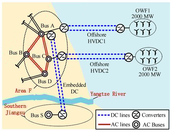
Figure 3.
Geographical network schematic of the OWF power relief solution based on an independent embedded DC system.
While technically feasible, this solution requires multiple converter stations that demand substantial land resources and high costs. The lack of coordinated control among independent HVDC systems also complicates dispatch, and routing power exchange through AC buses limits capacity and increases power losses. These issues reduce the cost-effectiveness of the solution, driving the need for a more integrated alternative.
3. The Overall Design of Hybrid Mono–Bipolar HVDC System
3.1. Topology Design of Hybrid Mono–Bipolar HVDC System
To enhance system economic efficiency and coordinated control performance, the offshore wind power transmission HVDC and the onshore embedded DC are integrated into a single hybrid HVDC system that extends from the OWF to inland areas. The main wiring scheme of the hybrid HVDC system is differentiated between its onshore and offshore segments to address distinct operational requirements. For the onshore part of the system, given its large transmission power capacity and failure-prone overhead lines (OHL), a complete shutdown would significantly affect power transmission to the southern Jiangsu and greatly threaten the safety and stability of the power grid. Therefore, a symmetric bipolar link with metallic return path scheme is adopted for its higher reliability. For the offshore part of the system, considering the difficulty in arranging offshore grounding electrodes and the high reliability of submarine cables, the offshore wind power transmission HVDC still adopting a conventional symmetric monopolar link scheme.
The topology of the proposed hybrid HVDC system is shown in Figure 4. The system comprises two main segments: an offshore wind power transmission DC system and an onshore embedded DC system. All converter stations employ half bridge sub-module based MMCs to meet key operational requirements, including power flow reversal and enhanced integration compatibility with weak grids or passive networks [23,30].
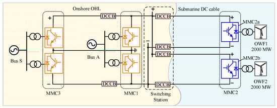
Figure 4.
Topology of proposed hybrid mono–bipolar HVDC system.
The offshore segment includes OWF 1, OWF 2, and offshore converter stations MMC2a and MMC2b, each connected to the collector system of one wind farm. This segment converts the wind power to DC for transmission to the onshore system. For simplicity, MMC2a and MMC2b are equivalently represented as a single converter station, MMC2, in the subsequent analysis. The onshore embedded segment consists of converter stations MMC1 and MMC3, connected to Bus A in grid F and Bus S in the southern grid of Jiangsu, respectively. The symmetric bipolar wiring mode of MMC1 and MMC3 is implemented using separate valve groups for the positive and negative poles, thereby ensuring redundancy in onshore power transmission. Given the inherent lack of fault current blocking capability in the half-bridge MMC, the proposed system is equipped with Direct Current Circuit Breakers (DCCBs) to enable the rapid interruption of fault current.
As shown in Figure 5, the system interconnects three AC grids: the northern power grid, the southern power grid, and the OWF. The proposed hybrid HVDC allows the power output from the OWF and the onshore generation sources in the northern grid of Jiangsu to complement each other, thereby enabling coordinated power transmission to the load center in the southern grid of Jiangsu.
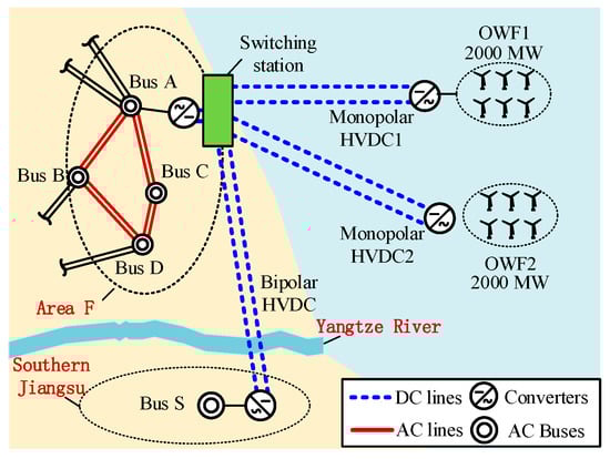
Figure 5.
Geographical network schematic of the proposed hybrid mono–bipolar HVDC system.
3.2. Techno-Economic Evaluation of Hybrid Mono–Bipolar HVDC System
To validate the effectiveness of the proposed hybrid HVDC system in alleviating offshore wind power surpluses and resolving the overload issue in Area F, an N-1 security check was conducted. The results, summarized in Table 2, demonstrate that after the hybrid HVDC system transmits sufficient power from Area F to Southern Jiangsu, all lines in Area F pass the N-1 check with relatively low loading levels. This confirms that the proposed system effectively alleviates the transmission burden on the coastal power grid.
Table 2.
N-1 Security check results of the transmission channels with the hybrid HVDC system.
On the premise that the hybrid HVDC can equally achieve the same power flow relief effect on the Area F power grid as the independent HVDC scheme, a comparison of their construction costs is presented in Table 3, with reference to relevant engineering cost data [31,32].
Table 3.
Economic analysis of the construction costs.
Compared with the scheme of constructing an independent embedded DC system, the hybrid HVDC scheme not only saves approximately 10% of the construction investment costs but also achieves equivalent improvements in power flow relief effect, thus realizing a better balance between economy and technical performance.
4. The Design of Operation Modes and Control Strategy
4.1. Operation Modes of Hybrid Mono–Bipolar HVDC System
4.1.1. Normal Operation Mode
In the normal operating mode, the system maintains a stable power transfer of 4000 MW to Bus S in the southern grid of Jiangsu. Under this mode, the offshore converter station MMC2 and the onshore sending-end station MMC1 both operate as rectifiers, transmitting power from the OWFs and the Area F grid, respectively. The receiving-end station MMC3 operates as an inverter, delivering power to Bus S.
Since offshore wind power generation is highly variable and often fails to reach its full capacity due to wind speed and weather conditions [33], the system is designed to compensate for these fluctuations. When the output from the OWFs decreases, the transmission power of MMC1 is increased accordingly to balance the deficit. This operating mode is illustrated in Figure 6a.
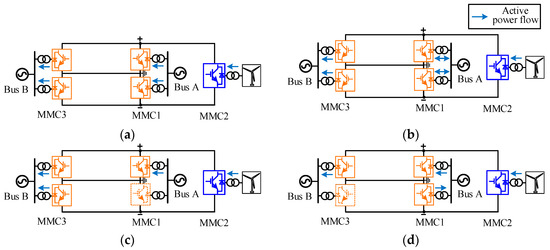
Figure 6.
Operation modes of the hybrid HVDC system: (a) Normal operation mode; (b) Onshore power support mode; (c) Asymmetrical operation mode (MMC1n blocked); (d) Asymmetrical operation mode (MMC3n blocked).
4.1.2. Onshore Power Support Mode
Should the Area F grid experience a sudden load increase or a generation unit outage, it will face a significant power deficit and require external active power support. In this scenario, the system enters the onshore power support mode.
In this mode, the sending-end converter MMC1 is switched to inverter operation to draw power from the HVDC system for Area F. The receiving-end converter MMC3 prioritizes inverter operation to ensure that power delivery to Bus S in the southern grid of Jiangsu is maximally maintained. The offshore converter MMC2 remains in rectifier mode, continuing to transmit wind power.
If the offshore wind output is low or the power deficit in Area F is severe, MMC3 can be switched to rectifier operation, as long as the southern grid of Jiangsu remains stable, to draw power from the south and support Area F. This operating mode is illustrated in Figure 6b.
4.1.3. Asymmetrical Operation Mode
The system enters an asymmetric operating mode when one pole of the onshore HVDC is shut down for maintenance or a fault. In this mode, the non-fault pole continues normal operation, while the remaining converters in the faulty pole sustain the DC voltage of that pole, enabling the offshore symmetric monopolar HVDC to remain in operation and ensuring uninterrupted wind power transmission. The corresponding operating scenarios are illustrated in Figure 6c,d.
4.2. Control Strategy of Hybrid Mono–Bipolar HVDC System
4.2.1. Basic Control Strategy
In addition to the decoupled current control which serves as the basic VSC control strategy presented in Appendix A, to ensure coordinated operation between the offshore and onshore HVDC segments and achieve the rated power transfer to the southern grid of Jiangsu, a specific control strategy should be designed for the hybrid HVDC system.
Since all wind turbines in the connected OWFs are of the grid-following type, they rely on their phase-locked loops (PLLs) to synchronize with a stable AC voltage reference. Consequently, the offshore converter stations MMC2a and MMC2b should both employ a Voltage-Frequency (VF) control scheme to establish a stable AC voltage for the wind farms.
Among the onshore converters, MMC1 is designated as the master station and employs constant DC voltage control on both poles to maintain the DC link voltage at its rated value. MMC3, as the slave station, regulates the power transfer to its setpoint via constant active power control on both poles. The control strategies for each converter station are illustrated in Figure 7.
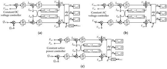
Figure 7.
Basic control strategy of MMC stations: (a) Control strategy of MMC1; (b) Control strategy of MMC2; (c) Control strategy of MMC3.
Under this control strategy, the onshore receiving-end converter station maintains a near-rated power reception of 4000 MW. Consequently, the system autonomously compensates for fluctuations in OWF output. A reduction in power from the offshore converters is automatically balanced by a corresponding increase from the onshore sending-end converter, requiring no mode switching or operator intervention.
4.2.2. Control Strategy of Onshore Power Support Mode
In the onshore power support mode, the system retains the same fundamental control structure as mentioned above: MMC1, MMC2, and MMC3 maintain constant DC voltage, VF grid-forming, and constant active power control, respectively. By adjusting the power reference setpoint of MMC3, the power flow of the HVDC system is redirected to enable active power support for the Area F grid from MMC1.
Given that the active power losses in the HVDC lines and converters are negligible compared to the total transmission capacity, the node power balance equation at the common DC bus of the switching station can be derived as:
where PMMC1, PMMC2, and PMMC3 denote the active powers at converter stations MMC1, MMC2, and MMC3, respectively, whose positive directions are consistent with those in Figure 6a.
Define the active power support that MMC1 feeds back to the AC power grid at Bus A after the fault as P’MMC1, which satisfies:
where PMMC1N is the rated value of the active power transmitted by MMC1, and ΔPMMC1 is the increment of the transmitted power at MMC1 after the support.
It can be obtained from Equation (3) that ΔPMMC1 satisfies:
where ΔPMMC3 and ΔPMMC2 are the respective power increment at MMC3 and MMC2.
Combining Equations (4) and (5), the active power support amount P’MMC1 satisfies:
Since the wind farm output at MMC2 is uncontrollable, ΔPMMC2 fluctuates in accordance with the actual wind farm output. Therefore, the active power support ΔPMMC3 at MMC3 must be adjusted in real-time according to Equation (6) to compensate. Figure 8 shows the corresponding control structure of MMC3 with the active power compensation.
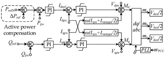
Figure 8.
Control strategy of MMC3 with active power compensation.
4.2.3. Control Strategy of Asymmetrical Operation Mode
In the hybrid DC system, the direct parallel connection of the onshore bipolar and offshore monopolar segments creates a power coupling during asymmetric operation, which necessitates a dedicated coordinated control strategy.
Given the symmetry of the onshore bipolar DC system, the following analysis only focuses on the outage of the negative pole converter, MMC1n. Under this contingency, converter MMC3n must maintain the negative pole DC voltage to ensure system operation. The corresponding power flow of the hybrid HVDC system is illustrated in Figure 9.
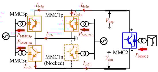
Figure 9.
DC Power flow under asymmetric operation mode.
Under this operating condition, the DC currents in the system adhere to Kirchhoff’s Current Law (KCL), yielding Equation (7).
Assuming ideal conditions where line losses and voltage drops are negligible, the power at each converter station satisfies Equation (8).
From Equations (7) and (8), the coupling relationship between the power flows of the converters during asymmetrical operation can be derived as:
To prevent bias voltage in the offshore symmetric monopolar system during asymmetric operation, the condition |Vp/Vn| = 1 must be maintained. Substituting this into Equations (9) and (10) yields:
Based on the equations above, when the system enters asymmetric operation due to the outage of MMC1n, the remaining converters continue to share equally half of the active power injected by the OWF. The negative-pole active power is fully received by MMC3n, while the positive-pole power is shared between MMC1p and MMC3p according to Equation (12). The power coupling relationship under an outage of MMC3n is analogous and can be derived similarly.
Following the outage of converter MMC1n, which employs constant DC voltage control, MMC3n should assume control of the DC voltage of the negative pole. For this purpose, a redundant constant DC voltage controller is incorporated into MMC3n’s control scheme, as shown in Figure 10. Upon the outage of MMC1n, the negative-pole DC voltage will deviate beyond its normal operating range (0.95 p.u.~1.05 p.u.), triggering MMC3n to switch to its backup voltage control mode and thus transition to the master station. Similarly, MMC3p incorporates an analogous redundant control strategy.
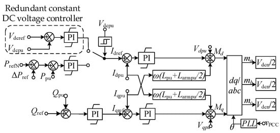
Figure 10.
Control strategy of MMC3 with redundant constant DC voltage control.
4.2.4. DC Fault Ride-Through Strategy
As mentioned in Section 3.1, multiple sets of DC circuit breakers (DCCBs) are installed in the switching stations connecting the offshore and onshore segments. Specifically, Specifically, all DCCBs are installed at the DC bus outlets of MMC1. Based on the system’s requirements for current breaking capability, operation time, and cost-effectiveness, the hybrid topology was selected for DCCBs [34].
The proposed DC fault ride-through strategy employs the coordinated operation of DCCBs and forced blocking of MMCs, with specific responses varying according to the fault location. For a pole-to-ground fault on the onshore OHL, the DCCB on the faulty pole trips, while the corresponding sub-converter of MMC3 (e.g., MMC3p or MMC3n) blocks mandatorily. Additionally, the Neutral Bus Switch (NBS) at the blocked sub-converter must be opened to isolate the sub-converter from the metallic return link [35]. In case a pole-to-ground fault occurs on the DC submarine cables in the offshore segment, all DCCBs connected to the bipolar cables trip to completely interrupt the fault current with MMC2 blocked. The fault ride-through strategy is shown in Figure 11.
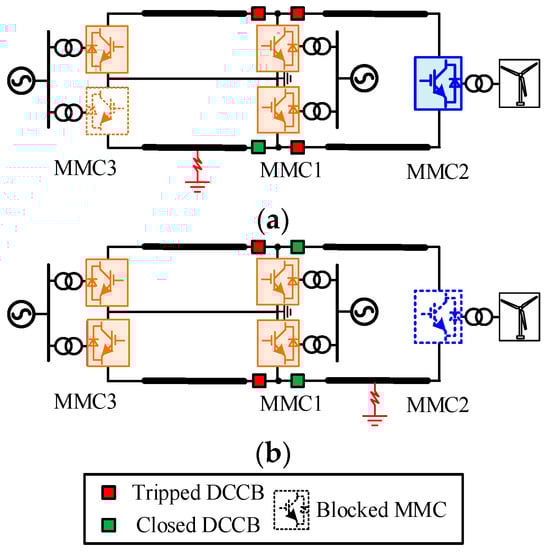
Figure 11.
Diagram of the DC fault ride-through strategy: (a) pole-to-ground fault on the onshore OHL; (b) pole-to-ground fault on the submarine cable.
5. Case Studies
In this section, the hybrid mono–bipolar HVDC system and the corresponding operation modes and control strategies previously proposed are verified through simulations. An electromagnetic transient simulation model of the hybrid HVDC system is established in PSCAD/EMTDC, where the parameters of converters and transmission lines in the simulation model are shown in Table 4 and Table 5, respectively.
Table 4.
Main parameters of the converters.
Table 5.
Main parameters of the DC transmission lines.
5.1. Case 1: Normal Operation
Firstly, we examine the system performance under rated operating conditions, where the OWFs are expected to deliver 4000 MW. In the simulation, the wind farms begin power generation at t = 6 s, ramp up smoothly, and reach rated output at t = 6.5 s. We present the key electrical waveforms in Figure 12.
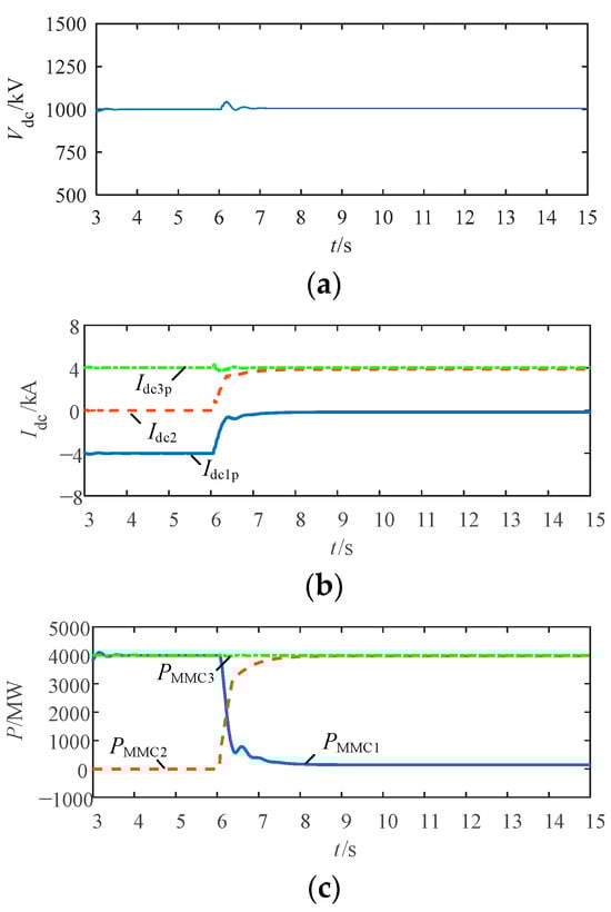
Figure 12.
Simulation results of case 1: (a) DC voltage; (b) DC current (represented by the positive pole current during symmetric operation); (c) active power of each converter station.
Figure 12 demonstrates stable system operation under rated operation conditions. All electrical quantities remained within expected ranges, and the power outputs of the converter stations closely tracked their control objectives, confirming the effectiveness of the proposed control strategy.
5.2. Case 2: Wind Power Fluctuation
In the simulation case of the wind power fluctuation, it is still set that the OWFs start at t = 6 s, with their output power reaching 4000 MW at t = 6.5 s. At t = 10 s, the total output power of the two wind farms drops to 0.6 p.u (2400 MW) and remains stable. Meanwhile, considering the communication delay, it is set that the reference value of power control at MMC1 starts its adjustment process at 10.3 s. The corresponding simulation results are shown in Figure 13.
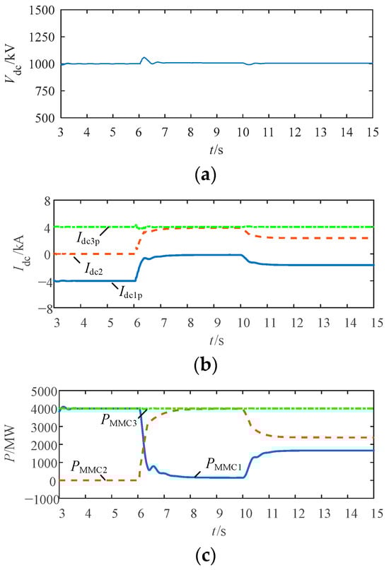
Figure 13.
Simulation results of case 2: (a) DC voltage; (b) DC current; (c) active power of each converter station.
The results clearly show that following the wind farm output reduction, MMC1 increases its active power injection accordingly to compensate for the power deficit. The response aligns well with the control design objectives, and the system maintains stable operation throughout the entire power adjustment process.
5.3. Case 3: Onshore Power Support
For the onshore power support scenario, the simulation is configured with the system entering support mode when the total OWF output drops to 0.6 p.u. (2400 MW). The wind farms start at t = 6 s, ramp to 0.6 p.u. by t = 6.5 s, and remain stable. At t = 10 s, MMC1 initiates the onshore power support mode, delivering a total of 1000 MW to Bus A. The simulation results for this scenario are summarized in Figure 14.
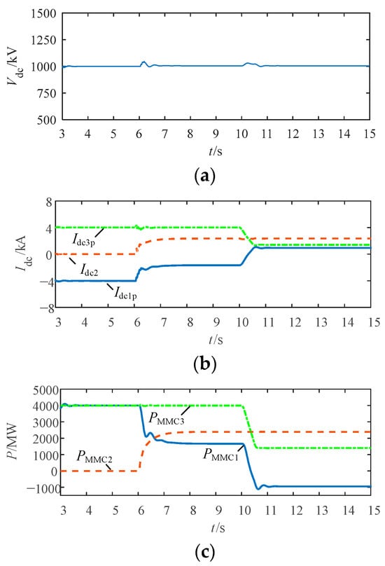
Figure 14.
Simulation results of case 3: (a) DC voltage; (b) DC current; (c) active power of each converter station.
The results confirm that MMC1 successfully switches from rectifier to inverter operation, delivering the scheduled active power support to the onshore grid. The system maintains stable operation throughout the power reversal process, validating the effectiveness of the control strategy.
5.4. Case 4: Asymmetrical Operation
For the asymmetric operation scenario, the wind farms start at t = 6 s and ramp up to 0.6 p.u. (2400 MW) by t = 6.5 s and remaining stable. At t = 10 s, MMC1n is shut down, after which MMC3n automatically assumes backup DC voltage control once the system voltage reaches the preset threshold. The simulation results for this scenario are summarized in Figure 15.
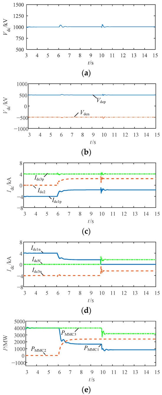
Figure 15.
Simulation results of case 4: (a) DC voltage; (b) bipolar DC voltage to ground; (c) DC current in the positive pole; (d) DC current in the negative pole and neutral metallic return line; (e) active power of each converter station.
The simulation results demonstrate that following the outage of MMC1n and the subsequent transition to asymmetric operation, MMC3n promptly activates its backup constant DC voltage control. This ensures stable operation of the onshore negative DC pole, with MMC3n continuing to receive half of the power (1200 MW) transmitted by the offshore HVDC. Meanwhile, MMC1p and MMC3p maintain their original control strategies. Supported by the power supplement from MMC1p, MMC3p retains its full rated transmission capacity of 2000 MW. As a result, the system preserves a high level of power transmission capability even under a one-pole outage condition.
5.5. Case 5: Onshore OHL Pole-to-Ground Fault
For the onshore OHL pole-to-ground fault scenario, the wind farms start at t = 6 s and ramp up to 0.6 p.u. (2400 MW) by t = 6.5 s and remaining stable. At t = 9.995 s, a negative pole to ground fault is applied on the DC outlet side of MMC1n. At t = 10 s, the system detects the DC fault and the DC fault ride-through strategy comes into operation. The simulation results for this scenario are summarized in Figure 16.
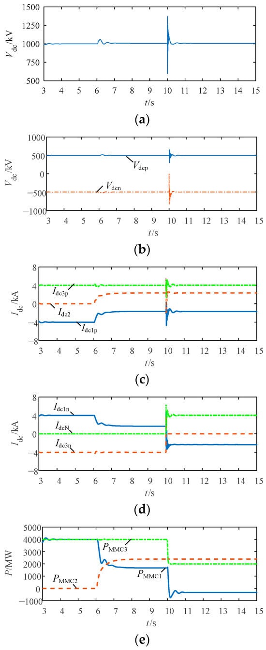
Figure 16.
Simulation results of case 5: (a) DC voltage; (b) bipolar DC voltage to ground; (c) DC current in the positive pole; (d) DC current in the negative pole and neutral metallic return line; (e) active power of each converter station.
The simulation results demonstrate that the system experiences significant transient impacts from an onshore negative pole to ground fault, with a peak value of 1.6 p.u. Observed in the DC voltage of the negative pole. Upon fault detection, the DCCB of the faulty pole trips and the corresponding converter (MMC3n) blocks according to the fault ride-through strategy, achieving coordinated fault clearance. The system then successfully recovers stable operation at t = 10.5 s. After the fault, MMC3n remains blocked while MMC3p continues operating at its full rated capacity of 2000 MW, maintaining system stability in asymmetric operation mode. These results confirm the fault ride-through capability of the system under the tested contingency condition.
6. Conclusions
This paper proposes a novel hybrid mono–bipolar HVDC system as a technically robust and economically feasible solution for strengthening the coastal power grid and enhancing its power accommodation capacity to integrate large-scale offshore wind power. This study is grounded in a concrete case study of the Jiangsu grid, where N-1 contingency analysis first identified a critical need for power transfer capability enhancement, establishing the deployment rationale. A specific system topology was subsequently designed and evaluated through a detailed techno-economic analysis, which confirmed its dual advantage: effectively strengthening the coastal grid while demonstrating superior cost-effectiveness over conventional expansion alternatives. Critically, a corresponding coordination control strategy was devised to ensure seamless operation across multiple defined modes, including symmetric and asymmetric operating conditions. Electromagnetic transient simulations comprehensively validated that the system maintains stable and robust performance in all scenarios, successfully achieving the predefined control objectives for power regulation and fault management.
Future research will focus on aspects not yet covered by this paper, including comprehensive transient studies of AC/DC faults in the proposed hybrid HVDC system and an assessment of their potential dynamic impacts on the stability of coastal power grids. Experimental validation through hardware-in-the-loop testing is also considered a critical next step for future research and technology demonstration.
Author Contributions
Conceptualization, Z.P.; methodology, W.S.; investigation, W.Z. and Z.X.; writing—original draft preparation, X.H.; writing—review and editing, X.H., W.Z. and Q.W.; project administration, X.H. All authors have read and agreed to the published version of the manuscript.
Funding
This research was funded by the Science and Technology Project of State Grid Electric Power Co., Ltd. (J2023119).
Data Availability Statement
The data that support the findings of this study are available from the corresponding author upon reasonable request.
Acknowledgments
The authors would like to thank Wang Xu of State Grid Jiangsu Electric Power Co., Ltd., Economic Research Institute, for his Supervision and his pivotal role in Funding acquisition for this study.
Conflicts of Interest
Xingning Han, Zhuyi Peng, Wenjia Zhang, Wentao Sun, Qian Wu, and Zhenjian Xie are employed at Economic Research Institute of State Grid Jiangsu Electric Power Co., Ltd. The remaining authors declare that the research was conducted in the absence of any commercial or financial relationships that could be construed as a potential conflict of interest. The authors declare that this study received funding from Economic Research Institute of State Grid Jiangsu Electric Power Co., Ltd. The funder was not involved in the study design, collection, analysis, interpretation of data, the writing of this article or the decision to submit it for publication.
Appendix A
This appendix provides a detailed mathematical derivation of the decoupled current control for a point-to-point VSC-HVDC system [36]. The focus is on the transient modeling in the synchronous reference frame and the design of decoupled controllers for both the rectifier and inverter stations. It should be noted that although the derivation is based on two-level VSCs, the resulting control strategy has been demonstrated to be equally applicable to MMCs [37]. The topology of the VSC-HVDC system is shown in Figure A1.

Figure A1.
The topology of the VSC-HVDC system.
For the simplicity in derivation, the VSC system is considered idealized and symmetric, and its parameters meet the following equations:
The transient mathematical model of the VSC in the d-q synchronous reference frame is derived under the assumption that the resistance of the converter inductor and switching losses are negligible. Using the synchronous frame transformation, the model is expressed as:
where vsd and vsq are the bus voltages in the d and q axes, respectively; vcd and vcq represent the fundamental components of the converter AC-side voltages; isd and isq denote the AC currents; and ω is the angular frequency.
The synchronous reference frame transformation matrix T, with θ as the phase angle of the source voltage space vector, is defined as:
According to the instantaneous power theory, the active and reactive power on the AC-side of the VSC can be expressed as:
Under balanced network conditions, the d-axis is aligned with the source voltage space vector, resulting in vsd = Vs and vsq = 0, where Vs is the amplitude of the source phase voltage. (A4) can be then simplified as:
This shows that active and reactive power can be independently controlled by regulating the active current isd and the reactive current isq, respectively.
For the rectifier station, a decoupled controller based on input-output feedback linearization is designed. According to (A2) the current dynamics in the d-q axes are rewritten as:
To achieve decoupled control, new input variables xd and xq are introduced, leading to a linearized system described by:
Substituting (A6) into (A7), the desired fundamental components of voltage on the ac side of the converter are:
(A8) enables decoupled current control with feed-forward compensation, whose performance is affected by the parameters λ1 and λ2. While xd and xq correspond to the active and reactive current references from the outer control loops. The outer loops include a DC voltage regulator and a reactive power controller, both employing PI control to generate isdref and isqref, respectively.
For the inverter station, a constant AC voltage controller is designed based on the steady-state model in the synchronous reference frame. Under balanced network conditions, the steady-state mathematical model is expressed as:
Assuming the d-axis is aligned with the source voltage. With vsq = 0 and vsd = Vs2, where Vs2 is the amplitude of the desired AC voltage, the equation (A9) can be simplified as:
Based on (A10), a PI regulator is used to control the AC voltage amplitude, generating the reference values for the converter voltages. This approach ensures stable and balanced AC voltage output under varying load conditions.
References
- Huang, S.; Zhang, Y.; Feng, Y.; Gao, J. Review of the technological development of permanent magnet wind generator. J. Electr. Eng. 2025, 20, 22–42. (In Chinese) [Google Scholar]
- TenneT’s 900 MW Dolwin6 Goes Into Operation. Available online: https://www.offshorewind.biz/2023/09/26/tennets-900-mw-dolwin6-goes-into-operation (accessed on 20 November 2025).
- Li, G.Q.; Ye, H.; Bin, Z.J. High-Frequency Oscillation Mechanism Analysis of Wind Farm-Side MMC Station Considering Converter Transformer Stray Capacitance. Int. J. Electr. Power Energy Syst. 2023, 153, 109179. [Google Scholar] [CrossRef]
- HVDC Monita Works on Converter Station for HV Power Transmission. Available online: https://elnosgroup.com/en/projects/hvdc-monita-works-on-converter-station-for-hv-power-transmission/ (accessed on 20 November 2025).
- Pecoraro, G.; Pascucci, A.; Carlini, M.E.; Contu, M.; Cortese, M.; Gnudi, R.; Allella, F.; Bruno, G.; Michi, L. HVDC Link Between Italy and Montenegro: Impact of the Commissioning on the Real-Time Operation. In Proceedings of the 2019 AEIT International Annual Conference (AEIT), Florence, Italy, 18–20 September 2019; pp. 1–6. [Google Scholar] [CrossRef]
- Glaum, P.; Neumann, F.; Brown, T. Offshore Wind Integration in the North Sea: The Benefits of an Offshore Grid and Floating Wind. In Proceedings of the 2023 19th International Conference on the European Energy Market (EEM), Lappeenranta, Finland, 6–8 June 2023; pp. 1–7. [Google Scholar] [CrossRef]
- Rajagopalan, P. Challenges in Grid Integration of Offshore Wind in Tamil Nadu and Gujarat for Policy Makers and Transmission Planners. In Proceedings of the 2017 7th International Conference on Power Systems (ICPS), Pune, India, 21–23 December 2017; pp. 206–211. [Google Scholar] [CrossRef]
- Qin, H.; Huang, L.; Wang, T.; Wu, Y. Study on Reasonable Aggregation Capacity of Offshore Wind Power Directly Sending to Load Centers. In Proceedings of the 2024 International Conference on Electrical Drives, Power Electronics & Engineering (EDPEE), Athens, Greece, 27–29 February 2024; pp. 881–886. [Google Scholar] [CrossRef]
- Nazir, M.; Enslin, J.H.; Hines, E.; McCalley, J.D.; Lof, P.-A.; Garnick, B.K. Multi-Terminal HVDC Grid Topology for Large Scale Integration of Offshore Wind on the US Atlantic Coast. In Proceedings of the 2022 7th IEEE Workshop on the Electronic Grid (eGRID), Auckland, New Zealand, 29 November–2 December 2022; pp. 1–5. [Google Scholar] [CrossRef]
- Kuo, M.-T. Improving the Grid-Connected Capacity of Offshore Wind Farms: A Case Study of the Taiwan Power System. IEEE Ind. Appl. Mag. 2022, 28, 27–43. [Google Scholar] [CrossRef]
- Wang, Z.; Huang, J.; Cheng, L.; Hu, W.; Cai, H.; Han, X. Planning and application of embedded DC transmission technology in the provincial transmission power grid. Electr. Power Eng. Technol. 2022, 41, 65–74. (In Chinese) [Google Scholar] [CrossRef]
- Cai, H.; Peng, Z.; Zhang, W.; Qi, W.; Xie, Z.; Huang, J.; Xu, Z. Study on application of voltage-source-controlled high-voltage direct-current transmission technology in Jiangsu power grid. Power Capacit. React. Power Compens. 2019, 40, 90–94. (In Chinese) [Google Scholar] [CrossRef]
- Xia, X.; Ye, H.; Qiu, Q.; Zhang, J.; Yin, Z.; Nie, Z.; Li, S.; Li, H.; Wang, L.; Xiao, L. Research on source-end energy storage configuration method of wind-solar power stations. Adv. Technol. Electr. Eng. Energy 2025, 44, 1–12. (In Chinese) [Google Scholar] [CrossRef]
- Tu, R.; Xiang, W.; Zheng, S.; Lei, Y.; Han, X.; Zhang, W.; Wen, J. Hybrid multi-terminal HVDC integrated system for large-scale offshore wind farms based on DC bus. Power Syst. Technol. 2025, 1–12. (In Chinese) [Google Scholar] [CrossRef]
- Han, X.; Chen, X.; McElroy, M.B.; Liao, S.; Nielsen, C.P.; Wen, J. Modeling formulation and validation for accelerated simulation and flexibility assessment on large scale power systems under higher renewable penetrations. Appl. Energy 2019, 237, 145–154. [Google Scholar] [CrossRef]
- Sun, P.; Fan, Y.; Sun, X.; Niu, S.; Yang, P.; Zhang, Z.; Guo, J. Equivalent renewable energy accommodating capability and its engineering application. Adv. Technol. Electr. Eng. Energy 2023, 42, 79–86. (In Chinese) [Google Scholar]
- Liao, S.; Yao, W.; Han, X.; Fang, J.; Ai, X.; Wen, J.; He, H. An improved two-stage optimization for network and load recovery during power system restoration. Appl. Energy 2019, 249, 265–275. [Google Scholar] [CrossRef]
- Caprivi Link. Available online: https://www.nampower.com.na/Page.aspx?p=219 (accessed on 20 November 2025).
- Cai, H.; Han, X.; Xu, S.; Qi, W.; Xie, Z. Embedded DC Transmission Technology and Its Application in Jiangsu Power Grid. In Proceedings of the Annual Meeting of CSEE Study Committee of HVDC and Power Electronics (HVDC 2023), Nanjing, China, 22–25 October 2023; pp. 23–30. [Google Scholar] [CrossRef]
- Yu, J.; Karady, G.; Qin, J. Controls of Embedded HVDC System for System Dynamic Performance Enhancement. In Proceedings of the 2017 IEEE Power & Energy Society General Meeting, Chicago, IL, USA, 16–20 July 2017; pp. 1–5. [Google Scholar] [CrossRef]
- Wang, Z.; Ling, J.; Zheng, J.; Wang, C.; Kong, X.; Liu, Z.; Feng, X. Optimized DC Fault transient control strategy for embedded symmetric unipolar LCC-HVDC. Power Syst. Technol. 2025, 49, 1541–1550. (In Chinese) [Google Scholar] [CrossRef]
- Wang, Z.; Zhang, L.; Liu, X.; Li, Z. Power Flow Optimal Control Strategy for Regional Power Grid Transmission Interface Using “Embedded” HVDC. In Proceedings of the 2024 11th International Forum on Electrical Engineering and Automation (IFEEA), Shenzhen, China, 9–11 November 2024; pp. 525–529. [Google Scholar] [CrossRef]
- Watson, N.R.; Watson, J.D. An Overview of HVDC Technology. Energies 2020, 13, 4342. [Google Scholar] [CrossRef]
- Liu, W.; Li, Q.; Wang, X.; Zhang, F.; Li, L.; Yan, H. Application status and prospect of VSC-HVDC technology for large-scale offshore wind farms. Electr. Power 2020, 53, 55–71. (In Chinese) [Google Scholar]
- Wu, Q.; Bo, X.; Wu, Y.; Zheng, Y. Techno-economic analysis of far coast offshore wind power transmission modes. Electrotech. Electric 2024, 1–9+15. (In Chinese) [Google Scholar] [CrossRef]
- Fan, X.; Chi, Y.; Ma, S.; Fan, Y.; Li, Y.; Wang, C. Research and application of key technologies and technical standards for large-scale offshore wind farms connecting to power grid. Power Syst. Technol. 2022, 46, 2859–2870. (In Chinese) [Google Scholar] [CrossRef]
- Xu, Z. Dynamic Performance Analysis of AC/DC Power Systems; Machine Press: Beijing, China, 2004; pp. 15–30. [Google Scholar]
- Xu, Z. Overview of basic characteristics and application modes of DC power transmission. Electr. Power Constr. 2025, 46, 34–43. (In Chinese) [Google Scholar]
- Xu, Z.; Xu, F. Research on key technologies of AC-to-DC transmission lines conversion. High Volt. Eng. 2016, 42, 1–10. (In Chinese) [Google Scholar]
- Yan, J.; Shi, X.; Liu, T.; Wang, Z.; Zhang, L.; Lin, L. Weak grid characteristic analysis and operating mode selection for voltage support enhancement of wind farms connected to MMC-HVDC during asymmetric faults. IEEE Trans. Power Electron. 2025, 41, 2629–2647. [Google Scholar] [CrossRef]
- Ma, X.; Zhang, Z.; Wu, M.; Xia, L.; Liao, X.; Chen, C.; Xu, B.; Hu, C. Technical and economical comparisons of 2 GW offshore wind power transmission schemes by symmetrical monopole and symmetrical bipolar VSC-HVDC. South. Power Syst. Technol. 2024, 18, 30–38. (In Chinese) [Google Scholar] [CrossRef]
- Shi, X.; Xiang, W.; Wen, J. Economic Analysis of Large-Scale Offshore Wind Power Integration Schemes. In Proceedings of the 2024 International Conference on HVDC, Urumqi, China, 8–10 August 2024; pp. 197–202. [Google Scholar]
- Rao, Z.; Wang, K.; Tan, J.; Li, J.; Yang, Z.; Meng, W. Non-parametric kernel density estimation and analysis of Guangdong offshore wind power output based on optimal bandwidth. Acta Energiae Solaris Sinica 2023, 44, 274–282. (In Chinese) [Google Scholar] [CrossRef]
- Mohammadi, F.; Rouzbehi, K.; Hajian, M.; Niayesh, K.; Gharehpetian, G.B.; Saad, H.; Ali, M.H.; Sood, V.K. HVDC Circuit Breakers: A Comprehensive Review. IEEE Trans. Power Electron. 2021, 36, 13726–13739. [Google Scholar] [CrossRef]
- Vestergaard, O.; Lundberg, P. Maritime Link The First Bipolar VSC HVDC with Overhead Line. In Proceedings of the 2019 AEIT HVDC International Conference (AEIT HVDC), Florence, Italy, 9–10 May 2019; pp. 1–4. [Google Scholar] [CrossRef]
- Chen, H. Research on the Control Strategy of VSC Based HVDC System Supplying Passive Network. In Proceedings of the 2009 IEEE Power & Energy Society General Meeting, Calgary, AB, Canada, 26–30 July 2009; pp. 1–4. [Google Scholar] [CrossRef]
- Dai, L.; Deng, C.; Chao, W.; Wang, J.; Huang, J. Research on Control Strategy and Simulation of MMC-HVDC System Based on Battery Energy Storage System. In Proceedings of the 2023 3rd International Conference on Electrical Engineering and Control Science (IC2ECS), Hangzhou, China, 29–31 December 2023; pp. 717–721. [Google Scholar] [CrossRef]
Disclaimer/Publisher’s Note: The statements, opinions and data contained in all publications are solely those of the individual author(s) and contributor(s) and not of MDPI and/or the editor(s). MDPI and/or the editor(s) disclaim responsibility for any injury to people or property resulting from any ideas, methods, instructions or products referred to in the content. |
© 2025 by the authors. Licensee MDPI, Basel, Switzerland. This article is an open access article distributed under the terms and conditions of the Creative Commons Attribution (CC BY) license (https://creativecommons.org/licenses/by/4.0/).