Abstract
In this paper, the effect of eddy-current losses of permanent magnets (PMs) is studied by conducting analyses and experiments. PM segmentation is used to reduce eddy-current losses. Nowadays, many researchers are focusing on improving the efficiency and torque of permanent magnet synchronous motors (PMSMs), particularly in electric vehicle applications. This study evaluates PM eddy-current losses of an in-wheel-type PMSM designed for light electric vehicle (LEV) propulsion. Improving output torque and efficiency is essential in this type of direct-drive application. The eddy-current losses of PMs can be reduced by forming PMs as electrically isolated magnet segments. PM segmentation leads to shorter paths and reduces the values of eddy-currents, creating reduced magnetic losses. The improvement in torque production capability also implies an improvement in efficiency. To investigate the validity of PM segmentation, a three-dimensional (3D) finite element analysis (FEA) software is used for non-segmented (monolithic) and segmented cases. The experimental study is conducted using monolithic PM and segmented PM rotor assemblies. This study demonstrates the contribution of PM segmentation to torque production.
1. Introduction
The automotive industry is in a rapid transition phase due to the well-known problems associated with fossil fuels, i.e., limited resources, low conversion efficiency, and negative environmental effects. This has prompted research efforts focused on new fuel types and, of course, on electric vehicles. Nowadays, electric vehicles are the focus of individuals and governing bodies. The development of electric vehicle technology can be simply divided into three main parts: batteries, electric powertrains, and charging systems. An obvious bottleneck of electric vehicle technology stems from the troubled nature of lithium-ion batteries. However, luckily, capacity problems are expected to be solved to a great extent. Although electric motor technology has clearly proved its superiority, there are still areas that need to be researched further, especially with regard to efficiency, compactness, and high-performance control [1,2,3].
Permanent magnet synchronous motors (PMSMs) and brushless DC motors (BLDCMs) are the first choices for electric vehicle propulsion due to their improved performance. PMSMs are used in most passenger vehicles because of their superior power density, high efficiency, high field-weakening, and regenerative braking capabilities. On the other hand, BLDCMs are suitable for low-speed light electric vehicle (LEV) applications due to their compact structure, simpler control system, and limited field-weakening feature [4,5,6]. Nowadays, it is not surprising to see that a lot of scientific research is directed to these motor types. Research efforts are mostly focused on optimizing efficiency over the whole drive range, improving power density, and creating compact designs [7,8,9].
Among different PMSM topologies, in-wheel (hub-type) PMSMs have recently attracted significant attention. Hub-type BLDC motors, as special types of PMSMs, are dominant in propulsion systems of LEVs, such as e-bikes, e-scooters, and small electric cars. To improve the dynamic performance of BLDC motors, studies have focused on optimizing many design criteria, especially the rotor and stator structure. Most studies rely on FEA of electromagnetic structures. This has led to the emergence of several commercial analytical software packages [10,11]. Those efforts have resulted in many high-performance motor designs and many researchers have verified that the experimental results and analysis results agree in most cases.
In the design optimization process of electric motors, the main focus points are efficiency, torque production, speed, and power density. Design optimization can be carried out by altering many design parameters, such as rotor and/or stator structures, dimensions, materials, the number of turns of windings, etc. The only way to improve efficiency is by minimizing losses, and this implies maximizing output power for a given input power. For direct-drive electric motors, the speed and range of speed change are defined by the nature of the application, and they are fixed. Therefore, changing the speed is not a case for efficiency optimization, and the sole way to improve the torque value is to maximize the output power. The main target is to produce more torque with less current due to the dominance of copper losses among other loss types. This yields another goodness factor of design: maximum torque per ampere (MTPA). Thanks to permanent magnets, BLDC motors have exceptionally low reactive power values because creating an excitation magnetic field is not necessary for torque production. So, it is possible to say that PM motors have inherently low copper losses and higher efficiencies. But of course, the quest for a higher-efficiency electric motor is a never-ending endeavor and designers can deal with extremes of design such as losses caused by permanent magnets.
Eddy-current loss in permanent magnets is another loss component caused by rotor motion. PM flux is subject to change because of the varying operating points of PMs during the motor operation. This variation creates eddy-currents in PMs and eventually causes losses. Thanks to the amorphous structure and relatively high resistivity of rare earth PMs, this loss is quite low but still present. PM eddy losses are more prominent in surface-mounted magnet motors due to their direct exposure to air-gap flux. Both motor speed and stator tooth structure affect the amount of that loss to a significant extent [12,13].
Researchers also studied the segmented structure of V-type embedded PMs in interior permanent magnet synchronous motors (IPMSMs) as well as surface-mounted PM motors. It has been suggested that magnet dimensions have an impact on eddy-current losses [14]. Naturally, motors with larger axial lengths are subject to higher PM eddy-current losses. There are numerous publications that discuss those findings by means of finite element analyses and experimental studies. In short, it is concluded that PM eddy-current loss comprises a significant portion of total losses [15,16,17].
This research focuses on the torque increase in brushless permanent magnet motors by means of a special type PMSM, i.e., an in-wheel motor for LEV propulsion. The goal is to optimize the shaft torque performance of the motor using a multi-objective optimization algorithm. When examining the factors affecting BLDC motor output parameters, it can be seen that they are influenced by factors such as correlations between different design parameters or the mutual compatibility of ferromagnetic materials. Therefore, these parameters are important factors in design optimization. For example, the width and length dimensions of permanent magnets, a key component of PMSMs, are crucial in design. Their sensitivities must be calculated separately, and their axial or radial orientation is determined accordingly. Furthermore, the mutual interaction of these two parameters with shaft torque also differs. This demonstrates a high correlation between the mentioned parameters [18]. There are many different methods for electric motor design optimization. One of these is the Hill Climbing optimization method. It can be used to optimize structural parameters at multiple levels and increase optimization accuracy. The Hill Climbing algorithm is best suited for in-wheel motor design parameters where volumetric space is limited. The Hill Climbing algorithm relies on a local search process to determine the highest local and global values by varying design parameters [19]. In this method, initial parameters are evaluated and selected and then modified in various applicable steps towards the target value or increments. By varying the parameters, local maximums, plateaus, and global maximums are determined. When multiple parameters are present, varying multiple parameters together or a single parameter individually can be considered [20,21]. Increasing torque in in-wheel PMSMs is challenging due to spatial constraints. It is anticipated that reducing the eddy-current paths affecting the electric motor output parameters will reduce these losses, thereby increasing both efficiency and torque. In permanent magnet electric motors, the eddy-current effect is most pronounced on the magnetic flux paths. In this study, the magnet on the tread bar of a radially arranged in-wheel PMSM was axially partitioned, thus shortening the eddy-current paths.
In-wheel PMSMs, also referred to as hub-type motors, differ from conventional PMSM topologies in that the motor is directly integrated into the wheel without requiring a mechanical transmission or differential system. This feature provides advantages such as reduced drivetrain losses, improved packaging, and higher total efficiency, which make them particularly suitable for light electric vehicles. However, unlike conventional PMSMs, which benefit from a relatively wider range of design options, in-wheel PMSMs are subject to strict spatial constraints, increased thermal challenges, and higher requirements for torque density and robustness against road-induced vibrations. Over the past three years, research efforts on PMSM torque optimization for LEVs have focused on various strategies such as advanced slot/pole combinations, PM segmentation to mitigate eddy-current losses, multi-objective optimization methods for maximizing torque per ampere, and novel cooling structures to address thermal bottlenecks [22,23,24,25]. These studies highlight that achieving higher torque density in hub-type PMSMs requires not only optimization of electromagnetic design parameters but also careful consideration of structural limitations unique to in-wheel applications.
A 3.2 kW, 150 V DC-link voltage PMSM for light electric vehicles was used in this study. A unique aspect of this study is that there is no other study in the literature that has improved the torque value of in-wheel PMSMs through axial partitioning. Furthermore, the proposed design is both simulated and implemented, verifying the hypothesis that eddy-current reduction enhances the torque of PMSM, which is the focus of this study.
This article begins with a literature review on the importance of in-wheel PMSM and its torque enhancement, and the motivation for the study. The second section describes the relationship between the axial magnet distribution in the PMSM rotor and its effects on motor output parameters. The third section examines electromagnetic analysis and the effects of different axial distributions on torque change. The fourth section covers the differences between axial magnet distributions and the undivided structure. The final section covers comments and conclusions.
2. The Effect of Axial Segmentation on the In-Wheel PMSM Torque
Torque is defined as the force that creates rotational motion in mechanical systems multiplied by the distance and is usually expressed in newton-meters (Nm). In electric motors, torque refers to the rotational force applied to the motor’s rotor. This torque is generated by the interaction between the rotor’s magnetic field and the stator’s magnetic field during motor operation. Torque indicates how much power a motor can produce under a given load.
In PMSMs, torque is one of the most important parameters determining motor performance and is influenced by many factors. PMSMs can produce high torque and efficiency due to their permanent magnets. Torque in these types of motors varies depending on both electromagnetic interactions and the geometric and magnetic properties of the rotor. Torque in PMSMs can be expressed using electromagnetic and reluctance torque components [26,27]. The stator current creates a magnetic field in the stator windings. The permanent magnets on the rotor interact with this magnetic field, and this interaction creates the electromagnetic torque that causes the rotor to rotate. The magnetic resistance differences between the rotor’s geometric properties and the stator create the reluctance torque. In PMSMs with internal magnets, this additional torque, resulting from the reluctance difference between the rotor’s d and q axes, can support or reduce the electromagnetic torque. When using surface-mounted PM rotors, the reluctance torque is often not taken into account. The general torque expression of PMSMs in d-q axes is given in Equation (1) [26,27,28].
where p is the number of pairs, ψm is the PM flux linkage, id and iq are d-q axes currents, and Ld and Lq are d-q axes inductances. For surface-mounted PM motors, Ld is equal to Lq, so the torque expression is as shown in Equation (2) [26,27,28].
The effect of rotor magnetic flux is seen to be significant in the expression of the electromagnetic torque. The magnetic flux generated by the permanent magnets on the rotor plays a critical role in torque generation. The following can be inferred: stronger magnets produce higher magnetic flux, or lower losses result in higher flux and, therefore, torque generation. Increasing the surface area of magnets is limited in in-wheel motors due to spatial constraints. However, reducing losses offers a more logical solution for increasing torque in these types of motors. The most significant parameter affecting the magnetic force, which affects losses, is the eddy current. Eddy currents are electric currents that flow in vortex-like loops within a conductor material, generated by a changing magnetic field. According to Faraday’s law of electromagnetic induction, these currents create electrical forces within the conductor. These forces move free electrons in the conductor, creating vortex-like currents.
Eddy-currents cause eddy-current losses. These are energy losses resulting from eddy-currents formed in the magnetic cores or other conductive components of a motor. These losses occur due to the cyclical flow of electric currents within the ferromagnetic material where the magnetic field changes. Eddy currents generate heating as they overcome the material’s resistance, which in turn affects the motor’s output parameter values. Minimizing these losses increases the overall performance and longevity of the motor. Therefore, various engineering solutions are implemented in motor design to reduce the effects of eddy-currents.
One way to reduce eddy-current losses, which is the focus of this study, is to reduce the current path through which eddy currents pass. The PMSM used in this study has a radial and surface magnet structure, with the radial magnets being split along the axial direction, as shown in Figure 1.
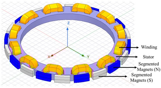
Figure 1.
Segmented structure of in-wheel BLDCM.
The segmented structure of permanent magnets in the axial direction is used to reduce the effect of eddy-current losses. The radial magnets on the rotor surface are divided into blocks isolated from each other in the axial direction. This division structure converts the eddy-current paths into smaller segments, as seen in Figure 2. When the eddy-current paths are divided into smaller loops by segmentation, the effective resistance increases. Since eddy currents are limited by resistance, the associated power loss is reduced [9,11].
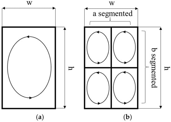
Figure 2.
Eddy-current path (a) for monolithic PM (b) for segmented PM.
A lumped representation of one eddy-current loop on a monolithic PM with a horizontal length of w and a vertical length of h is shown in Figure 2a. Figure 2b shows that the magnet is segmented into a and b segments horizontally and vertically, respectively. The segmentation constitutes nine eddy-current loops and indicates that the effect of eddy-current loss is diminished. If the induced voltage of the monolithic magnet loop is E, then for the segmented version, each PM segment has an E/ab-induced voltage and the path length of each loop is 2(w/a + h/b), as expected. Assuming that there is a magnet in Cartesian coordinates, for a constant magnetic field along the z-axis, the magnetic field of PM can be expressed as follows [29,30,31]:
where μ is the magnet permeability, σ is the magnet conductivity, ω is the angular frequency of the harmonic magnetic field, and Hz is the magnetic field strength in the z-axis direction.
For a non-segmented magnet, the eddy-current loss is derived as shown below [29,30,31]:
where K is the constant, depending on the material and structural features; Ra is the reluctance of the horizontal direction; and Rb is the reluctance of the vertical direction. After the axial PM segmentation, the eddy-current loss expression becomes [29,30,31]
where N is the number of axial segmentations. The segmented and non-segmented energy-loss ratio is related to the main dimensions and level of segmentation, as shown in Equation (6) [29,30,31].
where Wseg is the segmented eddy-current loss energy and Wnonseg is that of the non-segmented situation. E is the eddy-current electric field strength, a is the number of radial segmentations, and b is the number of axial segmentations, respectively.
In a more generalized approach, both axial and radial segmentations are considered. The ultimate aim of this study is to develop an equation that provides a useful computational approach for electric machine designers, such as
where RPM_seg is the reduction loss amount attributed to PM segmentation and SA and SR are the nonlinear coefficients for axial and radial segmentation which depend on machine dimensions and machine topology, consecutively. NA and NR are the numbers of axial and radial segmentations, respectively. Due to the complex nature of PM eddy-currents, determining the coefficients requires both theoretical and empirical approaches. Radial PM segmentation, especially for high-speed motors, requires further investigation due to end effects resulting from rotational motion.
3. Electromagnetic Analysis of In-Wheel PMSM
The electric motor that is the subject of this study is an outer rotor PMSM that is designed especially for direct-drive LEV propulsion. As we know, LEVs are frequently used in methods of urban and personal transportation such as e-bikes, e-scooters and small cars. Outer rotor electric motors are preferred in direct-drive LEV propulsion with single- or multi-motor power trains. The exploded assembly of the in-wheel motor that is the subject of this study is shown in Figure 3.
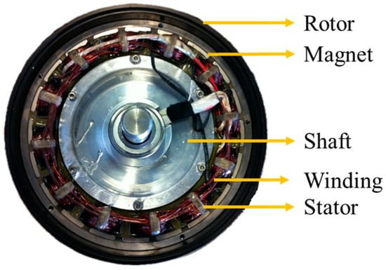
Figure 3.
Studied in-wheel (hub-type) PMSM.
The design parameter goals of the motor are listed in Table 1. As higher speed is not the concern, i.e., a field-weakening operation is not necessary, a three-phase, surface-mounted PMSM with a 24-slot/20-pole stator–rotor combination is preferred. The motor is a relative of the much-celebrated sub-fractional concentrated winding 12-slot/10-pole PM motor, which has an exceptional torque production capability and is suitable for both trapezoidal and sinusoidal control [32]. By considering the target vehicle speed and rotor radius, a 20-pole configuration is found to be suitable based on the previous literature [33]. Also, the basic power density values of PMSMs are used to define the motor power for the available motor space. Consequently, an electromagnetic analysis is conducted to obtain the basic performance parameters of the motor as shown in Table 2.

Table 1.
Design parameters of in-wheel PMSM.
Table 2.
Performance parameters of in-wheel PMSM.
In Table 2, it is shown that the targeted values are in agreement with the results of the analysis; however, there is still a need for experimental verification. In this phase of the study, ANSYS Electronics Desktop 2022 R2 software, specifically its Maxwell 3D module, is used to investigate the design modifications. FEA shows that the magnetic flux distribution is appropriate and the flux density values do not exceed the limits of the selected core material except for a few small spots, i.e., stator tooth edges, as expected. Figure 4 shows an electromagnetic analysis of the motor. The flux density reaches a value of approximately 2.4 T in the tooth edges, which implies the beginning of saturation.
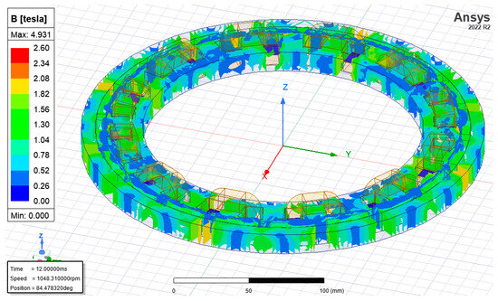
Figure 4.
Distribution of flux density in 3D analysis of monolithic magnet motor.
After the conventional design analysis, the implementation of segmented PMs, which is the main concern of this study, is taken into account. The main aim is to investigate the torque improvement of the PMSM with axially segmented PMs. Of course, a similar study with radially segmented PMs can be conducted. Also, the proportion of PM eddy-current loss in total losses will be examined. As mentioned before, the segmentation of PMs results in a reduction in motor losses and it is foreseen that an improvement in motor torque will be achieved. The motor with radially assembled and axially segmented PMs is shown in Figure 5. The back iron of the motor is removed to better understand the motor structure in the figure.
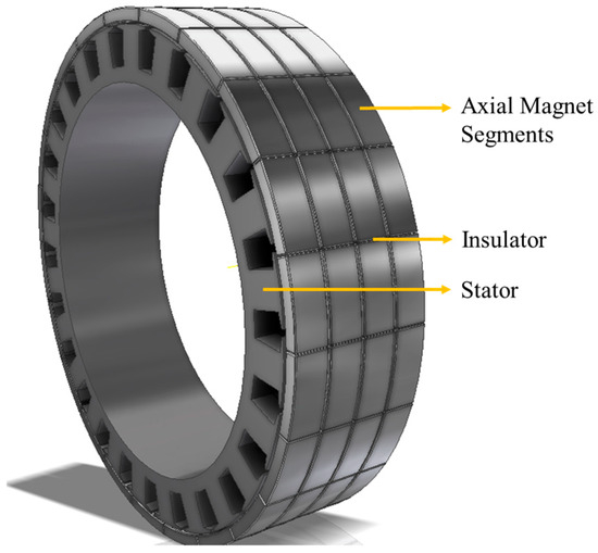
Figure 5.
Radial flux PMSM with PMs segmented axially.
An initial analysis is conducted to test the validity of the thesis of PM segmentation. A non-segmented PM motor is compared with the motor with two PM segmentations. The results of the analysis are given in Table 3. Even for this small number of PM segmentations, the motor torque increases by a substantial amount, i.e., approximately 1.2%, and there is a slight improvement in motor efficiency at a similar rate.
Table 3.
Effect of segmented magnets on in-wheel radial flux PMSM.
A 3D electromagnetic analysis of the PMSM with two PM segmentations is shown in Figure 6. The analysis concludes that the slight decrease in flux density relieves the motor performance.
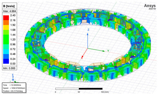
Figure 6.
Electromagnetic analysis of PMSM with 2 axial PM segmentations.
The results given in Table 3 imply that the segmentation of PMs has a positive effect on the performance of the motor by improving efficiency and torque and reducing total losses. For both designs, the flux densities in the stator tooth edges are higher, but do not affect the performance substantially. The main objective of electromagnetic design is to prevent magnetic saturation, which reduces the magnetic quality of the ferromagnetic core of the motor.
4. Optimization Study
Although the main aim is to improve the motor performance by PM segmentation through reducing the PM eddy-current loss, obviously, there is a physical limit to the segmentation process. Multiple analyses were conducted by increasing the number of PM segmentations to search for an optimal design. Thus, the number of segmentations increased from 2 to 10 during the analysis. It was expected that the reduction in PM eddy-current losses would lead to performance optimization, as implied in Equation (3). Another expected outcome was a decrease in heating due to lower eddy currents, resulting in a direct improvement in the operational performance of PMs. The results of the analyses used to identify the optimum design are given in Table 4. For a fixed motor speed, the motor torque and efficiency became better as the level of segmentation was increased. The decision about the maximum number of segmentations is mostly based on the feasibility of manufacturing. Dealing with smaller PM segments is easier, but at some point, it can be difficult to divide and assemble PMs due to the mechanical limitations of PM production. The cogging torque which is related to the slot–pole combination and stator tooth structure remains unchanged due to its independence from PM segmentation, as anticipated. As the level of PM segmentation rises, the torque increases from 29.1484 Nm to 30.65 Nm, implying a 5.1% positive change. The efficiency also reaches up to 98.29%, showing a substantial increase.
Table 4.
Optimization of segmented magnets.
In Figure 7, the torque and output power improvement by the PM segmentation are shown graphically.
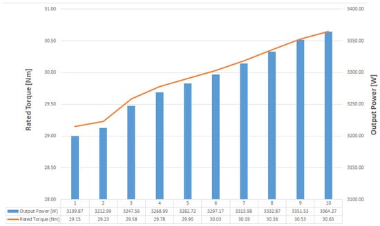
Figure 7.
Change in motor torque and output power by axial PM segmentation.
5. Essential Dimensions of In-Wheel BLDCM
After thorough analyses and simulations, the designed PMSM is manufactured. For experimental comparison, two different magnet assemblies with monolithic and two-segment PMs are fabricated. The experimental work is conducted by changing two magnet assemblies and back-irons, i.e., the outer rotor, using a single stator structure. The two different outer rotors are presented in Figure 8, where the monolithic and two-segment PMs can be seen explicitly.
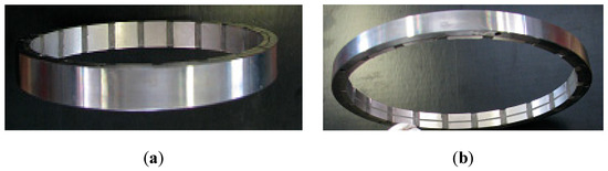
Figure 8.
Two different outer rotors: (a) with monolithic or single-segment PMs; (b) with 2-axial segment PMs.
A half-assembled prototype motor is seen in Figure 9. Firstly, the motor with monolithic PMs is assembled and placed on the test setup consisting of an eddy-current brake loader, i.e., a magnetic load and a precise torque transducer. A dummy shaft which is connected to the outer rotor is used to couple the motor to the load through the torque measurement device.
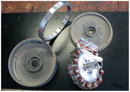
Figure 9.
Prototype of the in-wheel PMSM.
The test bench is seen in Figure 10. During the experiments, the ambient temperature was kept constant between 21–22 °C by a controlled HVAC system. The motor is operated by an industrial sinusoidal drive. The loading mechanism is an eddy current brake system adjusted by a variable air-gap PM assembly and an aluminum disc. The system operates with relatively acceptable precision due to its mechanical limitations. All electrical and mechanical measurements were obtained using high-precision measuring devices. The prototyped PMSM was driven by a microcontroller implementing sinusoidal control. All electrical and mechanical noises were snubbed using special filters and components. The DC-link voltage, DC-link current, RMS motor terminal currents, motor speed, output torque, and input power were measured and the rest of the related performance values were calculated.
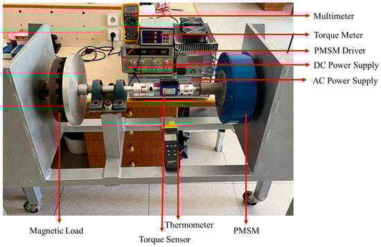
Figure 10.
Test setup.
The experimental results for the motor with monolithic PMs are presented in Table 5. The outer rotor of the motor was replaced by the two-segment PMs version and all loading schemes and measurements were conducted again. The related test results for the motor with two-segment PMs are given in Table 6. Due to some differences in the available materials and manufacturing tolerances, the air-gap flux was slightly higher than the value calculated in the analysis, resulting in marginally higher actual torque and lower speed for the given output power.
Table 5.
Monolithic magnet motor performance test results.
Table 6.
Motor with 2-segment PM performance test results.
To visualize the comparison, the motor efficiency versus speed variation is given in Figure 11 for both motors. The improvement in output torque, efficiency, and MTPA for the two-segment PMs is obvious. The experimental study also verifies the previous design analyses. The torque is increased by 1.2% compared to the motor with monolithic PMs, as calculated previously. Due to the availability of PMs and limitations in the manufacturing process, no further segmentation could be performed. But even in this case, the results are very promising.
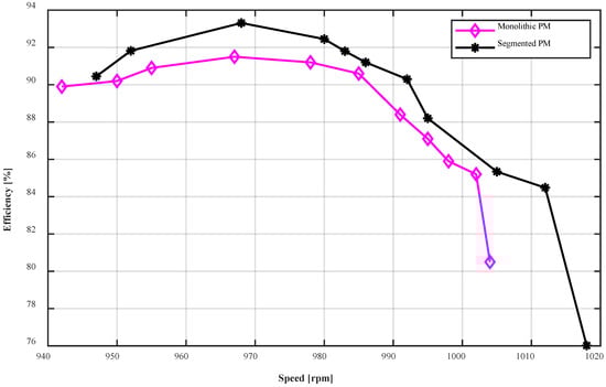
Figure 11.
Efficiency versus speed graphs of both motor protypes obtained experimentally.
Another important point is that motors used in electric vehicles are continuously operated at different speeds due to road conditions and driving preferences. It is also important to analyze the torque performances of the motors with different numbers of PM segmentations at a range of motor speeds. The results are given in Figure 12.
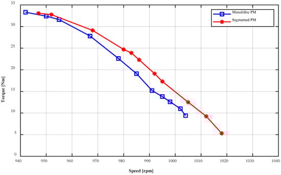
Figure 12.
Torque versus speed graphs of both motor protypes obtained experimentally.
As can be seen in Figure 12, there is an important difference between the two cases. The torque values of the two designs start to converge at lower speeds because of the reducing effect of eddy currents.
6. Conclusions and Future Aspects
In this study, the impact of eddy-current losses on the performance of PMSMs is investigated by means of analyses and experimental work. It is shown that axial PM segmentation enables torque and efficiency improvements in PMSMs. The conducted analyses and experimental study indicate the validity of the PM segmentation contribution. The theoretical calculations, as expected, reveal more optimistic views regarding the design. The study shows a torque improvement resulting from segmentation whilst the speed of the motor is kept unchanged. The rate of torque improvement is in the range of a few percent, but this improvement affects other performance parameters such as efficiency. For electric vehicles, even the slightest positive changes in efficiency and torque are essential due to the limited energy capacity of vehicle batteries. Basically, in-wheel motors used in LEVs are torque motors with large rotor diameters, i.e., higher torque and lower speed due to the nature of direct-drive applications. Thus, torque optimization becomes crucial. Increasing the relatively low efficiency of direct-drive motors caused by lower operation speeds is another essential target. Therefore, it is necessary to push design constraints, as attempted in this study. Our experimental study includes tests of motors with monolithic PMs and two-segment PMs. Naturally, PM segmentation has an upper limit due to manufacturing issues. On the other hand, PM segmentation brings flexibility and ease of assembly to PM rotor manufacturing. For example, an arc-type magnet can be formed by using smaller prismatic magnets to create radial segmentation. Due to these facts, some manufacturers are currently offering various segmented and electrically isolated PMs.
In conclusion, the presented study on PM segmentation reveals promising results and findings in terms of PMSM performance. To establish a concrete basis, this research includes theoretical calculations and an appropriate experimental study. Future studies will be conducted using different segmentation types and topologies. An important consideration is whether the direction of segmentation is radial or axial, and which method is the best based on the motor topology. The theoretical field of study will be further explored in the discussions to come. The examination of the effective PM air-gap area which is diminished by segmentation is another important aspect of future studies. It is necessary to determine the minimum useful distance between segmented magnet pieces, the optimum insulation material, the best machining method for segmentation, etc. In addition, the theoretical and practical limitations of segmentation will be investigated and validated. In future studies, a new test setup will be designed to obtain more precise experimental measurements.
Future work also includes determining the axial and radial segmentation coefficients. The preliminary calculations show that the nonlinear and intricate nature of the coefficients is a result of many dependent variables. Both theoretical and experimental studies will be carried out to reveal these. In high-speed motors, non-uniform distribution of eddy currents due to PM segmentation will be investigated in detail.
Author Contributions
Conceptualization, A.S.C. and O.U.; methodology, A.S.C. and O.U.; software, A.S.C.; validation, A.S.C. and O.U.; formal analysis, A.S.C. and O.U.; investigation, A.S.C. and O.U.; resources, A.S.C. and O.U.; data curation, A.S.C. and O.U.; writing—original draft preparation, A.S.C. and O.U.; writing—review and editing, A.S.C. and O.U.; visualization, A.S.C.; supervision, A.S.C.; project administration, A.S.C. All authors have read and agreed to the published version of the manuscript.
Funding
This research was supported by the Scientific and Technological Research Council of Turkey (TÜBİTAK) with Grant No: 121E131.
Data Availability Statement
The data obtained from this article may be shared upon request.
Conflicts of Interest
Author Ozgur Ustun was employed by the Mekatro Mechatronic Systems R&D Company. The remaining authors declare that the research was conducted in the absence of any commercial or financial relationships that could be construed as a potential conflict of interest.
References
- Shi, Z.; Sun, X.; Cai, Y.; Yang, Z.; Lei, G.; Guo, Y. Torque Analysis and Dynamic Performance Improvement of a PMSM for EVs by Skew Angle Optimization. Trans. Appl. Supercond. 2019, 29, 2882419. [Google Scholar] [CrossRef]
- Ou, C.-H.; Cheng, C.-C.; Chen, C.-Y.; Bhumkittipich, K.; Romphochai, S. Solving optimal electric vehicle charging station placement problem using digital quantum annealing. J. Commun. Netw. 2025, 27, 252–263. [Google Scholar] [CrossRef]
- Jinwen, Z.; Yumei, Q. Research on motor control of new energy electric vehicle. In Proceedings of the IEEE 3rd International Conference on Electronic Technology, Communication and Information (ICETCI), Changchun, China, 26 May 2023; pp. 637–640. [Google Scholar] [CrossRef]
- Cabuk, A.S.; Ustun, O. In Search of the Proper Dimensions of the Optimum In-Wheel Permanent Magnet Synchronous Motor Design. Energies 2024, 17, 1106. [Google Scholar] [CrossRef]
- Kovacik, M.; Rafajdus, P.; Bastovansky, R. Mechanical Analysis of Different Rotor Topologies for High Speed PMSM in Automotive Application. In Proceedings of the 2021 International Conference on Electrical Drives & Power Electronics (EDPE), Dubrovnik, Croatia, 22 September 2021; pp. 50–55. [Google Scholar] [CrossRef]
- Park, C.S.; Kim, J.H.; Park, S.H.; Lim, M.S. Effect of Electromagnetic Force Caused by PMSM on the Vibration/Noise of Reciprocating Compressors. IEEE Access 2023, 11, 56324–56335. [Google Scholar] [CrossRef]
- Fristedt, A.; Ullenhag, S. Development and Enhancement of electric vehicle Permanent Magnet Synchronous Motors (PMSM). Int. J. Adv. Electr. Eng. 2024, 5, 47–50. [Google Scholar]
- Yang, Y.; He, Q.; Fu, C.; Liao, S.; Tan, P. Efficiency improvement of permanent magnet synchronous motor for electric vehicles. Energy 2020, 213, 118859. [Google Scholar] [CrossRef]
- Guo, S.; Su, X.; Zhao, H. Optimal Design of an Interior Permanent Magnet Synchronous Motor for Electric Vehicle Applications Using a Machine Learning-Based Surrogate Model. Energies 2024, 17, 3864. [Google Scholar] [CrossRef]
- Tong, W.; Luo, H.; Cai, D.; Wu, S. Improved Accurate Subdomain Model for Magnetic Field Analysis of Surface-Mounted PMSMs with Modular Stator Cores Considering Tooth-tips Saturation Effect and Assembly Clearance. IEEE Trans. Energy Convers. 2025, 3603180. [Google Scholar] [CrossRef]
- Chen, J. Design of Spindle Permanent Magnet Synchronous Motor and Comparative Analysis of Different Core Materials. In Proceedings of the 5th International Conference on Intelligent Control, Measurement and Signal Processing (ICMSP), Chengdu, China, 19 May 2023; pp. 665–670. [Google Scholar] [CrossRef]
- Chen, W.; Yunpeng, L.; Dong, C.; Zhuoran, Z. PM Eddy-Current Loss Reduction of Axial Flux PM Wheel Motor with Arc Incompletion Segmentation. IEEE Trans. Magn. 2023, 59, 3288014. [Google Scholar] [CrossRef]
- Miljavec, D.; Zidaric, B. Eddy current losses in permanent magnets of the BLDC machine. Int. J. Comput. Math. Electr. Electron. Eng. 2007, 26, 1095–1104. [Google Scholar] [CrossRef]
- Tang, S.; Liu, W.; Zou, H.; Wang, P. Introduction to Rotor Eddy Current Loss of Permanent Magnet Motor for Electric Vehicles. In Proceedings of the Asia-Pacific Energy Equipment Engineering Research Conference (AP3ER 2015), Zhuhai, China, 13–14 June 2015; pp. 31–34. [Google Scholar]
- Steentjes, S.; Boehmer, S.; Hameyer, K. Permanent Magnet Eddy Current Losses in 2D FEM Simulations of Electrical Machines. IEEE Trans. Magn. 2015, 51, 2362551. [Google Scholar] [CrossRef]
- Yunpeng, L.; Chen, W.; Dong, C.; Guoyao, L.A. Simple PM Eddy Current Loss Model for Axial Flux Permanent Magnet Machine. In Proceedings of the IEEE International Magnetic Conference, Rio de Janeiro, Brazil, 5 May 2024; pp. 1–2. [Google Scholar] [CrossRef]
- Qu, X.; Xu, Z.; Yao, J.; Zhang, F. Electromagnetic Design and Analysis of High-Speed Permanent Magnet Motor with Composite Rotor. In Proceedings of the IEEE 6th International Electrical and Energy Conference (CIEEC), Hefei, China, 12 May 2023; pp. 2593–2597. [Google Scholar] [CrossRef]
- Sun, X.; Shi, Z.; Lei, G.; Guo, Y.; Zhu, J. Multi-Objective Design Optimization of an IPMSM Based on Multilevel Strategy. IEEE Trans. Ind. Electron. 2021, 68, 139–148. [Google Scholar] [CrossRef]
- Khan, O.; Acharya, S.; Al Hosani, M.; El Moursi, M.S. Hill climbing power flow algorithm for hybrid DC/AC microgrids. IEEE Trans. Power Electron. 2018, 33, 5532–5537. [Google Scholar] [CrossRef]
- Rezk, H.; Fathy, A. Simulation of global MPPT based on teaching–learning-based optimization technique for partially shaded PV system. Electr. Eng. 2017, 99, 847–859. [Google Scholar] [CrossRef]
- Samani, L.; Mirzaei, R. Maximum power point tracking for photovoltaic systems under partial shading conditions via modifed model predictive control. Electr. Eng. 2021, 103, 1923–1947. [Google Scholar] [CrossRef]
- Ma, S.; Hao, X.; Zhang, B.; Zhao, G. Model-Based Predictive Vibration Suppression Algorithm for Permanent Magnet Synchronous Motor. Energies 2025, 18, 4252. [Google Scholar] [CrossRef]
- Goh, J.W.; Xie, S.; Wang, H.; Zhu, S.; Yu, K.; Lee, C.H.T. Development of a Surface-Inset Permanent Magnet Motor for Enhanced Torque Density in Electric Mountain Bikes. Energies 2025, 18, 3709. [Google Scholar] [CrossRef]
- Wang, Y.; Ma, J.; Liu, C.; Lei, G.; Guo, Y.; Zhu, J. Reduction of Magnet Eddy Current Loss in PMSM by Using Partial Magnet Segment Method. IEEE Trans. Magn. 2019, 55, 2895887. [Google Scholar] [CrossRef]
- Chen, J. State-of-the-Art, Challenges, and Future Trends in Hub Motor Technology for New Energy Electric Vehicles. Sci. Technol. Eng. Chem. Environ. Prot. 2025, 1, 1–6. [Google Scholar] [CrossRef]
- Bertolini, T.; Fuchs, T. Vibrations and Noises in Small Electric Motors; Vogel Communications Group: Würzburg, Germany, 2012; pp. 22–98. [Google Scholar]
- Yan, J.; Yang, J.; Chen, J.; Zhang, C.; Qiu, S.; Liu, W. Unequal Teeth Width for Torque Optimization in PMSM with the Same Number of Poles and Slots. In Proceedings of the IEEE 8th International Electrical and Energy Conference (CIEEC), Changsha, China, 16 May 2025; pp. 1765–1770. [Google Scholar] [CrossRef]
- de Paula, G.T.; Monteiro, J.R.B.D.A.; de Alvarenga, B.P.; de Almeida, T.E.; Pereira, W.C.; de Santana, M.P. On-Load Back EMF of PMSM Using Maxwell Stress Tensor. IEEE Trans. Magn. 2018, 54, 2829692. [Google Scholar] [CrossRef]
- Hendershot, J.R.; Miller, T.J.E. Design of Brushless Permanent-Magnet Machines, 2nd ed.; Motor Design Books LLC: Venice, FL, USA, 2010. [Google Scholar]
- Yang, J.; Wu, R.; Wang, C. Effect of Permanent Magnet Segmentation Structure on Eddy Current Loss of Permanent Magnet Synchronous Motor. J. Phys. Conf. Series 2023, 2655, 012026. [Google Scholar] [CrossRef]
- Cabuk, A.S. Simulation of the effect of segmented axial direction magnets on the efficiency of in-wheel permanent magnet brushless DC motors used in light electric vehicles based on finite element method. Electr. Eng. 2021, 103, 3111–3117. [Google Scholar] [CrossRef]
- Cros, J.; Viarouge, P. Synthesis of High-performance PM motors with Concentrated Windings. EEE Trans. Energy Convers. 2002, 17, 248–253. [Google Scholar] [CrossRef]
- Salminen, P. Fractıonal Slot Permanent Magnet Synchronous Motors for Low-Speed Applications. Ph.D. Thesis, Lappeenranta University of Technology, Lappeenranta, Finland, 2004. [Google Scholar]
Disclaimer/Publisher’s Note: The statements, opinions and data contained in all publications are solely those of the individual author(s) and contributor(s) and not of MDPI and/or the editor(s). MDPI and/or the editor(s) disclaim responsibility for any injury to people or property resulting from any ideas, methods, instructions or products referred to in the content. |
© 2025 by the authors. Licensee MDPI, Basel, Switzerland. This article is an open access article distributed under the terms and conditions of the Creative Commons Attribution (CC BY) license (https://creativecommons.org/licenses/by/4.0/).