Abstract
With the increasing grid integration of wind turbines, mechanical reliability issues have become more critical. In particular, two-mass drivetrains undergo severe torsional vibrations due to abrupt torque fluctuations during low-voltage ride-through (LVRT) events. To address this, this paper proposes an adaptive damping coefficient determination method that differs from conventional pole-based approaches. The generator speed is decomposed into steady-state and transient components, and the maximum torsional angle is directly computed by integrating the transient component to derive the optimal damping coefficient. An adaptive algorithm adjusts this coefficient in real time according to operating conditions. The proposed approach is verified through PSCAD simulations of a 4.5 MW Type-4 permanent magnet synchronous generator (PMSG) wind turbine with a fully grid-decoupled back-to-back converter. Simulation cases combining active power levels (100% and 20%) with fault durations (20 ms and 400 ms) demonstrate that, compared with the conventional pole-based approach, applying the optimal damping coefficient reduces the maximum torsional angle by 30–37%, accelerates transient damping, and stabilizes speed and torque responses. The proposed method effectively mitigates drivetrain stress during LVRT, providing practical guidelines to enhance drivetrain reliability in Type-4 wind turbines.
1. Introduction
Wind energy has become a cornerstone of the renewable energy transition, with the grid integration of wind turbines increasing rapidly worldwide [,,]. Although large-scale integration improves grid flexibility and supports a higher share of renewables, it also raises significant mechanical reliability concerns for wind turbine drivetrains. In particular, repeated vibrations and cyclic loads in drivetrain components such as torsional shafts, gearboxes, and bearings can cause structural damage, fatigue cracks, higher maintenance costs, and unexpected downtime. These mechanical issues critically affect turbine lifetime and operational costs, underscoring the need for control strategies to enhance drivetrain reliability [,]. During low-voltage ride-through (LVRT) events, transient torque fluctuations induced by torsional vibrations are identified as a primary cause of gearbox and generator damage, accounting for approximately 57% of total drivetrain failures []. Furthermore, reports from the National Renewable Energy Laboratory (NREL) indicate that such drivetrain component failures are a major contributor to the increased operation and maintenance (O&M) costs of wind power systems and significantly elevate the levelized cost of energy (LCOE) []. These statistical observations highlight that suppressing torsional vibrations under LVRT conditions is a critical requirement for enhancing the mechanical reliability of wind turbines.
Wind turbine drivetrains are typically modeled as two-mass systems, which inherently exhibit torsional resonance. These resonances correspond to the natural frequencies of the two-mass system due to the inertia of the blade side and the generator side and the elastic properties of the shaft and can be greatly stimulated by external disturbances or torque changes. In particular, under low-voltage ride-through (LVRT) events, the rapid drop and recovery of grid voltage induce abrupt variations in generator electromagnetic torque, which in turn cause strong shaft torque fluctuations that can significantly amplify torsional oscillations [,]. Such oscillation amplification accelerates structural fatigue and may result in shaft failure as well as additional stress issues caused by the relative motion between the generator and blades. Therefore, understanding and mitigating shaft torsional oscillations under LVRT conditions is essential to ensuring the reliability and stability of wind turbines.
Conventional approaches commonly apply a band-pass filter to the generator speed response to extract the torsional component and then multiply it by a fixed damping coefficient to generate active damping torque. In this approach, the damping coefficient is typically obtained by isolating the torsional mode of the two-mass drivetrain, approximating it as a standard second-order system, and assigning a target damping ratio [,,].
Alternative approaches have been proposed, including robust control schemes based on H∞ observers and controllers that estimate shaft torsional torque or speed for feedback to the velocity loop [], nonlinear control strategies employing virtual synchronous machine (VSM) concepts [], and model predictive control (MPC)-based optimization frameworks designed to enhance drivetrain dynamic performance []. However, these methods typically require complex system modeling, real-time optimization computations, and sensor-based state estimators, making direct implementation in field controllers impractical. In contrast, the BPF-based damping technique can be realized by simply adding a minor compensating path to the existing controller structure. It offers low computational complexity while providing sufficient damping effectiveness, making it a widely adopted and practical solution in real-world applications. However, such methods face a fundamental limitation: they cannot accurately predict the maximum torsional angle under step-like torque variations encountered during LVRT. In particular, because the phase delay and zero dynamics of the band-pass filter are not fully accounted for during the transient response, the simulations conducted in this study also confirm that the shaft torsional-angle response can be overestimated or underestimated by approximately 10–20% relative to the actual torque amplitude. Such estimation errors hinder accurate assessment of damping performance under LVRT conditions and consequently impair the effectiveness of vibration suppression.
This paper proposes a new damping torque compensation method to overcome these limitations. Specifically, a time-domain analysis is performed to separate the transient component of the generator speed response, and an integral-based model is developed to predict the maximum torsional angle. Although the structure resembles conventional damping approaches, the proposed method strengthens their practicality by explicitly providing an optimization framework for the damping coefficient. The torsional response is systematically analyzed under varying torque and damping conditions, from which an optimal damping design is derived to balance vibration suppression and dynamic performance. Furthermore, this study proposes a damping algorithm specifically tailored for LVRT conditions—an aspect relatively overlooked in previous research. By adaptively adjusting the damping gain at the onset of voltage sag, the proposed method effectively suppresses the overshoot in torsional response, reduces the maximum torsional angle, and mitigates opposite-phase torsional motion. Consequently, it alleviates the cumulative fatigue load on the shaft, prevents mechanical damage induced by transient torque fluctuations, and ultimately enhances the operational stability and component durability of wind turbine systems, leading to reduced operation and maintenance costs. The proposed method is applicable to multi-megawatt turbines, and its feasibility is demonstrated through simulations on a 4.5-MW Type-4 wind turbine model.
The remainder of this paper is organized as follows. Section 2 presents the two-mass drivetrain model and the Type-4 electrical system and formulates the torsional problem under LVRT. Section 3 analyzes the limitations of conventional damping approaches and introduces the proposed damping coefficient design. Section 4 describes the PSCAD-based simulation setup and validates the method under four scenarios combining pre-fault active power and LVRT duration. Finally, Section 5 concludes the paper with a summary of key findings and a discussion of future research directions.
2. System Modeling of Wind Turbine and LVRT Conditions
2.1. Two-Mass Drivetrain Modeling
The drivetrain of a wind turbine comprises the blade assembly and the generator, which are coupled through a single shaft. Each mass possesses a distinct moment of inertia, while the connecting shaft exhibits linear elastic behavior. Furthermore, the blade, generator, and shaft are associated with individual damping coefficients that account for frictional losses. Considering these damping effects, the torque equilibrium for both the blade and generator sides can be expressed as follows.
In Equation (1), represents the blade-side inertia, the generator-side inertia, the shaft torsional stiffness coefficient, the blade torque, the generator torque, and the angular velocities of the blade and generator, the relative angular displacement between them, and their respective angular accelerations, and the viscous damping coefficients of each mass, and the torsional damping coefficient of the shaft.
As the purpose of this study is to analyze the worst-case torsional vibration response under LVRT conditions, the viscous damping terms () and the torsional damping term () are neglected in the analytical derivation and transfer function formulation. Although these terms physically exist, they act to suppress oscillations; thus, their omission enables a conservative analysis and simplifies mathematical treatment. This simplification allows verification of the proposed damping strategy under conditions where the natural damping effect is minimized. Therefore, the fundamental two-mass dynamic model employed in this study is expressed as follows.
Accordingly, based on Equation (2), the drivetrain is modeled as a two-mass system, as depicted in Figure 1 [,].
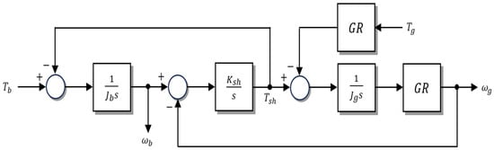
Figure 1.
Two-mass system block diagram.
The blade-side and generator-side torques act in opposite directions, inducing torsional deformation in the shaft. Even when the same magnitude of torque is applied to both masses, the difference in inertia causes the generator side to exhibit a relatively larger torsional displacement than the blade side. In addition, torsional oscillations may occur in the shaft within certain resonance frequency ranges, and thus an appropriate damping compensation component is required for suppression.
As shown in Figure 1, represents the shaft torque, while denotes the gearbox ratio.
2.2. Electrical Modeling and Control Structure of Type-4 Wind Turbine
The Type-4 wind turbine is based on a permanent magnet synchronous generator (PMSG) and full power converters, providing a configuration that is fully decoupled from the grid. The mechanical output is entirely transferred to the grid through the power converters, and the Type-4 configuration considered in this study consists of a back-to-back converter and a DC-link capacitor, which acts as an energy storage element to buffer power imbalance between the machine side and the grid side, as illustrated in Figure 2.
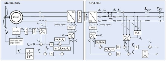
Figure 2.
Configuration of Electrical and Control System in Type-4 PMSG Wind Turbine.
In addition, the overall control system consists of a pitch controller, a generator-side controller, and a grid-side controller. The generator-side controller adopts a multi-loop structure with an inner current control loop and an outer torque control loop, thereby regulating the generator current vector to produce the desired electromagnetic torque. The reference current of the machine-side converter (MSC) is determined by dividing the commanded torque by the torque constant , as expressed below.
The -axis stator voltage equations of the permanent magnet synchronous generator (PMSG) can be expressed as follows.
Here, and denote the -axis stator voltages, and the corresponding stator currents, the stator resistance, and the -axis stator inductances, the permanent magnet flux linkage, and the electrical angular speed. Assuming that feedforward compensation is applied for the cross-coupling and back electromotive force (EMF) components in the voltage equations, the stator circuit can be simplified to an network. Accordingly, the equivalent resistance and inductance for tuning the synchronous reference frame current controller are given by and , respectively. Thus, the proportional–integral (PI) current controller gains for the synchronous reference frame current regulation can be determined as follows.
When the proportional and integral gains are determined as in Equation (5), the relationship between the actual current and its reference can be derived from the stator voltage equations. Under these conditions, the load pole and the controller zero effectively cancel each other, resulting in the actual current being represented as the reference current filtered through a first-order low-pass function, as expressed below.
Consequently, the inverter output current can be regulated without exhibiting any overshoot.
Similarly, the grid-side controller consists of an inner current control loop and an outer DC-link voltage control loop, through which the DC-link voltage is maintained constant and the power delivery to the grid is stabilized. Furthermore, under LVRT conditions, the machine-side converter (MSC) and grid-side converter (GSC) interact through the DC link but remain completely decoupled in control, operating independently. The MSC generates a -axis current in response to rapid variations in generator torque or the application of damping torque. During a voltage sag, however, the GSC cannot transfer power to the external grid due to the reduced grid voltage, resulting in the energy from the MSC being accumulated in the DC-link capacitor and causing its voltage to rise. To prevent overvoltage and ensure system stability, the DC-link chopper circuit is activated to dissipate the excess stored energy through a braking resistor.
In the low wind speed region, a Maximum Power Point Tracking (MPPT) control strategy is employed to regulate the generator torque in proportion to the square of the rotor speed, enabling maximum energy extraction from the available wind power.
Accordingly, the maximum power output of the wind turbine can be expressed as a cubic function of the rotor angular speed (), as given below.
Here, denotes the mechanical output power of the wind turbine, the air density, the rotor swept area, the maximum power coefficient, the low-speed shaft rotational speed, the blade radius, and the optimal tip-speed ratio.
In the high wind speed region, when the generator output reaches its rated value and the rotor speed can no longer increase, the pitch controller adjusts the blade pitch angle () to maintain the output below the rated power. The pitch controller operates based on rotor speed feedback and determines the appropriate pitch angle using a proportional–integral (PI) control scheme. Because both the MPPT and pitch control loops are speed-feedback systems, torsional resonance in the drivetrain can introduce oscillatory components into the speed signal. These resonant fluctuations propagate into the MPPT and pitch controllers, affecting their torque and pitch outputs, which can in turn reinforce the resonance, thereby deteriorating the overall system stability [,,].
2.3. Mechanical-Electrical Coupling for Damping Analysis
By integrating the aforementioned mechanical and electrical models, the influence of generator torque variations on the dynamic behavior of the shaft torsional angle can be formulated as follows.
Here, denotes the equivalent inertia. The blade-side torque varies over time with changes in wind speed and pitch angle, whereas the generator-side torque , produced by the generator control loop, varies according to the current controller dynamics and torque reference variation. The torque imbalance between the two () acts as a net disturbance torque on the shaft, exciting torsional oscillations. Accordingly, the proposed damping method detects the oscillatory component from the generator speed response and injects a corresponding compensating torque into the generator-side control loop to actively attenuate torsional vibration. Moreover, the electrical control loop operates at a much higher bandwidth than the mechanical system. Typically, generator-side current control bandwidth of 200–400 Hz represents a typical design range for MW-class Type-4 converters, determined primarily by the switching and sampling frequencies. The PSCAD Type-4B model employed in this study exhibits the same bandwidth characteristics. Because this electrical bandwidth is more than an order of magnitude higher than that of the mechanical drivetrain—whose shaft resonance typically lies below 10–20 Hz—the electrical and mechanical dynamics can be considered effectively decoupled.
From the perspective of the mechanical system, the transfer function of the electrical controller can be approximated as having nearly unit gain, meaning that the torque reference is almost instantaneously reflected in the generator torque. This approximation is valid under normal operating conditions in which no current limiting or converter saturation occurs; however, under extreme conditions such as LVRT, these nonlinear effects may introduce some deviations. Nevertheless, for the purposes of this study—namely, estimating the maximum torsional angle and designing the damping coefficient, this approximation provides sufficient accuracy. In essence, the electrical control loop introduces no significant delay to the torsional dynamics and provides a sufficiently fast control basis to inject or withdraw damping torque in real time. As a result, the proposed damping strategy is developed under the idealized condition that mechanical torque disturbances are almost instantaneously compensated by the electrical control loop, enabling accurate interpretation of torsional dynamics under coupled electromechanical behavior.
2.4. LVRT Operating Principles and Conditions
When fault events such as short circuits, lightning strikes, or large-scale load switching occur in the power system, the grid voltage momentarily drops sharply or enters an unbalanced condition. The representative grid phenomena that occur at this time can be summarized as voltage sags, voltage unbalance, delayed voltage recovery after fault clearance, and current surges. These phenomena can seriously affect both the protection of wind turbine power converters and the mechanical reliability of the drivetrain, and during the rapid drop and recovery of grid voltage, the generator electromagnetic torque changes abruptly, which induces strong shaft torque fluctuations and can greatly amplify torsional oscillations [,,].
As grid-connected resources, wind turbines are required to remain connected for a specified duration even during transient voltage sags or unbalances. This requirement, known as low-voltage ride-through (LVRT), has been codified by most grid operators and incorporated into interconnection standards. For instance, IEEE Std 2800-2022 specifies LVRT requirements for inverter-based resources using a voltage-time profile, as shown in Figure 3, and mandates the minimum duration that generators must remain connected under prescribed positive-sequence voltage sag levels. In other words, under these requirements, a turbine must withstand a terminal voltage drop to 10% of its nominal value for approximately 160 ms without disconnecting. While the detailed curves differ across countries and operators, a common requirement is that turbines must not trip immediately under deep voltage sags but should remain connected for a defined period before recovery [,].
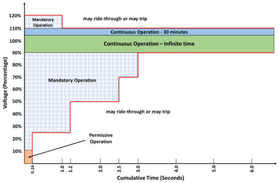
Figure 3.
Voltage ride-through requirements.
The LVRT requirement extends beyond a mere grid-connection condition, imposing direct constraints on the mechanical and electrical subsystem design of wind turbines. During a voltage sag, the power transferred to the grid drops sharply, causing an energy imbalance in the DC link. To control this imbalance, the generator current must be rapidly regulated, which in turn induces large transient variations in the electromagnetic torque. These torque transients interact with the drivetrain’s inherent vibration modes—particularly the torsional mode—resulting in a sharp rise in shaft stress and torsional deflection. Hence, LVRT events represent a complex disturbance scenario that simultaneously challenges grid stability from an electrical standpoint and drivetrain reliability from a mechanical standpoint. Accordingly, drivetrain damping design that accounts for LVRT behavior is indispensable, and this study proposes an optimal damping coefficient determination method within this context.
To fulfill LVRT requirements, the wind turbine controller must coordinate both electrical and mechanical control loops in an integrated fashion. The electrical control system stabilizes the DC-link voltage and provides rapid reactive current injection during voltage sags to assist in grid voltage recovery. Meanwhile, the mechanical control system mitigates drivetrain stress by suppressing torque transients or, in the case of prolonged voltage dips, by increasing the blade pitch angle to reduce mechanical input and prevent overloading. Therefore, LVRT operation constitutes a coupled electro-mechanical phenomenon involving both current injection and DC-link protection on the electrical side, and torque and pitch compensation on the mechanical side. This combined operating scenario defines the realistic condition under which the proposed damping design approach is validated in this study [,,,,].
3. Adaptive Damping Strategy During LVRT
In Section 2, the drivetrain of the wind turbine was modeled as a two-mass system, and the electrical control system of the Type-4 configuration as well as the LVRT operating conditions were examined. Based on this analysis, it was observed that under LVRT conditions, the voltage sag in the grid caused a rapid variation in generator torque, which in turn led to noticeable torsional vibrations in the drivetrain. Accordingly, this section formulates the problem and introduces a control strategy designed to effectively mitigate torsional mode resonance.
3.1. Limitations of Conventional Damping Approaches
In previous studies, methods utilizing the generator speed have been mainly proposed to suppress torsional oscillations occurring in the two-mass model [,,].
As illustrated in Figure 4, the conventional approach applies a band-pass filter (BPF) to the generator speed to extract the torsional mode frequency component, which is then multiplied by a damping coefficient () to produce the active damping torque (). The damping torque is then defined as:
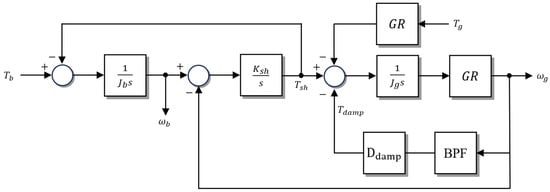
Figure 4.
Two-Mass System Block Diagram Including Compensated Damping Component.
Furthermore, from Figure 4, the torque balance equations for each mass are derived as follows.
From Equation (10), the transfer function relating the generator angular speed to the generator torque is obtained as follows.
Substituting the parameter values into Equation (11) allows the constant denominator term () to be neglected, yielding the following expression after factoring the s-terms.
Omitting the zero from Equation (12), the transfer function of the generator angular speed is obtained as follows.
Therefore, matching the denominator of Equation (13) to the standard second-order form yields the following relationship.
That is, according to Equation (14), by setting the desired torsional damping ratio , the corresponding damping coefficient can be calculated. In previous studies, values of have mainly been used, and such a range of damping coefficients is generally applied in MW-scale wind turbine drivetrains [,]. However, this approach suffers from inherent limitations.
The conventional method determines the damping coefficient by assuming steady-state operation, neglecting the zero in the original transfer function of Equation (12), and matching only the poles to a standard second-order system. As illustrated in Figure 5d, under a ramp torque input emulating steady-state operation, the generator speed responses are nearly identical regardless of the inclusion of the zero. This confirms that the zero has negligible influence during steady-state operation. Thus, selecting the damping coefficient from the simplified transfer function of Equation (13) without the zero is justifiable.
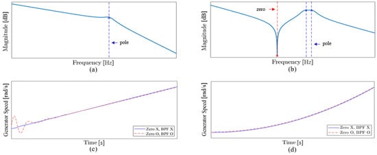
Figure 5.
Example Frequency- and time-domain comparison of the models without and with the zero/BPF: (a) Bode plot of Equation (13); (b) Bode plot of Equation (17); (c) generator-speed response to a step torque (LVRT simulation); (d) generator-speed response to a ramp torque (normal-operation simulation).
On the other hand, under transient conditions such as LVRT, as shown in Figure 5c, overshoot occurs depending on whether the zero is considered.
The conventional method of defining the damping coefficient by considering only the poles of the transfer function may be effective in suppressing resonance under steady-state conditions, but it has limitations in accurately predicting or ensuring suppression of actual shaft torsional oscillations under situations with abrupt torque variations such as LVRT.
Furthermore, previous studies did not consider the transfer function of the BPF used to extract a specific frequency band from the generator speed. The transfer function of the band-pass filter (BPF) is expressed as follows.
Considering the band-pass filter transfer function defined in Equation (15), two closely spaced poles become separated—a phenomenon known as pole-splitting—as illustrated in Figure 5b. This results in distinct damping ratios and oscillation frequencies, representing the inherent torsional vibration modes of the drivetrain.
The migration of these poles directly influences shaft stability and mechanical stress distribution. In particular, insufficient damping or the movement of poles toward the imaginary axis leads to increased torsional angle overshoot during torque transients, causing accumulated cyclic stress and potential fatigue damage to gears and shafts.
Therefore, under transient conditions such as LVRT, the damping coefficient must be redesigned by incorporating both the band-pass filter (BPF) characteristics and the effects of transmission zeros in the control path. To address this, the present study introduces a new damping coefficient determination approach that constrains the maximum torsional angle of the transient response based on the complete transfer function, including both the zeros and the BPF dynamics.
In summary, the conventional pole-based damping coefficient estimation is effective for resonance suppression under steady-state operation but lacks accuracy under rapidly varying torque conditions, such as LVRT, due to neglecting the BPF phase delay and zero dynamics. This limitation forms the basis for the proposed methodology, which maintains the structural simplicity and practical applicability of conventional methods while simultaneously accounting for pole migration and damping characteristics during transient events. The proposed framework effectively bridges the gap between mathematical idealization and the actual electromechanical behavior of the drivetrain, providing a quantitative design guideline for enhancing mechanical reliability.
Figure 5 illustrates the Bode plots of Equation (13), excluding the zero and BPF transfer function, and Equation (17), including them, along with a comparison of the generator speed responses to a step torque input representing the transient state and a ramp torque input representing steady-state operation. The presented waveforms are illustrative examples, and similar trends are typically observed in MW-scale wind turbines.
3.2. Derivation of Transient Torsional Response for Damping Coefficient Design
The core idea of the proposed approach is to directly compute the maximum shaft torsional angle corresponding to the input torque, given specific parameters and a damping coefficient. To this end, by incorporating the transfer function of the band-pass filter into the transfer function of the generator angular speed with respect to the generator torque defined in Equation (11),
and assuming a step torque as the generator input, the generator speed transfer function can be derived from the two expressions in Equation (16) as follows.
Deriving the time-domain response of the generator speed from this transfer function requires applying the inverse Laplace transform. Accordingly, the transfer function possesses a double pole at , while the remaining four poles form two pairs of complex conjugates, and it can thus be expressed via partial fraction expansion as follows.
The coefficients and obtained through the Taylor expansion are as follows.
For the partial fraction expansion of the poles other than the double pole, the poles of each partial fraction must first be derived. The quartic denominator equation can be solved using the standard Ferrari formula, yielding two pairs of complex conjugate poles as expressed in Equation (20) []. The detailed derivation process for this is provided in Appendix A.
Here, and denote the damping ratio and natural frequency of the high-frequency (fast mode) torsional vibration, corresponding to the elastic deformation of the generator shaft and mechanical coupling components. Conversely, and represent the damping ratio and natural frequency of the low-frequency (slow mode) torsional vibration, which arises from the energy exchange between the blade and generator inertias and manifests as a slower torsional response. Typically, and ; the high-frequency mode contributes to the suppression of transient torsional oscillations through rapid damping, whereas the low-frequency mode tends to sustain residual oscillations over a longer duration. Hence, controlling the damping ratios and amplitudes of both modes is crucial for mitigating shaft fatigue and maintaining dynamic stability of the drivetrain. The residue coefficient for each pole is
are obtained, and the residue coefficients likewise form complex conjugate pairs.
Therefore, by performing the inverse Laplace transform based on these obtained variables, the time-domain response of the generator angular speed can be expressed as follows.
The time-domain response of the generator speed can be decomposed into steady-state and transient components, with the steady-state component expressed as follows.
The transient component is as follows.
The time-domain response of the generator angular speed, together with its steady-state component and transient component, is shown in Figure 6.
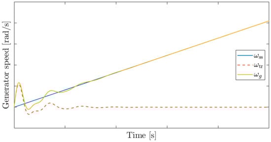
Figure 6.
Generator Speed Response with Steady-State and Transient Components in the Time Domain (example waveform under , more than 20 times).
Under step-like torque disturbances such as LVRT, when the blade inertia is much larger than the generator inertia (), the blade displacement remains nearly constant, and oscillations occur mainly on the generator side. Therefore, the steady-state component shown in Figure 6 corresponds to the blade angular speed (), while the transient component can be interpreted as the relative speed between the blade and the generator (). Thus, the shaft torsional angle is obtained by integrating the transient component, and evaluating this integral at the instant when the transient component first crosses zero yields the maximum torsional angle of the shaft under a step torque input.
The maximum torsional angle of the shaft, calculated as described above, serves as a key quantitative metric for determining the appropriate level of the damping coefficient . An excessively large torsional angle increases the cyclic stress amplitude on the shaft surface, accelerating fatigue accumulation. Conversely, applying an overly large damping coefficient over-suppresses the transient response, resulting in prolonged speed recovery and degraded dynamic performance. Accordingly, Section 3.3 derives the optimal damping coefficient for LVRT conditions based on the maximum torsional angle obtained from Equations (22)–(24), while Section 3.4 presents the implementation of an adaptive control structure that applies the coefficient in real time.
3.3. Derivation of Optimal Damping Coefficient Under LVRT Conditions
The rationale for selecting the damping coefficient within the range of 1000–2000 under steady-state operating conditions can be summarized in two main aspects. First, as shown in Figure 7, an excessively large damping coefficient may instead induce residual oscillations. Second, the band-pass filter used to extract the generator speed response cannot fully eliminate neighboring frequency components, regardless of its steepness. When the damping coefficient is excessively large, it undesirably suppresses the steady-state response within that frequency range. Therefore, under steady-state operating conditions where significant shaft torsional oscillations do not occur, it is desirable to apply a damping coefficient in the range of 1000–2000.
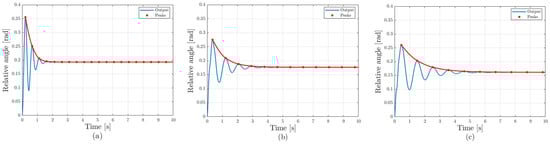
Figure 7.
Step Torque Response of the relative angle for different damping coefficients: (a) 1000, (b) 10,000, (c) 20,000.
To find the optimal damping coefficient used in the algorithm applicable when the generator input torque changes as a step, such as under LVRT conditions, the new analytical method described in Section 3.2 was applied to a 4.5 MW Type-4 wind turbine model with the parameters given in Table 1. Subsequently, the input torque was varied from 0 to 40,000 and the damping coefficient from 0 to 20,000, and the results of calculating the maximum torsional angle are shown in Figure 8a. The heatmap indicates that the maximum torsional angle is minimized at a damping coefficient of approximately 5200, after which it increases with further coefficient growth and then gradually decreases.

Table 1.
Mechanical Parameters and Rated Values of the 4.5 MW Type-4 Wind Turbine Model.
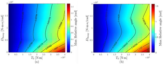
Figure 8.
Heatmap Analysis of Maximum Relative Angle: (a) Without Torque Limit, (b) With Torque Limit.
This behavior can be explained by the presence of two pairs of complex conjugate poles in the transient response of the generator speed, each associated with a distinct natural frequency.
Table 2 shows how the variables of Equation (22)—, (damping ratios), , (natural frequencies), and , (magnitudes)—change when the input torque is fixed and the damping coefficient is varied.
Table 2.
Effect of Damping Coefficient on Transient Response Modal Characteristics.
As the damping coefficient increases, the two natural frequencies separate, while the magnitudes remain similar. Furthermore, increasing the damping coefficient enhances the damping ratio of the higher-frequency mode while reducing that of the lower-frequency mode.
As seen in Figure 8, as the damping coefficient increases, the maximum torsional angle decreases, then increases again, and gradually decreases, while at the same time, as in Figure 7, the settling time becomes longer. Therefore, determining an optimal damping coefficient is essential to achieve a balanced trade-off between these two-performance metrics.
Figure 8a illustrates the trend of the maximum shaft torsional angle when the combined generator torque and damping torque, , is permitted to take negative values. However, in the simulation conditions of this study, must not become negative, so a constraint was imposed to prevent it from falling below zero. Without zero constraints, a negative would act in the blade acceleration direction. In addition, under LVRT conditions, it is difficult to deliver or draw power from the grid, and if becomes negative, DC-link energy is drawn, causing the DC-link to discharge. Therefore, when the constraint is applied, becomes zero, altering the system dynamics, and the generator speed response and maximum torsional relative angle also change.
That is, if a constraint is imposed to prevent from falling below zero, the entire time response cannot be represented by a single transfer function, and the solutions must be joined piecewise. When it is above zero, the system operates as a linear closed loop with the transfer function of Equation (17), and when it changes to below zero, and the system switches to open-loop operation. However, the open-loop equation cannot be applied in isolation; continuity must be enforced at the transition point where switches sign, ensuring a consistent generator speed response across intervals. Considering these conditions, the input torque was varied from 0 to 40,000 and the damping coefficient from 0 to 20,000. As shown in Figure 8b, the maximum torsional angle analysis revealed that the optimal damping coefficient was obtained at approximately 8500. When the damping coefficient was set within the range of 1000–2000, the maximum torsional angle was reduced by about 30–37% relative to that condition. Moreover, the same optimal value of 8500 was consistently identified across different output power levels and LVRT durations, demonstrating the robustness of the proposed method with respect to operating point variations. This consistency indicates that the optimal damping coefficient is primarily governed by the mechanical parameters of the system and is relatively insensitive to changes in operational conditions such as generator output or fault duration.
3.4. Proposed Adaptive Damping Implementation
During LVRT events, the generator torque undergoes rapid fluctuations, which significantly excite torsional vibrations within the drivetrain.
To effectively mitigate these oscillations, the optimal damping coefficient suitable for LVRT conditions was determined using the analytical approach introduced in Section 3.2 and Section 3.3. As illustrated in Figure 9, when the LVRT flag is activated, the damping coefficient transitions from its nominal value during normal operation () to the LVRT-optimized value (). To ensure continuity and prevent discontinuities resulting from this abrupt change, the BPF output of the generator speed is multiplied by a ratio at the rising edge of the LVRT flag.
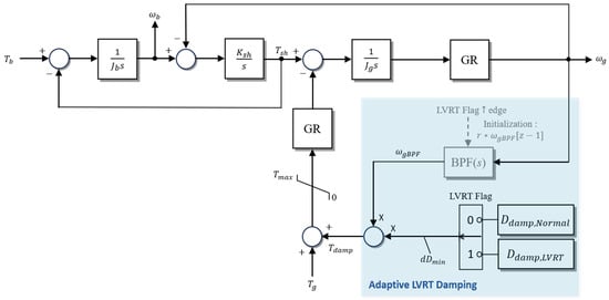
Figure 9.
Two-Mass System Block Diagram Including Adaptive LVRT Damping.
Once the LVRT condition is cleared, the generator current and torque gradually return to their steady-state operating points. Maintaining a high damping coefficient during this recovery phase can prolong the settling time, adversely affecting dynamic performance. Hence, in accordance with national grid code requirements, the damping coefficient is linearly decreased so that the active power recovery rate satisfies the prescribed time frame, eventually reverting to the nominal range of 1000–2000 commonly used in prior research.
The proposed adaptive damping coefficient is implemented in real time within the outer torque control loop of the generator-side controller. The generator speed signal passes through a band-pass filter (BPF) to isolate the torsional vibration component, which is then multiplied by the variable damping gain to generate the active damping torque (). This compensating torque is added to the generator torque reference and fed into the current control loop.
Because the compensation path is introduced without modifying the existing controller architecture, the proposed scheme can be implemented in real time without requiring additional high-speed processors or external control hardware.
In addition, when the LVRT flag is activated, the transition between and is completed within a single control cycle (on the order of several hundred microseconds), thereby introducing no noticeable delay in the overall control response. Furthermore, since the operating frequency of the proposed algorithm is significantly lower than the sampling rate of the current control loop (several kHz), simulation results confirm that even a delay of 1–2 samples (approximately a few hundred microseconds) does not have a meaningful impact on the torsional damping performance. If the LVRT duration becomes excessively long, the turbine transitions to the shutdown sequence regardless of the damping torque effect. During partial voltage recovery, the damping torque compensation remains active as long as the LVRT flag is asserted and is deactivated only once the LVRT flag is released.
4. Simulation Results and Discussions
4.1. Simulation Setup and Case Definitions
To validate the proposed method of this study, an LVRT scenario was simulated in the PSCAD environment. The simulation was configured in accordance with Figure 10, with reference to the Renewable Energy Technical Connection Code for Transmission Level published by KEPCO. The simulation incorporates the wind turbine’s mechanical model (two-mass system) and electrical model (Type-4 PMSG with back-to-back converter) detailed in Section 2 [].
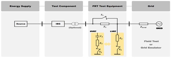
Figure 10.
LVRT Simulation Circuit Diagram [].
The simulation modeled a grid-connected wind turbine integrated into a 154 kV power system, with the grid represented as a Thevenin equivalent circuit comprising an ideal three-phase 154 kV voltage source and a series impedance. Subsequently, the internal impedance was configured so that the short-circuit ratio (SCR) between a single turbine and the point of common coupling (PCC) was approximately 54, with an X/R ratio of about 10. The fault was assumed to occur at the midpoint of the equivalent system impedance. In addition, to simulate grid voltage sag conditions, an LVRT test device capable of instantaneously reducing the voltage was inserted in the middle, and the overall simulation model was configured with a single wind turbine connected to the grid. The generator-side converter (GSC) employs a current control-based electromagnetic torque control loop with an inner current regulation loop, whereas the grid-side converter (GRC) incorporates DC-link voltage and reactive power control loops. The PI gains for all control loops were adopted from the default parameters of the PSCAD Type-4 (U151) reference model. During LVRT events, the torque reference is dynamically adjusted to prioritize reactive current injection in accordance with grid support requirements. To stabilize the neutral-point potential and mitigate harmonic distortion, a Zig-Zag transformer was implemented, ensuring balanced three-phase currents even under asymmetrical fault conditions. The LVRT flag was configured to be triggered when the active power level dropped below 0.9 pu.
The voltage sag event was configured such that the fault-point voltage instantaneously dropped to 0.1 pu and was maintained for 20 ms and 400 ms, and the key parameters used in the simulation are summarized in Table 1.
To comprehensively verify the effect of the proposed adaptive damping power, several simulation cases were configured. Case 0 was configured to examine the electrical output response under LVRT conditions. Subsequently, Cases 1 to 4 were configured by varying the LVRT duration and the turbine active power immediately before the fault, and these are summarized in Table 3.
Table 3.
Simulation cases.
In each case, different damping coefficients were applied to analyze the turbine’s mechanical dynamics—active power, relative angle, and angular speed—thereby evaluating how the effectiveness of the proposed method is influenced by LVRT duration and the turbine operating point.
4.2. Case 0: Electrical Output Response During LVRT
Case 0 is a condition for checking the electrical output response of the wind power generation system when an LVRT event occurs. In this case, LVRT was set as a situation where the terminal voltage rapidly drops to 0.1 pu of its rated value and is sustained for about 400 ms. In this case, neither damping coefficient variation nor additional control strategies were applied; the system was operated only with the basic controller, and the damping coefficient was set to 1500 to observe the system response.
The lower waveform of Figure 11 shows the grid-side converter (GSC) current responses (). Immediately after LVRT, the terminal voltage drop causes a temporary increase in current. This is because, at LVRT entry, the current reference is modified to prioritize reactive current supply, and subsequently, active current is delivered within the remaining phase current limit. Therefore, the phase current magnitude is observed to be greater than before the fault. Subsequently, oscillatory transients appear depending on the controller operation.
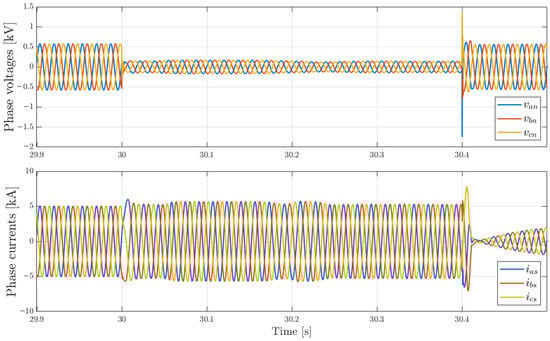
Figure 11.
Phase Voltages and Currents of the Wind Turbine during LVRT.
The upper waveform of Figure 11 shows the GSC terminal voltage responses (). After the voltage rapidly decreases, it remains in a low-voltage state for a certain period, and oscillations occur when it recovers at the release point. At this time, the grid fault-point voltage falls to about 0.1 pu, but since reactive current is prioritized at LVRT entry, the terminal voltage is maintained at about 0.3 pu. After LVRT is cleared, the current reference switches back to active current supply mode, and the active current gradually increases. Accordingly, the phase currents also show a linear increase and recover to the steady-state operating point.
4.3. Case 1: Active Power at 100% with LVRT Duration of 400 ms
Figure 12 shows the system response under varying damping coefficients, where the generator output operates at rated power (100%), an LVRT occurs at 30 s, lasts for 400 ms, and then recovers to rated power within 2 s.
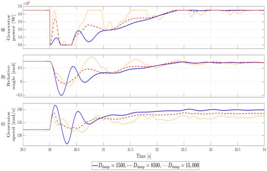
Figure 12.
Simulation results for Case 1. Active power: 100%, LVRT duration: 400 ms.
When the damping coefficient is set to 1500, significant torsional vibrations occur, with the relative angle oscillating widely in the opposite direction, showing a variation of about 1.25 rad up to the maximum torsional angle in steady state. In contrast, when the optimal value of 8500 obtained from the heatmap in Figure 8b is applied, the vibration amplitude is effectively suppressed and the excessive torsion in the opposite direction is also mitigated, resulting in a relative angle variation of about 0.814 rad with the most stable response. However, when the damping coefficient is increased to 15,000, the torsional angle in the opposite direction increases compared to that at 8500, resulting in a variation of about 0.917 rad, with a longer system settling time and more pronounced residual oscillations. The quantitative comparison of maximum torsional angles for various damping coefficients in Case 1 is summarized in Table 4, supporting the trends discussed above.
Table 4.
Quantitative Comparison of Maximum Torsional Angle Reduction under LVRT for Case 1. Active power: 100%, LVRT duration: 400 ms.
Therefore, in situations such as LVRT where torque changes abruptly and the relative angle twists significantly in the opposite direction, it can be confirmed that setting an appropriate level of damping coefficient is essential. In particular, an excessively high damping coefficient may overly constrain the system response and degrade dynamic performance; hence, a value around 8500 provides the optimal balance, achieving roughly 35% superior vibration suppression while maintaining dynamic characteristics.
4.4. Case 2: Active Power at 100% with LVRT Duration of 20 ms
Figure 13 shows the system response under varying damping coefficients, where the generator output operates at rated power (100%), an LVRT occurs at 30 s, lasts briefly for 20 ms, and then recovers to rated power within 2 s.
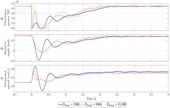
Figure 13.
Simulation results for Case 2. Active power: 100%, LVRT duration: 20 ms.
Compared with Case 1, despite the shorter LVRT duration, the maximum opposite-direction amplitude of the torsional response did not show a significant difference. When the damping coefficient was set to 1500, the maximum torsional angle in the opposite direction reached about 1.203 rad, the largest value, whereas setting it to 8500 resulted in the smallest amplitude of about 0.814 rad, confirming a stable response. On the other hand, when the damping coefficient was increased to 15,000, the variation increased to about 0.852 rad, the system stabilization time became longer, and unnecessary residual oscillations appeared. The quantitative comparison of maximum torsional angles for various damping coefficients in Case 2 is summarized in Table 5, confirming the same tendency described earlier.
Table 5.
Quantitative Comparison of Maximum Torsional Angle Reduction under LVRT for Case 2. Active power: 100%, LVRT duration: 20 ms.
In addition, because the LVRT duration is short, recovery begins before the maximum torsional angle is reached, so when the damping coefficient is 1500 or 15,000, the variation is somewhat reduced compared with Case 1. However, overall, setting it to 8500 shows about 32% better vibration suppression performance than at 1500, confirming that it is the optimal value that best satisfies the balance between vibration suppression and dynamic characteristic retention.
4.5. Case 3: Active Power at 20% with LVRT Duration of 400 ms
Figure 14 shows the system response under varying damping coefficients, where the generator output is operating at 20% of rated power, an LVRT occurs at 30 s, lasts for 400 ms, and recovers within about 2 s.
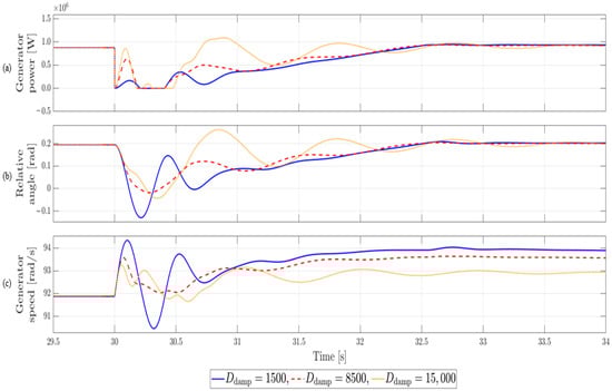
Figure 14.
Simulation results for Case 3. Active power: 20%, LVRT duration: 400 ms.
This case examines how the system responds when the effective power is low, and it can be seen that the magnitude of the shaft torsional vibration is generally reduced compared to the rated output condition. When the damping coefficient was set to 1500, the maximum torsional angle was about 0.338 rad, while at 8500 it decreased to about 0.212 rad, showing approximately 37% vibration suppression. On the other hand, when raised to 15,000, the variation increased to about 0.246 rad compared with 8500, and the system stabilization time also tended to be longer. The quantitative comparison of maximum torsional angles for various damping coefficients in Case 3 is summarized in Table 6, further supporting the previously discussed behavior.
Table 6.
Quantitative Comparison of Maximum Torsional Angle Reduction under LVRT for Case 3. Active power: 20%, LVRT duration: 400 ms.
In addition, as active power decreases, the reduction in active power due to LVRT also diminishes, and correspondingly, the peak of the damping active power and the amplitude of the relative angle both decrease. However, when the damping coefficient is set excessively high, the peak of the active power increases, and the active power that decreased at LVRT entry rises again. This can nullify the intended mitigation effect of reducing generator torque, and in wind turbines with a DC-link structure without a chopper, the incoming generator power cannot be effectively absorbed, placing a burden on the system.
Therefore, even under low output conditions, the optimal damping coefficient is still found to be around 8500, but if the objective is not strictly minimizing relative angle variation, applying a slightly lower value than 8500 may be advantageous in terms of power system stability. In other words, even under low output conditions, it is desirable to adjust the damping coefficient within a range that ensures more than 30% vibration suppression performance while avoiding unnecessary rebounds of active power.
4.6. Case 4: Active Power at 20% with LVRT Duration of 20 ms
Figure 15 shows the system response under varying damping coefficients, where the generator output is operating at 20% of rated power, an LVRT occurs at 30 s, lasts briefly for 20 ms, and recovers within about 2 s.
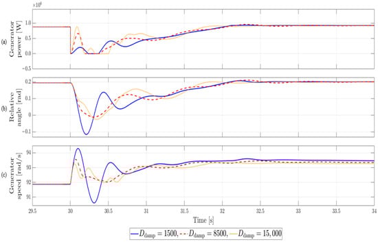
Figure 15.
Simulation results for Case 4. Active power: 20%, LVRT duration: 20 ms.
This case examines the system behavior under conditions of low active power and short LVRT duration. The overall vibration magnitude was much smaller than under rated output conditions, but the differences due to damping coefficient were still clearly observed. With the damping coefficient set to 1500, the maximum torsional angle was about 0.311 rad, while at 8500 it was reduced to about 0.207 rad, showing approximately 33% vibration suppression. On the other hand, when increased to 15,000, the maximum torsional angle was about 0.22 rad, larger than the optimal value at 8500, and the settling time also became longer. The quantitative comparison of maximum torsional angles for various damping coefficients in Case 4 is summarized in Table 7, reinforcing the overall trend described above.
Table 7.
Quantitative Comparison of Maximum Torsional Angle Reduction under LVRT for Case 4. Active power: 20%, LVRT duration: 20 ms.
In addition, as described in Case 3, the peak of the damping active power and the amplitude of the relative angle decreased proportionally to the reduction in active power caused by LVRT. However, if the damping coefficient is set excessively high, the peak active power increases, and the active power suppressed at LVRT entry can rebound. This can partially nullify the mitigation effect intended by reducing generator torque, and in DC-link structures without a chopper, the sudden incoming generator power cannot be absorbed, posing a risk to system stability.
Therefore, even when the LVRT duration is very short and recovery begins before reaching the maximum amplitude, proper selection of the damping coefficient remains important. These results show that the smallest amplitude and fastest stabilization can be achieved at around 8500, but if minimizing the relative angle is not the sole objective, slightly lower values than 8500 can also be considered. In other words, even under short LVRT conditions, applying the optimal damping coefficient is a key factor in ensuring system reliability, and at the same time, flexible adjustment of the value according to power system operating conditions is necessary.
In summary, the maximum shaft torsional angle used in this study can be interpreted as a direct indicator of the cyclic stress amplitude applied to the shaft. The 30–37% reduction in torsional angle achieved with the optimal damping coefficient (≈8500) therefore corresponds to an equivalent reduction in fatigue loading. Moreover, during LVRT events, electrical behaviors such as terminal voltage, reactive current injection, and DC-link voltage remained stable regardless of variations in , demonstrating that the proposed adaptive damping method selectively modifies the mechanical torsional response without interfering with the electrical control loops. Additionally, independent analysis performed using the NREL 5 MW reference turbine confirmed a similar optimal damping trend, supporting the general applicability of the proposed method to MW-class Type-4 wind turbines. These observations suggest that the proposed technique offers a practical tool for enhancing drivetrain mechanical reliability under LVRT conditions.
5. Conclusions
This study proposes a novel damping coefficient determination method based on the separation of steady-state and transient components to suppress shaft torsional vibrations in two-mass drivetrains under low-voltage ride-through (LVRT) conditions. Unlike conventional pole-based approaches—which define the damping coefficient solely from the poles of the transfer function and thus fail to fully reflect the influence of transmission zeros—the proposed method directly integrates the transient component of the generator speed response to calculate the maximum torsional angle. This enables quantitative control of the damping performance even under transient operating conditions. PSCAD simulations confirm that the proposed approach effectively alleviates mechanical stress during LVRT, reducing the maximum torsional angle by approximately 30–37% compared with fixed-coefficient methods.
The analysis reveals that increasing the damping coefficient enhances the damping ratio of the high-frequency torsional mode but simultaneously amplifies the residual oscillation of the low-frequency mode, leading to an optimal value (≈8500) where the modal energy of the two modes becomes balanced. This indicates that the redistribution of modal energy between the fast and slow torsional modes fundamentally governs the stability of the shaft response. The point at which this balance is achieved defines a quantitatively interpretable modal stability margin, demonstrating that the proposed selection of the optimal damping coefficient is not merely a numerical optimization result but is grounded in a theoretically sound design rationale. The adaptive algorithm was implemented as a dynamic-link library (DLL) module within PSCAD and verified for real-time execution on a DSP-based controller, demonstrating its practical applicability for integration as a drivetrain protection function within LVRT control schemes. While previous studies primarily focused on resonance suppression during steady-state operation, this work addresses transient torque fluctuations under LVRT, presenting a method that minimizes the maximum torsional angle and thus ensures system stability in both steady and transient states.
For analytical transparency, linear approximations were applied, and friction terms were neglected; however, additional damping effects due to internal friction are expected in real systems. Although the analysis employed a two-mass model, the framework can be extended to multi-mass systems to account for complex resonant behavior in large-scale turbines. In conclusion, the proposed method provides a quantitative and physically grounded design framework for controlling torsional vibrations induced by torque transients during LVRT, offering substantial contributions toward improving drivetrain reliability and the development of protective control strategies for modern wind turbines.
Author Contributions
Conceptualization, M.-J.J. and Y.-C.K.; methodology, M.-J.J. and Y.-C.K.; formal analysis, M.-J.J.; software, M.-J.J.; validation, M.-J.J. and Y.-C.K.; writing—original draft preparation, M.-J.J.; writing—review and editing, Y.-C.K. and S.-H.S.; visualization, M.-J.J.; supervision, S.-H.S.; project administration, S.-H.S. All authors have read and agreed to the published version of the manuscript.
Funding
This study was supported by the Korean Energy Technology Evaluation and Planning (KETEP) and Kwangwoon University (grant numbers 20223030020110 and 2025-0492).
Data Availability Statement
The datasets generated during and/or analyzed during the current study are available from the corresponding author upon reasonable request. The data are not publicly available due to confidentiality agreements.
Conflicts of Interest
The authors declare no conflicts of interest.
Appendix A
Factoring out the term from the denominator of the transfer function in Equation (7) and simplifying the remaining quartic yields the following expression.
Dividing both sides of the general quartic equation by yields the following form.
Defining , , , simplifies the equation to the following form.
In Equation (A3), by substituting to eliminate the term, the following equation is obtained.
Additionally, the definitions required to obtain the roots are as follows.
Accordingly, using the above procedure and definitions, the roots of the quartic equation can be expressed as follows.
The roots obtained in this way can be arranged in the form of Equation (20) as follows.
References
- Liserre, M.; Cárdenas, R.; Molinas, M.; Rodríguez, J. Overview of Multi-MW Wind Turbines and Wind Parks. IEEE Trans. Ind. Electron. 2011, 58, 1081–1095. [Google Scholar] [CrossRef]
- Blaabjerg, F.; Liserre, M.; Ma, K. Power Electronics Converters for Wind Turbine Systems. IEEE Trans. Ind. Appl. 2012, 48, 708–719. [Google Scholar] [CrossRef]
- Blaabjerg, F.; Yang, Y.; Yang, D.; Wang, X. Distributed Power-Generation Systems and Protection. Proc. IEEE 2017, 105, 1311–1331. [Google Scholar] [CrossRef]
- Jiang, Z.; Hu, W.; Dong, W.; Gao, Z.; Ren, Z. Structural Reliability Analysis of Wind Turbines: A Review. Energies 2017, 10, 2099. [Google Scholar] [CrossRef]
- Li, Y.; Zhu, C.; Chen, X.; Tan, J. Fatigue Reliability Analysis of Wind Turbine Drivetrain Considering Strength Degradation and Load Sharing Using Survival Signature and FTA. Energies 2020, 13, 2108. [Google Scholar] [CrossRef]
- Moghadam, M.; Farid, A.S.; Niemeyer, P. Failure Mode Analysis and Reliability Assessment of Wind Turbine Drivetrain Components. J. Sound Vib. 2021, 501, 116054. [Google Scholar] [CrossRef]
- National Renewable Energy Laboratory. Wind Turbine Reliability: A Database and Analysis of Wind Turbine Component Failures; NREL/TP-5000-82406; National Renewable Energy Laboratory: Golden, CO, USA, 2022. [Google Scholar]
- Hansen, A.D.; Cutululis, N.A.; Markou, H.; Sørensen, P.E.; Iov, F. Grid Fault and Design-Basis for Wind Turbines—Final Report; Risø National Laboratory for Sustainable Energy, Technical University of Denmark: Roskilde, Denmark, 2010; Risø-R-1714(EN); Available online: https://orbit.dtu.dk/en/publications/grid-fault-and-design-basis-for-wind-turbines-final-report (accessed on 2 September 2025).
- Arbeiter, M.; Hopp, M.; Huhn, M. LVRT Impact on Tower Loads, Drivetrain Torque and Rotational Speed—Measurement Results of a 2-MW Class DFIG Wind Turbine. Energies 2021, 14, 3539. [Google Scholar] [CrossRef]
- Bossanyi, E. The Design of Closed-Loop Controllers for Wind Turbines. Wind Energy 2000, 3, 149–163. [Google Scholar] [CrossRef]
- Li, Z.; Tian, S.; Zhang, Y.; Li, H.; Lu, M. Active Control of Drive Chain Torsional Vibration for DFIG-Based Wind Turbine. Energies 2019, 12, 1744. [Google Scholar] [CrossRef]
- Liu, S.; Cirstea, R.G.; Wu, H.; Bosma, T.; Wang, X. Comparative Evaluation of Converter Control Impact on Torsional Dynamics of Type-IV Grid-Forming Wind Turbines. IEEE Trans. Sustain. Energy 2024, 15, 2803–2814. [Google Scholar] [CrossRef]
- Takahashi, K.; Takahashi, R.; Tamura, J. Output Control of Three-Axis PMSG Wind Turbine Considering H∞ Observer-Based Torsional Vibration Suppression. Energies 2020, 13, 3474. [Google Scholar] [CrossRef]
- Lu, L.; Huang, J.; Wu, C. Torsional Oscillation Damping in Wind Turbines with Virtual Synchronous Machine-Based Frequency Response. Wind Energy 2022, 25, 1754–1771. [Google Scholar] [CrossRef]
- Zhang, H.; Wang, B.; Xu, C. Coordinated Model Predictive Control for Grid-Connected Wind Turbines Under Low-Voltage Ride-Through Conditions. IEEE Trans. Power Syst. 2022, 37, 5057–5068. [Google Scholar] [CrossRef]
- Boukhezzar, B.; Siguerdidjane, H. Nonlinear control of a variable-speed wind turbine using a two-mass model. IEEE Trans. Energy Convers. 2011, 26, 149–162. [Google Scholar] [CrossRef]
- Singh, M.; Muljadi, E.; Jonkman, J.; Gevorgian, V. Simulation for Wind Turbine Generators—With FAST and MATLAB-Simulink Modules. In NREL Technical Report; National Renewable Energy Laboratory: Golden, CO, USA, 2014; 137p. [Google Scholar] [CrossRef]
- Kim, Y.; Woo, B.; Song, S. Real-Time Estimation of MPPT Reference Point in Frequency Droop Controlled Wind Turbines. Trans. Korean Inst. Power Electron. 2025, 30, 148–158. [Google Scholar] [CrossRef]
- Chen, Z.; Guerrero, J.M.; Blaabjerg, F. A Review of the State of the Art of Power Electronics for Wind Turbines. IEEE Trans. Power Electron. 2009, 24, 1859–1875. [Google Scholar] [CrossRef]
- Kim, B.; Song, S. EMT Modeling and Application of Type-4 Wind Turbine Systems: Harmonic Resonance Analysis for Pre-evaluation of Grid Connection. J. Korean Wind Energy Assoc. 2025, 16, 13–27. [Google Scholar] [CrossRef]
- Yan, X.; Venkataramanan, G.; Flannery, P.S.; Wang, Y.; Dong, Q.; Zhang, B. Voltage-Sag Tolerance of DFIG Wind Turbine with a Series Grid Side Passive-Impedance Network. IEEE Trans. Energy Convers. 2010, 25, 1048–1056. [Google Scholar] [CrossRef]
- Morren, J.; de Haan, S.W.H. Ridethrough of Wind Turbines with Doubly-Fed Induction Generator During a Voltage Dip. IEEE Trans. Energy Convers. 2005, 20, 435–441. [Google Scholar] [CrossRef]
- Zhan, L.; Bollen, M.H.J. Characteristic of Voltage Dips (Sags) in Power Systems. IEEE Trans. Power Deliv. 2000, 15, 827–832. [Google Scholar] [CrossRef]
- IEEE Std 2800-2022; IEEE Standard for Interconnection and Interoperability of Inverter-Based Resources (IBRs) Interconnecting with Associated Transmission Electric Power Systems. IEEE: New York, NY, USA, 2022. [CrossRef]
- KEPCO. Renewable Energy Technical Connection Code for Transmission Level; KEPCO: Seoul, Republic of Korea, 2024; p. 8. [Google Scholar]
- Muljadi, E.; Kim, J.; Park, J.-W.; Kang, Y. Adaptive Hierarchical Voltage Control of a DFIG-Based Wind Power Plant for a Grid Fault. IEEE Trans. Smart Grid 2016, 7, 2980–2990. [Google Scholar] [CrossRef]
- Xiang, D.; Ran, L.; Tavner, P.J.; Yang, S. Control of a Doubly Fed Induction Generator in a Wind Turbine During Grid Fault Ride-Through. IEEE Trans. Energy Convers. 2006, 21, 652–662. [Google Scholar] [CrossRef]
- Lima, F.K.A.; Luna, A.; Rodriguez, P.; Watanabe, E.H.; Blaabjerg, F. Rotor Voltage Dynamics in the Doubly Fed Induction Generator During Grid Faults. IEEE Trans. Power Electron. 2010, 25, 118–130. [Google Scholar] [CrossRef]
- Chen, W.; Xu, D.; Zhu, N.; Chen, M. Control of Doubly Fed Induction Generator to Ride Through Recurring Grid Faults. IEEE Trans. Power Electron. 2015, 31, 1. [Google Scholar] [CrossRef]
- Santos-Martin, D.; Rodriguez-Amenedo, J.L.; Arnalte, S. Providing Ride-Through Capability to a Doubly Fed Induction Generator Under Unbalanced Voltage Dips. IEEE Trans. Power Electron. 2009, 24, 1747–1757. [Google Scholar] [CrossRef]
- Bossanyi, E.; Witcher, D. Controller for 5 MW Reference Turbine. In UPWIND Project Report; Document No. 11593/BR/04, Rev. A.; National Technical University of Athens/Garrad Hassan & Partners Ltd.: Bristol, UK; Athens, Greece, 2009. [Google Scholar]
- Nam, Y. Wind Turbine System Control; GSIntervision: Seoul, Republic of Korea, 2013; 550p. [Google Scholar]
- Neumark, S. Solution of Cubic and Quartic Equations; Pergamon: New York, NY, USA, 1965. [Google Scholar]
Disclaimer/Publisher’s Note: The statements, opinions and data contained in all publications are solely those of the individual author(s) and contributor(s) and not of MDPI and/or the editor(s). MDPI and/or the editor(s) disclaim responsibility for any injury to people or property resulting from any ideas, methods, instructions or products referred to in the content. |
© 2025 by the authors. Licensee MDPI, Basel, Switzerland. This article is an open access article distributed under the terms and conditions of the Creative Commons Attribution (CC BY) license (https://creativecommons.org/licenses/by/4.0/).