Abstract
This paper describes the modeling, simulation, and experimental validation of a Hybrid supercapacitor–battery Energy Storage System (HESS) for photovoltaic (PV) modules under partial shading. The system is intended to provide an uninterruptible power supply for a DC primary load. The Hybrid Power System (HPS) architecture includes a DC/DC boost converter with a Maximum Power Point Tracking (MPPT) algorithm that optimizes photovoltaic (PV) energy extraction. Furthermore, two bidirectional DC–DC converters are dedicated to the battery and supercapacitor subsystems to allow the bidirectional power flow within the HPS. The proposed HESS is evaluated through MATLAB/Simulink simulations and experimentally validated on a prototype using real-time hardware based on the dSPACE DS1104. To optimize power flow within the HPS, two energy management strategies are implemented: the Thermostat-Based Method (TBM) and the Filter-Based Method (FBM). The results indicate that the thermostat-based strategy provides better battery protection under shading conditions. Indeed, with this approach, the battery can remain in standby for 300 s under total permanent shading (100%), and for up to 30 min under dynamic partial shading, thereby reducing battery stress and extending its lifetime.
1. Introduction
In recent years, solar photovoltaic (PV) energy has become one of the fastest-growing renewable technologies worldwide [,]. As its penetration increases, the inherent variability of solar radiation on hourly, daily, and seasonal timescales presents significant challenges for balancing generation and demand. Consequently, energy storage systems are essential for stabilizing PV power generation and ensuring a reliable supply to the load [,]. In this context, Hybrid Energy Storage Systems (HESSs), combining batteries and supercapacitors, offer a promising solution to mitigate PV intermittency and load fluctuations []. These two technologies exhibit complementary characteristics: batteries provide high energy density but are limited in power output, whereas supercapacitors deliver high power despite their low energy capacity []. Integrating these technologies in a HESS improves the balance between supply and demand, enhances power quality, mitigates PV intermittency, and contributes to voltage and frequency regulation in AC microgrids [].
HESSs have been widely investigated for various applications. In grid-connected systems, they help smooth PV fluctuations, reduce grid impact, and mitigate overvoltage issues []. Supercapacitors also play a key role in reducing battery degradation, especially under rapid PV power ramps []. In off-grid or isolated systems, HESSs increase flexibility in energy flow management and support supply–demand balance under variable operating conditions [].
One of the most critical challenges in PV systems is partial shading, which reduces the effective solar irradiation on PV modules and causes significant drops in power output [,,,]. This phenomenon may result from snow, trees, buildings, or passing clouds and is particularly common in large-scale installations and building-integrated PV systems. Partial shading not only decreases energy production but also induces fast transients that are difficult to manage using conventional storage alone.
To exploit the full potential of HESSs, advanced energy management systems (EMSs) are required to coordinate power flows among PV panels, batteries, and supercapacitors. Existing EMS approaches include rule-based control, optimal control, neural networks, wavelet transforms, filtration-based methods, and fuzzy logic []. Most research to date has focused on electric or hybrid electric vehicles [,,], where EMSs are designed to enhance battery lifetime, efficiency, and dynamic performance. More recently, HESSs and EMSs have also been applied to residential and industrial PV systems, isolated microgrids, fast-charging stations, and autonomous platforms such as drones and marine vehicles [,,]. In such applications, strategies including rule-based logic, dynamic programming, and advanced control approaches such as neural networks and fuzzy logic have been investigated [,].
In previous works, most studies on HESSs have focused either on PV systems without HESS integration or on EMS performance under steady irradiance and load conditions. Accordingly, both the specific impact of supercapacitors on shading-induced transients and the effectiveness of different EMS strategies in these situations remain largely unexplored. Few studies have examined the combined impact of partial shading and EMS design in PV–HESS stability. In this context, the present work focuses on PV/Battery/Supercapacitor dynamics under partial shading, compares two complementary rule-based EMS strategies (Thermostat-Based Method (TBM) vs. Filter-Based Method (FBM)), and provides both simulation and experimental validation. It thereby offers new insights into the role of supercapacitors in mitigating shading-induced fluctuations and extending battery lifetime. The main contributions of this study are:
- 1.
- Development of a PV/Battery/Supercapacitor hybrid system able to operate under partial shading conditions while maintaining a stable output power and voltage.
- 2.
- Design and comparative evaluation of two EMS strategies (TBM and FBM) used to optimize power flow and reduce battery stress.
- 3.
- Simulation and experimental validation, confirming the effectiveness of the proposed approach under realistic shading scenarios.
Considering the novel findings discussed above, this work investigates, through simulations and experimental implementation, the role of supercapacitors in smoothing PV power fluctuations during shading events and alleviating battery stress. The obtained results show that when supercapacitors are prioritized to balance power supply and load demand under shading effects (TBM), the battery can remain on standby for up to 300 s during total permanent shading and up to 30 min under dynamic shading conditions, unlike in the other strategies where it is continuously active. This EMS strategy significantly reduces battery degradation and lowers maintenance costs.
The remainder of this paper is structured as follows. Section 2 presents the system modeling, Section 3 describes the EMS strategies, Section 4 discusses the simulation results, Section 5 reports the experimental validation, and Section 6 concludes the paper with key findings and future research directions.
2. System Description and Modeling
The integration of PV systems with HESSs enhances the efficient use of solar energy, optimizes energy management, and improves overall system stability. The most widely adopted topologies in battery–supercapacitor-based HESSs for PV applications are discussed below []:
2.1. Different Topologies of HESSs Combining Batteries and Supercapacitors
2.1.1. PV System with Passive Hybrid Battery–Supercapacitor HESS Configuration
As shown in Figure 1a, this configuration connects the photovoltaic generator to a charge controller. The passive connection of the battery and supercapacitor to the DC bus is simple and cost-effective, providing effective suppression of transient currents and stabilization of the system voltage. However, it does not fully exploit the transient capability of the supercapacitor and limits its volumetric efficiency due to the small variation in battery terminal voltage and the dependence on the respective internal resistances [].
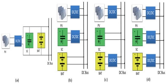
Figure 1.
(a) PV with passive battery-supercapacitor HESS; (b) PV with semi-active supercapacitor/battery HESS; (c) PV with semi-active battery–supercapacitor HESS; (d) PV with full active battery–supercapacitor HESS.
2.1.2. PV System with Semi-Active Battery–Supercapacitor Configuration
In this topology, a DC/DC converter interfaces the PV array, while a bidirectional DC/DC converter connects one Energy Storage System (ESS), enabling active control of a single storage unit. Figure 1b shows a semi-active HESS in which the supercapacitor is connected to the common DC bus through a bidirectional DC/DC converter, while the battery is directly connected to the DC bus. Conversely, in Figure 1c, the battery is interfaced via a bidirectional DC/DC converter, and the supercapacitor is directly connected to the DC bus. These configurations provide better control flexibility and improve efficiency while remaining cost-effective by reducing the number of required converters. However, this approach limits the utilization of the passive storage unit, increases management complexity, and may induce imbalances in the charge–discharge cycles [].
2.1.3. PV System with Full Active HESS
This configuration employs MPPT algorithms to optimize the PV array’s power output by continuously tracking the maximum power point. The MPPT controller adjusts the PV array’s operating point to extract maximum power under varying environmental conditions, thereby maximizing the energy extracted from the photovoltaic generator and improving the overall performance of the PV–Battery–Supercapacitor system. Both the battery and supercapacitor are actively controlled to store excess energy during periods of high solar irradiance, ensuring efficient energy use and providing backup power during low irradiance or high-demand periods, as shown in Figure 1d. Although this configuration increases system complexity and cost, it offers greater flexibility in power flow management and improves the lifetime of the storage components [].
In this study, a fully active HESS is adopted with a PV panel controlled by a PSO-based MPPT algorithm, as shown in Figure 2. The PV module is connected to the common DC bus through a non-isolated boost converter, while the battery and supercapacitor are connected via non-isolated bidirectional DC/DC converters, allowing bidirectional power flow between the DC bus and the HESS components [,].
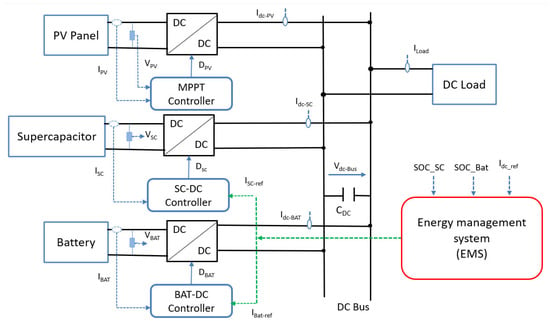
Figure 2.
Fully active HESS (battery–supercapacitors).
2.2. Modeling of the HESS
The system under study comprises PV panels, batteries, supercapacitors (SC), and multiple power converters, with detailed modeling provided for each component.
2.2.1. Modeling of PV Panels
The PV module consists of series-connected PV cells to increase the output voltage. The cells are organized into parallel subgroups, each protected by bypass diode.
The general equivalent circuit, depicted in Figure 3, includes a photocurrent source, a diode, a parallel resistor (RSH) representing leakage current, and series resistors (RS) representing internal resistance to current Flow [].
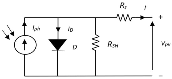
Figure 3.
Equivalent circuit of the one-diode PV cell.
The current-voltage characteristic equation of a solar cell is given by [,]:
with:
where Iph represents the photocurrent, IS the cell’s saturation dark current, q denotes the electron charge (q = 1.6 × 10⁻¹⁹ C), k is the Boltzmann constant (k = 1.3 × 10⁻²³ J/K), IRS is the cell’s short-circuit current at 25 °C and 1000 W/m2, TRef is the cell’s reference temperature, Tc is the cell’s operating temperature, A is the ideality factor, and Ir represents solar insulation.
Multiple PV modules are interconnected in series and parallel to achieve the desired voltage and current, forming a PV array. The array output current (I), with Ns series modules and Np parallel modules, is given by:
In this study, the Siemens SM55 photovoltaic (PV) module is employed (Siemens, Manchester, UK). The module consists of 36 monocrystalline PowerMax® solar cells (Powermax Renewable Energy Technology Co.,Ltd., Wuxi, China) and incorporates two bypass diodes to mitigate partial shading effects and prevent hot spots as shown in Figure 4. Table 1 summarizes the other electrical parameters of the PV module.

Figure 4.
Structure of the Siemens SM55 PV Module.

Table 1.
Parameter of the PV module (SM55).
Figure 5 illustrates the impact of partial shading on the P–V characteristics of the PV module. Under uniform irradiation of 1000 W/m2, the module exhibits a standard P–V curve with a single maximum power point (MPP). However, when a block of 9 cells is shaded at 500 W/m2, a discontinuity appears, producing a multi-peak P–V characteristic with two distinct MPPs.
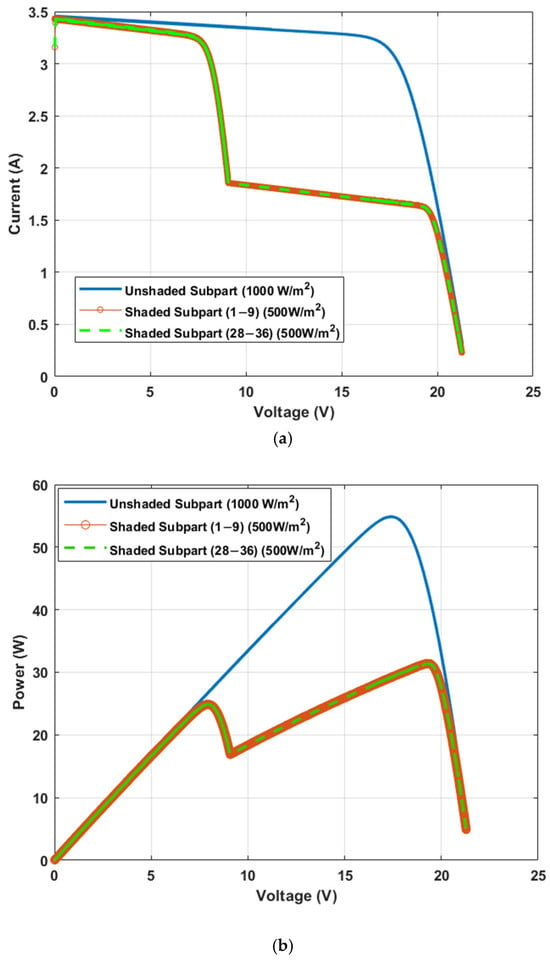
Figure 5.
Current-Voltage and Power-Voltage curves of PV module under partial shading: (a) I–V curves; (b) P–V curves.
A PSO algorithm is developed to enhance MPPT in PV systems under partial shading conditions. Unlike conventional techniques that may converge to local maxima due to the multi-peak nature of the PV power–voltage curve, the PSO approach ensures global optimization. By mimicking the collective behavior of bird flocks or fish schools, a swarm of candidate solutions explores the search space and converges toward the optimal duty cycle of the DC–DC boost converter. This allows the system to reliably extract the maximum available power, even under rapidly changing irradiance. The flowchart of the PSO- MPPT algorithm is shown in Figure 6.
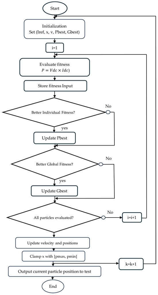
Figure 6.
Flowchart of the PSO-MPPT algorithm.
2.2.2. Modeling of the SCs
The electrical behavior of a supercapacitor is commonly represented by an equivalent circuit model comprising a capacitance in series with a resistance that characterizes the equivalent series resistance (ESR). To account for self-discharge phenomena, a leakage resistance is introduced in parallel with the capacitance, referred to as the equivalent parallel resistance (EPR), as illustrated in Figure 7 [].
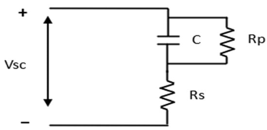
Figure 7.
Equivalent circuit model of the supercapacitor.
The sizing procedure of the supercapacitor module is determined according to the required power (P) and the duration over which the module must supply this power (t) [,]. The adopted sizing methodology, illustrated in Figure 8, involves the following steps:
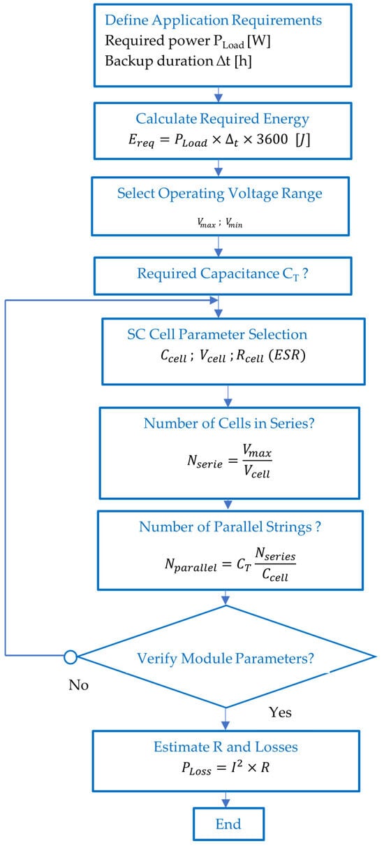
Figure 8.
Flowchart—Supercapacitor Module Sizing.
(i) Define the nominal voltage and current levels.
(ii) Compute the total capacitance required for the supercapacitor module.
(iii) Determine the number of elements to be connected in series (Nseries) and in parallel (Nparallel).
The following parameters are defined:
Vscmax: maximum voltage of the supercapacitor module
Vscmin: minimum voltage of the supercapacitor module. When the module discharges from , approximately 75% of the stored energy is delivered.
CT: total capacitance of the supercapacitor module.
R: total equivalent series resistance of the supercapacitor module.
The total capacitance (CT) and internal resistance (R) of the supercapacitor module are determined by the configuration of cells connected in series and/or parallel. These parameters are expressed as:
where
C: capacitance of a single cell; ESR: equivalent series resistance of a single cell.
Nseries: number of cells connected in series; Nparallel: number of cells connected in parallel.
The required number of series-connected cells (Nseries) is determined by dividing the target maximum module voltage (Vscmax) by the maximum allowable voltage of a single supercapacitor cell. Under specified temperature and time conditions, the temporal evolution of the module terminal voltage is governed by the following equation:
where I represent the average discharge current, defined as:
and P is the constant output power of the module.
The energy stored in the supercapacitor is determined by the classical expression for capacitive energy, given as:
The state of charge of the supercapacitor (SOCsc) is a dimensionless parameter that indicates the ratio of the energy currently stored in the supercapacitor to its maximum energy storage capacity. The SOCsc is calculated using []:
In this study, the hybrid energy storage system (HESS) is designed to supply a 40 W load without interruption for 300 s under total shading conditions. The required energy of the supercapacitor is given by:
The supercapacitor module is operated within specified voltage limits, ranging from 8 V (minimum) to 16 V (maximum). Accordingly, the required total capacitance of the supercapacitor can be calculated as follows:
The characteristics of the individual supercapacitor cell are:
The number of supercapacitor cells to be connected in series and in parallel is determined as follows:
and:
Finally, to evaluate the power losses, the average discharge current of the supercapacitors (I) and their total equivalent series resistance (R) are calculated using the following equations:
Given that the supercapacitor BMOD0058 E016 B02 (Maxwell Technologies Inc., San Diego, CA, USA) consists of six cells connected in series (Table 2), three such modules are connected in parallel to meet the required sizing.

Table 2.
Parameter of the Supercapacitor BMOD0058 E016 B02.
2.2.3. Modeling of the Buck-Boost Converter Associated with SCs
To ensure efficient energy exchange between the DC bus and the storage elements (battery or supercapacitors), a bidirectional converter is employed to enable bidirectional power flow according to the operating mode (buck or boost) dictated by the Energy Management System (EMS) []. As shown in Figure 9, the converter consists of two switches (T1_SC and T2_SC), an output smoothing capacitor CDC, a smoothing inductor LSC, and the load RLoad []. The converter is designed to operate in continuous conduction mode.
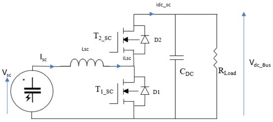
Figure 9.
Circuit configuration of the bidirectional DC–DC converter.
Since both converters are identical, the analysis focuses on the supercapacitor side, where two distinct operating phases can be identified based on the switch states [,,].
- Active phase: When the switch T1_sc is closed and the diode D2 is reverse biased, the system is defined by the following equations:
- Freewheeling phase: When the switch T1_sc is open and the diode D2 is conducting, the system equations can be expressed as follows:
The boost converter can then be represented using its average model as follows:
where represents the duty cycle of T1_sc.
Design of the Power-Stage Components in the Boost Mode
Using the equations given by [], when the bidirectional converter works in the boost mode, the power-stage components can be designed as follows:
- Maximum Duty cycle
VIN(min) = Minimum input voltage.
Vout: Desired output voltage.
η = efficiency of the boost converter (estimated at 85%).
- Inductor Ripple Current
fs: minimum switching frequency of the converter.
L: selected inductor value
D: Duty cycle calculated in equation
The inductor ripple can be written as:
where Iout(max) represents the maximum load current.
- Inductor Selection
The inductor sizing is conducted as follows:
where
: Typical input voltage.
: Desired output voltage.
: Switching frequency of the converter.
- Minimum output capacitance
The output capacitance is calculated according to the following equation:
where represents the ripple of the output voltage.
- Minimum Input capacitance
The minimum value of the input capacitance is calculated using this equation:
where represents the ripple of the input voltage.
Design of the Power-Stage Components in the Buck Mode
When the converter works in the Buck mode, the components can be designed as follows []:
- Maximum Duty cycle
- Inductor Ripple Current
- Inductor Selection
The inductor is calculated using this formula:
- Output Capacitor Selection
The output capacitor is designed using the following equations:
- Minimum Input Capacitance
The minimum input capacitance can be calculated using this formula:
Following the procedure outlined above, the power-stage components of the two bidirectional converters for the supercapacitors and the battery, as illustrated in Figure 10, are sized as summarized in Table 3 and Table 4, respectively.

Figure 10.
Power-stage components of the bidirectional converter.

Table 3.
Power stage components of the Buck-Boost Converter (SCs side).

Table 4.
Power stage components of the Buck-Boost Converter (Battery side).
The selected power-stage components correspond to the maximum values required between the boost and buck operating modes.
C1 = max (C1Buck-min, C1Boost-min)
C2 = max (C2Buck-min, C2Boost-min)
L = max (LBuck-min, LBoost-min)
The electrical parameters of the overall system are summarized in Table 5.

Table 5.
Parameters of the system.
3. Control Strategy and Energy Management System
The DC bus voltage control strategy is shown in Figure 11. A Proportional Integral (PI) controller calculates the DC bus reference current (Idc_ref) to keep the DC bus voltage at its reference value (Vdc_ref = 24 V). The energy management system (EMS) provides the battery and supercapacitor reference currents (IBat_ref and Isc_ref) and sends them to the control loop of the buck-boost converters which connect the batteries and supercapacitors to the DC bus. These currents are responsible for stabilizing the DC bus voltage regardless of the imbalance between the generated PV power and the load, as illustrated by Equations (30) and (31) [,]:
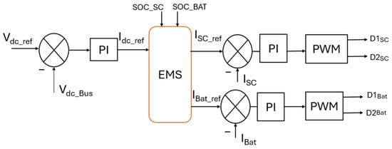
Figure 11.
Control and management of the HPS.
The load current (ILoad) is determined using the power balance on the DC side:
, and represent the DC current of supercapacitors, batteries, PV module, and dc bus, respectively.
3.1. Controller Design for the HESS
The bidirectional converter exhibits similar dynamic behavior during discharging (boost mode) and charging (buck mode), as indicated in [], resulting an identical transfer function. This characteristic enables the implementation of a unified control strategy, in which both power switches operate in a complementary manner under a common control law, as also emphasized in [,]. In this study, the boost mode is selected as the reference operating condition for controller design.
Due to the inherently faster dynamic response of the supercapacitor (SC) compared to the battery, the PI controller parameters are derived based on the SC-side power stage. To ensure system stability and suppress oscillatory behavior, the bandwidth of the SC’s inner current control loop is limited to one-sixth of the switching frequency (fsw/6), as recommended in []. To ensure that rapid transient currents are primarily handled by the SC, the battery current loop bandwidth is intentionally set lower, specifically to fsw/10. This prioritization ensures that the SC is responsible for fast energy fluctuations, while the battery contributes to slower and more sustained power demands.
To ensure stable operation, the converter bandwidth is kept significantly lower than the right-half-plane (RHP) zero frequency associated with the supercapacitor [,,]. The RHP zero frequency can be determined using the following expression:
3.1.1. Current Control Loop Design for the Supercapacitor Converter
The block diagram of the supercapacitor (SC) controller is structured with two nested loops as shown in Figure 12. An outer voltage control loop that generates the reference current of the supercapacitor (Isc_ref) and an inner current control that regulates the inductor current accordingly. The transfer function of the duty cycle to inductor current is given as follows [,].
where and are small perturbations in SC current and duty ratio of the supercapacitor converter, respectively.
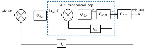
Figure 12.
Block diagram of the supercapacitor current controller and dc_Bus voltage controller.
The transfer function of the current loop compensator is given by
The open-loop transfer function of the current control loop is given by:
where denotes the transfer gain of the supercapacitor current sensor.
Figure 13 presents the Bode plot of the open-loop transfer function based on the nominal values listed in Table 5. The PI controller is designed to achieve a phase margin of 60° at a crossover frequency of 18.8 krad/s. The controller parameters are determined and fine-tuned using MATLAB’s PID Tuner, as described in [,]. The tuning procedure yields the following compensator gains: Kp_sc = 0.31 and Ki_sc = 3460.
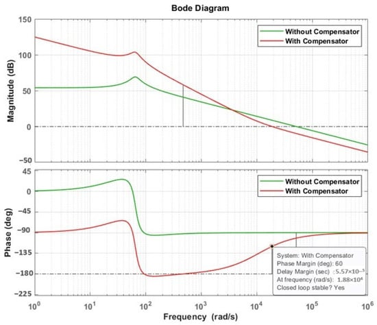
Figure 13.
Bode plot of current control loop of Supercapacitors.
3.1.2. Control Loop Design for DC Bus Voltage
The transfer function of inductor current to output voltage is given as follows [,]
where and are small perturbations in input current and output voltage of supercapacitors converter.
The transfer function of the current control loop compensator is defined as:
Accordingly, the open-loop transfer function of the current control loop is expressed as:
where the closed-loop transfer function of the supercapacitor current control loop is given by:
The bloc diagram of the dc_Bus controller is given in Figure 12.
Figure 14 presents the Bode plots of the open-loop voltage control loop with and without compensation. The PI controller is designed to provide a phase margin of 60° at a crossover frequency of 1.56 krad/s. The controller gains obtained through the design process are: Kp_v = 0.34 and Ki_v = 297.5.
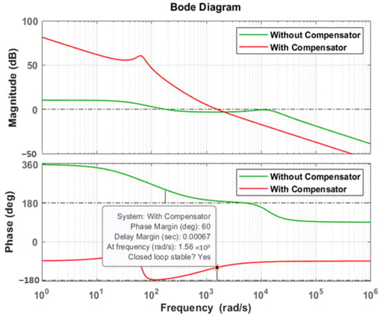
Figure 14.
Bode plot of voltage control loop.
3.1.3. Design of the Current Control Loop of the Battery
The bloc diagram of the current controller is given in Figure 15. The transfer function of the duty cycle to inductor current is given as follows [,]:
where and are small perturbations in the current and duty ratio of battery converter, respectively.

Figure 15.
Block Diagram of the Battery Current Controller.
The transfer function of the current control loop compensator is given by
The open-loop transfer function of the current control loop is given by:
where denotes the transfer gain of the battery current sensor.
Figure 16 presents the Bode plot of the open-loop transfer function based on nominal values presented in Table 5. The PI controller is designed to achieve a phase margin of 60° at a crossover frequency of 12.566 krad/s. The controller parameters are: Kp_Bat = 0.2134 and Ki_Bat = 1542.
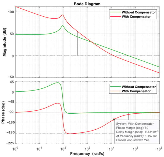
Figure 16.
Bode plot of current control loop of the battery.
3.2. Energy Management Strategy: Thermostat-Based and Filter-Based Methods
In this work, two rule-based energy management strategies are developed to coordinate power distribution among the PV array, battery, supercapacitor, and load. The proposed approaches—thermostat-based control and the Filter-Based Method (FBM)—are designed to ensure reliable and efficient energy flow under dynamic conditions such as partial shading.
The thermostat-based strategy (TBS) relies on state-of-charge (SOC) thresholds of the storage devices. The supercapacitor, owing to its high-power density and fast response, is prioritized to handle rapid power fluctuations. When its SOC falls below 50%, the battery is engaged to compensate the power deficit, thereby ensuring continuous power delivery while limiting stress on both storage units []. This hierarchical control guarantees uninterrupted power supply and prevents excessive cycling or deep discharge of the battery. To evaluate its performance, two operating scenarios are considered:
Case 1—Power deficit mode (PPV < PLoad): In this situation, the PV array is unable to meet the load demand. The supercapacitor discharges first until its SOC reaches the minimum threshold of 50%, after which the battery supplies the remaining power deficit until its SOC decreases to the lower limit of 30%. These thresholds are imposed to preserve system stability and to prolong the lifetime of the storage devices.
Case 2—Power surplus mode (PPV > PLoad): In this operating condition, the PV array generates more power than the load demand. The supercapacitor is charged first until it reaches its maximum state of charge (SOC_SC,max = 95%), after which the surplus power is allocated to the battery until its state of charge reaches SOC_Bat,max = 95%. This sequential charging strategy enhances the utilization of excess energy while ensuring system readiness for future demand or reduced solar availability.
The second strategy is the FBM, which allocates power dynamically according to the frequency content of the power flow [,,]. The FBM separates the power demand into low- and high-frequency components using a filtering process. The battery supplies the low-frequency component, corresponding to the average load demand, while the supercapacitor covers the high-frequency component associated with rapid power fluctuations. This strategy minimizes the battery’s exposure to rapid transients while exploiting the high-power handling capability of the supercapacitor. Two operating scenarios are also considered for FBM:
Case 1—Power deficit mode (PPV < PLoad): The low-frequency portion of the demand is supplied by the battery, while the high-frequency fluctuations are managed by the supercapacitor.
Case 2—Power surplus mode (PPV > PLoad): The surplus is absorbed simultaneously by the battery and the supercapacitor. The battery absorbs the low frequency components of the power where supercapacitor store high-frequency peaks until they reach their upper limits SOC = 95%.
Both strategies are implemented to evaluate their effectiveness in managing HESSs and ensuring optimal performance under partial shading conditions. The flowcharts of the respective energy management systems are presented in Figure 17.
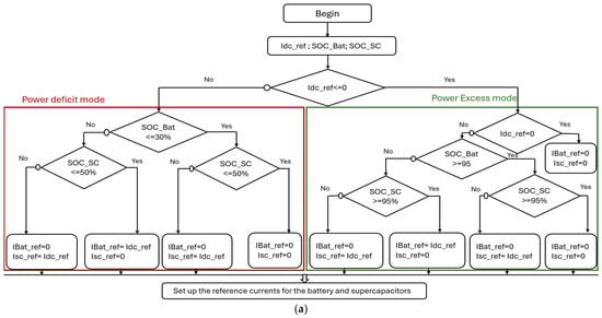
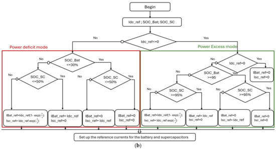
Figure 17.
Flowchart of the rule-based energy management system; (a) with TBM (b) with FBM.
4. Simulation Results and Analysis
The proposed system and its control strategy have been simulated using MATLAB/Simulink software (version R2024a). The simulation parameters are shown in Table 5 and Table 6. To verify the proposed strategy, it is assumed that the state of charge boundaries is [SOCmin = 30%, SOCmax = 95%] for the battery and [SOCmin = 50%, SOCmax = 95%] for the supercapacitors.

Table 6.
HESS parameters.
To verify the performance of the EMS strategies, the closed-loop simulation of the proposed system is performed for different cases:
4.1. Case 1: The Supercapacitor and the Battery Are Initially Charged Under Nominal Load
A dynamic shading pattern is sequentially applied to four groups of nine cells (1–9, 10–18, 19–27, and 28–36). Each shading interval of 20 s at 500 W/m2 is followed by a 10 s period at full irradiance (1000 W/m2), resulting in a total shading duration of 130 s. The irradiance profile for each sub-group is depicted in Figure 18a.
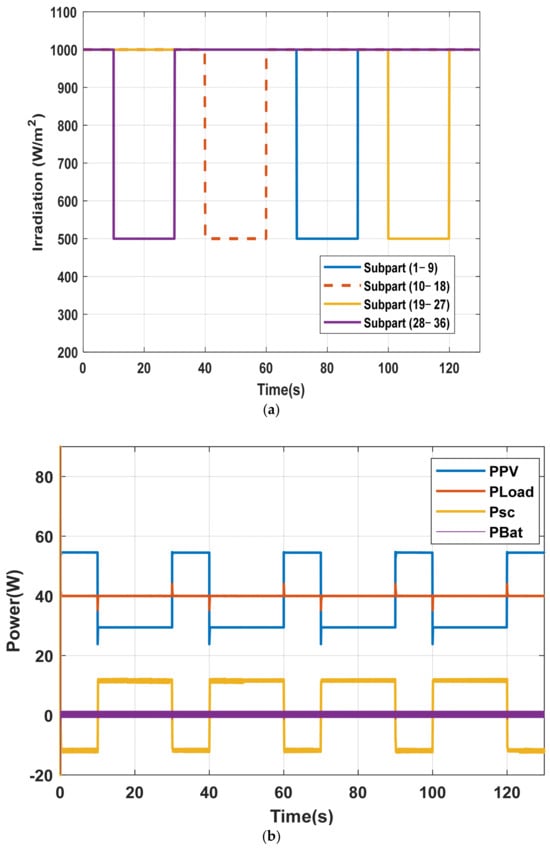
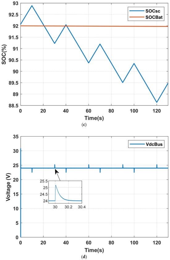
Figure 18.
System response under dynamic sequential shading scenario with TBM: (a) Applied irradiance on PV sub-groups; (b) Power profiles of PV, load, battery, and supercapacitor; (c) SOC dynamics of storage devices; (d) DC bus voltage regulation.
Under the TBM strategy, the PV power (Ppv) exhibits successive variations, while the load demand (PLoad) remains constant, as shown in Figure 18b. In this case, the supercapacitor (Psc) is activated only to mitigate fast power fluctuations, whereas the battery remains in standby throughout the entire 130 s shading period, thereby preserving its lifetime, as illustrated in Figure 18b,c. The DC bus voltage (VdcBus) is successfully regulated at 24 V, as illustrated in Figure 18d, which confirms the effectiveness of the proposed nested-loop control strategy of Figure 12.
These results highlight the role of the supercapacitor in maintaining power balance and voltage stability under dynamic shading conditions, while the battery is preserved for long-term energy support.
The same dynamic shading sequence was then simulated using the FBM strategy. In this case, both storage elements are actively engaged to mitigate the shading effect as shown in Figure 19: the supercapacitor handles high-frequency variations while the battery manages slower fluctuations of the Idc_ref current. The DC bus voltage remains consistently regulated at its reference value (24 V) throughout the entire period of the dynamic shading.
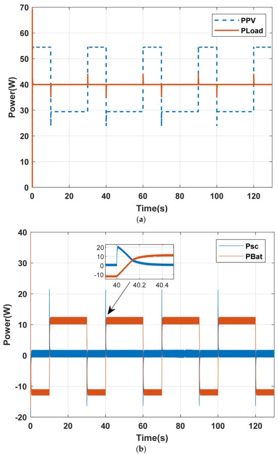
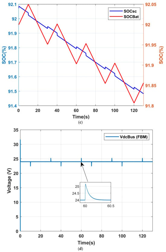
Figure 19.
System response under dynamic sequential shading scenario with FBM; (a) Power profiles of PV and load; (b) Power profiles of battery and supercapacitor; (c) SOC dynamics of storage devices; (d) DC bus voltage regulation.
4.2. Case 2: The Battery and the Supercapacitor Are Under Nominal Load, but Only the Supercapacitor Is About to Reach Its Half-Charge State
This scenario corresponds to a static partial shading condition, in which different PV submodules are subjected to unequal irradiance levels over an extended interval, as depicted in Figure 20a. Under these conditions, the PV array output is insufficient to meet the load demand throughout the shading period (130 s), as shown in Figure 20b. By applying the TBM strategy, the supercapacitor initially supports the PV module in supplying power to the load. However, after 94 s, the supercapacitor state of charge reaches its lower limit (50%). At this time the battery is activated to ensure continuous and stable load supply, as illustrated in Figure 20c,d. Meanwhile, the output voltage remains regulated during the entire shading interval, as presented in Figure 20e. These results highlight the limitation of relying solely on the supercapacitor for long-duration shading events and confirming the essential role of coordinated battery support.
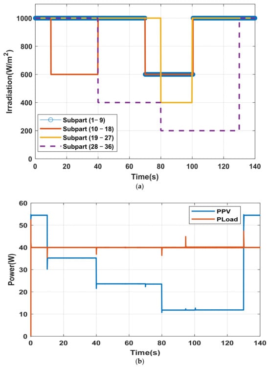
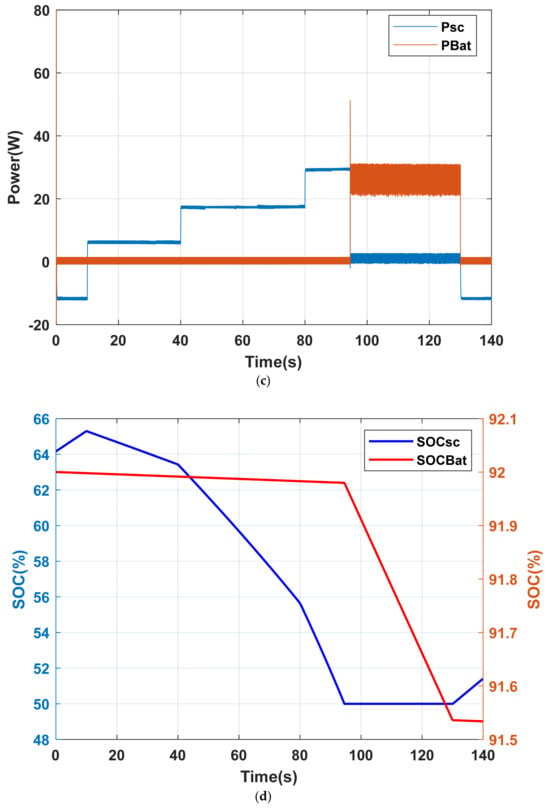
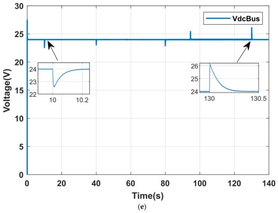
Figure 20.
System response under static partial shading scenario with TBS; (a) Applied irradiance on PV sub-groups; (b) Power profiles of PV and load; (c) Power profiles of battery, and supercapacitor; (d) SOC dynamics of storage devices; (e) DC bus voltage regulation.
The same static shading scenario was then simulated using the FBM strategy. Figure 21a presents the power profiles of the PV array and the load demand. In this case, both storage devices remain active throughout the entire shading period (130 s). The battery supplies the low-frequency component of the DC reference current, while the supercapacitor supplies the high-frequency component, as depicted in Figure 21b,c. Meanwhile, the battery operates continuously either in power deficit or surplus modes. The DC bus voltage is maintained at its reference value of 24 V, as shown in Figure 21d.
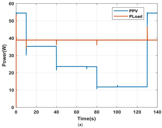
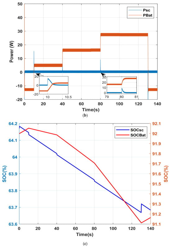
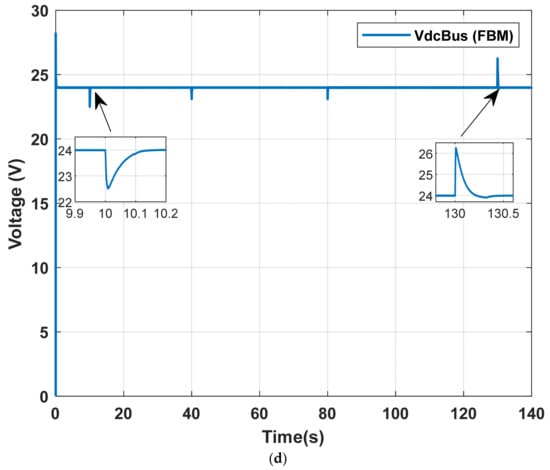
Figure 21.
System response under static partial shading scenario with FBM; (a) Power profiles of PV and load; (b) Power profiles of battery, and supercapacitor; (c) SOC dynamics of storage devices; (d) DC bus voltage regulation.
In the next section, the two energy management strategies, TBM and FBM, are comparatively analyzed to determine the optimal approach for maximizing power sharing and improving the overall reliability of the hybrid energy storage system (HSS).
4.3. Comparison of TBM and FBM Under Dynamic and Static Shading Conditions
The comparative analysis of the TBM and Filter-Based (FBM) strategies under both dynamic and static shading conditions highlights distinct operational behaviors of the hybrid battery–supercapacitor system. Under dynamic shading, TBM fully preserves the battery by relying exclusively on the supercapacitor (0 s, 0%), whereas FBM engages the battery continuously (130 s, 100%). In static shading, TBM reduces battery involvement to 25.4% of the shading period, while FBM operates the battery throughout the entire interval.
The main advantage of the TBM strategy lies in its ability to delay battery intervention, thereby protecting the battery from rapid shading-induced fluctuations and contributing to the preservation of its operational lifetime. This finding can be further confirmed by analyzing the state-of-charge indicators of the batteries and supercapacitors, as presented in Table 7. Consequently, the state-of-charge (SOC) variations confirm that TBM favors battery preservation (∆SOCBat ≤ 0.5%) but induces higher stress on the supercapacitor (∆SOCsc up to 14%), whereas FBM distributes the load between both devices, resulting in larger battery SOC variations (up to 1%) but minimal supercapacitor fluctuations (0.5%).

Table 7.
Performance indicators of TBM and FBM under shading.
Regarding voltage regulation, both strategies exhibit similar voltage deviations (10.57%), indicating comparable stability, whereas under static shading, TBM achieves slightly lower deviation (13.56% vs. 14.16%), with FBM trading a minor increase in voltage fluctuation for more balanced load sharing between the storage units.
Overall, the TBM control strategy favors supercapacitors (SCs) for handling rapid power fluctuations, reserving battery use for last-resort operation. This selective involvement significantly reduces the battery’s energy throughput, mitigates electrochemical degradation, and extends battery lifespan. In contrast, FBM involves the battery continuously—during both transient and steady-state conditions—resulting in increased energy cycling, thermal stress, and accelerated aging. As a result, TBM not only improves short-term dynamic performance, but also ensures long-term sustainability and reliability of the hybrid energy storage system.
5. Experimental Results
As illustrated in Figure 22, a practical DC-coupled PV/Battery/Supercapacitor (PVBSC) prototype was developed to validate the hybrid energy storage system (HESS) and its energy management strategy (EMS). The system is controlled using a dSPACE DS1104 platform. A non-isolated boost converter, operating at 10 kHz, regulates the power extracted from the PV source (SM55 module) using a PSO-based MPPT algorithm. This algorithm continuously requires the PV current and voltage, which are measured using LEM HY 5A and LV25-P sensors, respectively. The hybrid storage system includes 12 V–5 Ah lithium-ion battery and 16 V–58 F Maxwell BMOD0058 E016 B02 supercapacitor. Energy exchange between the HESS and the common 24 V DC bus is achieved by two bidirectional buck–boost converters, each employing two IRFP460 MOSFETs and operated at a switching frequency of 10 kHz. Because the complementary control of the bidirectional converters’ switches, an IR2110 IC is used to drive upper and lower Mosfets. A dead time of 2 µs is ensured to prevent the short circuit of the DC Bus. The load is emulated by a variable resistor.
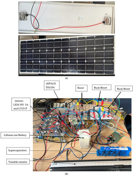
Figure 22.
DC-coupled PV/Battery/Supercapacitor (PVBSC) prototype; (a) PV module; (b) hardware developed.
Before loading the entire control system, voltage and current parameters are calibrated using the control desk interface. The calibration procedure involves applying known reference signals to the ADC channels of the DS1104 and adjusting the corresponding gain and offset parameters. This process compensates for any sensor or signal conditioning inaccuracies, ensuring that the digitized signals accurately reflect the real electrical quantities.
The performance of the prototype is assessed under two operating conditions detailed in Section 4: (1) HESS response to dynamic shading, and (2) HESS response to static partial shading.
5.1. HESS Response to Dynamic Shading
In the experimental setup, the shading phenomenon was emulated by introducing a step increase in the load demand. This approach effectively replicates the power deficit typically caused by partial or dynamic shading in real photovoltaic (PV) systems. Figure 23 illustrates the corresponding power profiles, highlighting two distinct operating modes of the proposed energy management system (EMS). In the first mode, during periods of excess PV generation, the supercapacitor absorbs and stores the surplus energy. In the second mode, which is triggered by a sudden increase in load (representing a shading-induced power shortfall), the supercapacitor discharges to supply the necessary energy.
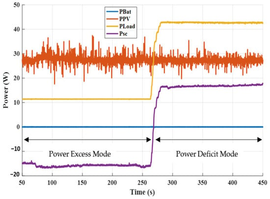
Figure 23.
Power Profiles of PV, Battery, Supercapacitor, and Load.
As shown in Figure 23 and Figure 24, the supercapacitor alone feed the additional load for approximately 175 s. During this period, the battery remained in standby mode, neither charging nor discharging. This behavior clearly demonstrates the EMS’s ability to prioritize supercapacitor usage for rapid power support while preserving the battery for long-term energy balancing. Such a strategy not only minimizes battery cycling but also contributes to extending battery lifespan.
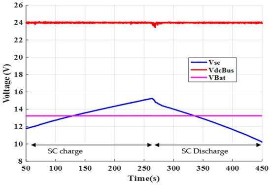
Figure 24.
DC Bus, Supercapacitor, and Battery Voltages.
Furthermore, Figure 24 confirms the effectiveness of DC bus voltage regulation under dynamic shading conditions. The DC bus voltage VdcBus was maintained within the permissible operating range throughout the entire event, without significant deviations or oscillations. This indicates that the EMS successfully coordinated the energy flow between sources and storage units to stabilize the system voltage, ensuring consistent and reliable power delivery to the load.
5.2. HESS Response to Static Partial Shading
Figure 25, Figure 26 and Figure 27 illustrate the dynamic response of the hybrid energy storage system (HESS) under static partial shading conditions. These figures present the evolution of power flows—including photovoltaic power PPV, load demand PLoad, supercapacitor power Psc, and battery power PBat—as well as the voltage profiles of the supercapacitor Vsc and the battery VBat. Based on these results, five distinct operating phases can be identified:
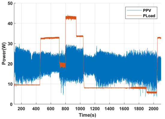
Figure 25.
Evolution of PV and load power (PPV and PLoad) under static shading.
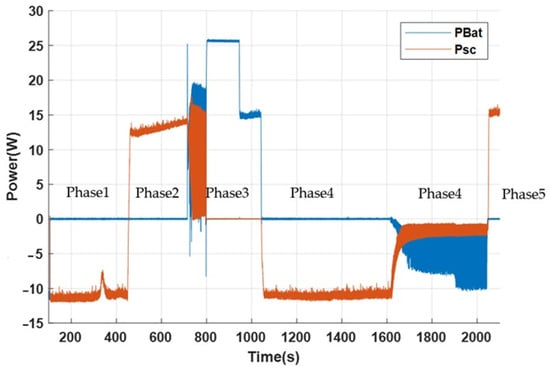
Figure 26.
Evolution of supercapacitor and battery power (Psc and PBat) under static shading.
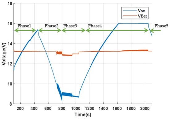
Figure 27.
Evolution of supercapacitor and battery voltages (Vsc and Vbat) under static shading.
Phase 1—Power Surplus: When PV generation exceeds the load demand, the supercapacitor is prioritized to store the excess power. This enables it to absorb fast surplus energy and prevents battery charging.
Phase 2—Power Deficit: When load increases, causing an energy shortfall, the supercapacitor discharges to balance the mismatch and continues supplying the load until its voltage reaches the predefined lower limit.
Phase 3—Battery Support: Once the supercapacitor is fully discharged, the battery is activated to provide energy support. It supplies the load for approximately 200 s, ensuring continuity of power delivery during prolonged shading.
Phase 4—Power Surplus: As the load power decreases, the supercapacitor is recharged up to its maximum limit. Any remaining surplus energy is then used to recharge the battery.
Phase 5—Power Deficit: When the load increases, the supercapacitor responds first, discharging rapidly to meet the sudden demand and ensuring stable system operation without relying on the battery.
This sequence of operations demonstrates the effectiveness of the hierarchical control strategy implemented in the EMS. The supercapacitor handles short-term power fluctuations and rapid transients, while the battery is engaged only during sustained deficits. This approach enhances overall system responsiveness and reduces battery stress, thereby extending its lifetime and improving system reliability.
6. Conclusions
This study proves the effectiveness of a hybrid battery–supercapacitor energy storage system (HESS) for PV applications under partial and dynamic shading. The proposed architecture is simulated via MATLAB/Simulink and then validated using real-time dSPACE DS1104 to ensure a reliable power supply for DC loads. The system integrates a boost converter with a maximum power point tracking (MPPT) algorithm and dual bidirectional DC–DC converters to facilitate bidirectional power flow.
Among the two implemented energy management strategies, the Thermostat-Based Method (TBM) offers better battery protection and voltage stability. Under TBM, the battery can remain in standby for up to 300 s under full shading and over 30 min during dynamic shading, thereby minimizing stress and prolonging its lifespan. Conversely, the Filter-Based Method (FBM) causes continuous battery cycling, increasing the risk of accelerated degradation.
Through this study, hybrid battery–supercapacitor energy storage systems have been shown to effectively mitigate power fluctuations, enhancing system stability and energy quality while extending battery lifespan. Future work will focus on the development of intelligent control strategies and real-time diagnostic methods to ensure reliable operation in smart grid and autonomous system applications.
Author Contributions
Conceptualization: I.C., L.K., F.G. and A.R.; Methodology: I.C. and A.R.; Original Draft Preparation: I.C., L.K. and F.G.; Review and Editing of the Final Version: I.C., L.K., F.G. and A.R.; Supervision: F.B.H., A.S. and M.B.; Funding Acquisition: A.S. and M.B. All authors have read and agreed to the published version of the manuscript.
Funding
This research was funded by the European Union under the LEAP-RE program, Grant Agreement No. 963530, as part of the SIREVIVAL project. The APC was funded by the same program.
Data Availability Statement
The data that support the findings of this study are available from the corresponding author upon reasonable request.
Acknowledgments
Authors would like to acknowledge the Ministry of Higher Education and Scientific Research of Tunisia for its support.
Conflicts of Interest
The authors declare no conflicts of interest.
Abbreviations
The following abbreviations are used in this manuscript:
| HESS | Hybrid energy storage System |
| HPS | Hybrid Power System |
| PV | Photovoltaic |
| SC | Supercapacitors |
| Bat | Battery |
| TBM | Thermostat-Based Method |
| FBM | Filter-Based Method |
| PSO | Particle Swarm Optimization |
| MPPT | Maximum Power Point Tracking |
| EMS | Energy Management System |
| LPF | Low Pass Filter |
| SOC | State of Charge |
| P | Power |
| DC | Direct Current |
| ref | reference |
References
- Argyrou, M.C.; Marouchos, C.C.; Kalogirou, S.A.; Christodoulides, P. A novel management algorithm for a residential grid-connected PV system with battery-supercapacitor storage for increased self-consumption and self-efficiency. Energy Convers. Manag. 2021, 246, 114671. [Google Scholar] [CrossRef]
- Díaz-González, F.; Chillón-Antón, C.; Llonch-Masachs, M.; Galceran-Arellano, S.; Rull-Duran, J.; Bergas-Jané, J.; Bullich-Massagué, E. A hybrid energy storage solution based on supercapacitors and batteries for the grid integration of utility-scale photovoltaic plants. J. Energy Storage 2022, 51, 104446. [Google Scholar]
- Tiwari, P.; Kafle, A.; Bijukchhe, P.; Bhattarai, A. A review on energy storage systems. J. Phys. Conf. Ser. 2021, 2629, 012024. [Google Scholar]
- Guentari, H.; Allaoui, T.; Mekki, M.; Denai, M. Power management and control of photovoltaic system with hybrid battery-supercapacitor energy storage based on heuristics methods. J. Energy Storage 2021, 39, 102578. [Google Scholar] [CrossRef]
- Sutikno, T.; Arsadiano, W.; Wangsupphaphol, W.; Yudhana, A.; Facta, M. A review of recent advances on hybrid energy storage system for solar photovoltaic power generation. IEEE Access 2022, 10, 42346–42364. [Google Scholar] [CrossRef]
- Hu, W.; Shang, Q.; Bian, X.; Zhu, R. Energy management strategy of hybrid energy storage system based on fuzzy control for ships. Int. J. Low-Carbon Technol. 2022, 17, 169–175. [Google Scholar] [CrossRef]
- Weng, L.-G.; Feng, X.-L.; Jin, D.-J.; Ying, H.-H.; Yue, S.-H. A hybrid energy storage system based on wavelet packet decomposition technology for photovoltaic power smoothing. In Proceedings of the 2023 International Conference on Power Energy Systems and Applications (ICoPESA), Nanjing, China, 24–26 February 2023; pp. 369–375. [Google Scholar]
- Atawi, I.E.; Al-Shetwi, A.Q.; Magableh, A.M.; Albalawi, O.H. Recent advances in hybrid energy storage system integrated renewable power generation: Configuration, control, applications, and future directions. Batteries 2023, 9, 29. [Google Scholar]
- Mamun, M.A.A.; Hasanuzzaman, M.; Selvaraj, J. Experimental investigation of the effect of partial shading on photovoltaic performance. IET Renew. Power Gener. 2017, 11, 912–921. [Google Scholar] [CrossRef]
- Oufettoul, H.; Lamdihine, N.; Motahhir, S.; Lamrini, N.; Abdelmoula, I.A.; Aniba, G. Comparative performance analysis of PV module positions in a solar PV array under partial shading conditions. IEEE Access 2023, 11, 12176–12194. [Google Scholar] [CrossRef]
- Wang, Y.-J.; Hsu, P.-C. An investigation on partial shading of PV modules with different connection configurations of PV cells. Energy 2011, 36, 3069–3078. [Google Scholar] [CrossRef]
- Ramezani, F.; Mirhosseini, M. Shading impact modeling on photovoltaic panel performance. Renew. Sustain. Energy Rev. 2025, 212, 115432. [Google Scholar] [CrossRef]
- Babu, T.S.; Vasudevan, K.R.; Ramachandaramurthy, V.K.; Sani, S.B.; Chemud, S.; Lajim, R.M. A comprehensive review of hybrid energy storage systems: Converter topologies, control strategies and future prospects. IEEE Access 2020, 8, 148702–148721. [Google Scholar] [CrossRef]
- Yi, F.; Lu, D.; Wang, X.; Pan, C.; Tao, Y.; Zhou, J.; Zhao, C. Energy management strategy for hybrid energy storage electric vehicles based on Pontryagin’s minimum principle considering battery degradation. Sustainability 2022, 14, 1214. [Google Scholar] [CrossRef]
- Zhang, Q.; Zhang, S.; Wu, J. A rule-based energy management system of experimental battery/supercapacitor hybrid energy storage system for electric vehicles. J. Control Sci. Eng. 2016, 2016, 6828269. [Google Scholar]
- Khalid, M. A review on the selected applications of battery-supercapacitor hybrid energy storage systems for microgrids. Energies 2019, 12, 4559. [Google Scholar] [CrossRef]
- Ali, S.; Zheng, Z.; Aillerie, M.; Sawicki, J.-P.; Péra, M.-C.; Hissel, D. A Review of DC Microgrid Energy Management Systems Dedicated to Residential Applications. Energies 2021, 14, 4308. [Google Scholar] [CrossRef]
- Liu, J.; Dong, H.; Jin, T.; Liu, L.; Manouchehrinia, B.; Dong, Z. Optimization of Hybrid Energy Storage Systems for Vehicles with Dynamic On-Off Power Loads Using a Nested Formulation. Energies 2018, 11, 2699. [Google Scholar] [CrossRef]
- Sankarkumar, R.S.; Natarajan, R. Energy management techniques and topologies suitable for hybrid energy storage system powered electric vehicles: An overview. Int. Trans. Electr. Energy Syst. 2021, 31, e12819. [Google Scholar] [CrossRef]
- Michailidis, P.; Michailidis, I.; Gkelios, S.; Kosmatopoulos, E. Artificial Neural Network Applications for Energy Management in Buildings: Current Trends and Future Directions. Energies 2024, 17, 570. [Google Scholar] [CrossRef]
- El Zerk, A.; Ouassaid, M. Real-Time Fuzzy Logic Based Energy Management System for Microgrid Using Hardware in the Loop. Energies 2023, 16, 2244. [Google Scholar] [CrossRef]
- Zimmermann, T.; Keil, P.; Hofmann, M.; Horsche, M.F.; Pichlmaier, S.; Jossen, A. Review of system topologies for hybrid electrical energy storage systems. J. Energy Storage 2016, 8, 78–90. [Google Scholar] [CrossRef]
- Jing, W.; Lai, C.H.; Wong, S.H.W.; Won, M.L.D. Battery-supercapacitor hybrid energy storage system in standalone DC microgrids: A review. IET Renew. Power Gener. 2017, 11, 461–469. [Google Scholar]
- Cabrane, Z.; Ouassaid, M.; Maaroufi, M. Analysis and evaluation of battery-supercapacitors hybrid energy storage system for photovoltaic installation. Int. J. Hydrog. Energy 2016, 41, 20897–20907. [Google Scholar] [CrossRef]
- Cabrane, Z.; Lee, S.H. Electrical and mathematical modeling of supercapacitors: Comparison. Energies 2022, 15, 693. [Google Scholar] [CrossRef]
- Hussain, S.; Ali, M.U.; Park, G.S.; Nengroo, S.H.; Khan, M.A.; Kim, H.J. A Real-Time Bi-Adaptive Controller-Based Energy Management System for Battery-Supercapacitor Hybrid Electric Vehicles. Energy 2019, 12, 4662. [Google Scholar] [CrossRef]
- Latrous, M. Supercapacitor Applications; Techniques de l’Ingénieur: Paris, France, 2007; Reference D3335 v1; Available online: https://www.techniques-ingenieur.fr/en/resources/article/ti301/supercapacitor-applications-d3335/v1 (accessed on 28 August 2025).
- Colas, F.; Postolache, P.; Belhomme, R. Towards a New Control Strategy of Multi-Source Electrical Systems. HAL Open Sci. 2010, hal-00533011v1. Available online: https://hal.science/hal-00533011 (accessed on 28 August 2025).
- Taye, B.A.; Choudhury, N.B.D. Adaptive filter based method for hybrid energy storage system management in DC microgrid. e-Prime Adv. Electr. Eng. Electron. Energy 2023, 5, 100259. [Google Scholar] [CrossRef]
- Viswanatha, V.; Reddy, V.V.S. Microcontroller based bidirectional buck–boost converter for photovoltaic power plant. J. Electr. Syst. Inf. Technol. 2017, 5, 745–758. [Google Scholar]
- Aragon-Aviles, S.; Kadam, A.H.; Sidhu, T.; Williamson, S.S. Modeling, Analysis, Design, and Simulation of a Bidirectional DC-DC Converter with Integrated Snow Removal Functionality for Solar PV Electric Vehicle Charger Applications. Energies 2022, 15, 2961. [Google Scholar] [CrossRef]
- Abdelhedi, R. Optimization of a Hybrid Electrical Energy Storage System with Batteries and Supercapacitors for Electric Vehicles. Ph.D Thesis, Institut National des Sciences Appliquées et de Technologie, Université de Lyon, Lyon, France, 2018. Available online: https://tel.archives-ouvertes.fr/tel-02021283 (accessed on 23 May 2019).
- Hauke, B. Basic Calculation of a Boost Converter’s Power Stage. Texas Instruments Application Note SLVA372D (Rev. D), November 2022. Available online: https://www.ti.com/lit/an/slva372d/slva372d.pdf (accessed on 28 August 2025).
- Hauke, B. Basic Calculation of a Buck Converter’s Power Stage. Texas Instruments Application Report SLVA477B (Rev. B), December 2011; revised August 2015. Available online: https://www.ti.com/lit/an/slva477b/slva477b.pdf (accessed on 28 August 2025).
- Kollimalla, S.K.; Mishra, M.K.; Narasamma, N.L. Design and analysis of novel control strategy for battery and supercapacitor storage system. IEEE Trans. Sustain. Energy 2014, 5, 1137–1144. [Google Scholar] [CrossRef]
- Cabrane, Z.; Kim, J.; Yoo, K.; Ouassaid, M. HESS-Based Photovoltaic/Batteries/Supercapacitors: Energy Management Strategy and DC Bus Voltage Stabilization. Sol. Energy 2021, 216, 141–154. [Google Scholar] [CrossRef]
- Abdullah, M.A.; Yatim, A.H.M.; Tan, C.W.; Samosir, A.S. Control of a bidirectional converter to interface ultracapacitor with renewable energy sources. In Proceedings of the 2013 IEEE International Conference on Industrial Technology (ICIT), Cape Town, South Africa, 25–28 February 2013; pp. 673–678. [Google Scholar] [CrossRef]
- Kolluri, S.; Narasamma, N.L. Analysis, Modeling, Design and Implementation of Average Current Mode Control for Interleaved Boost Converter. In Proceedings of the 2013 IEEE 10th International Conference on Power Electronics and Drive Systems (PEDS), Kitakyushu, Japan, 22–25 April 2013; pp. 280–285. [Google Scholar] [CrossRef]
- Singh, P.; Lather, J.S. Variable Structure Control for Dynamic Power-Sharing and Voltage Regulation of DC Microgrid with a Hybrid Energy Storage System. Int. J. Energy Res. 2020, 44, e12510. [Google Scholar] [CrossRef]
- Challouf, I.; Khemissi, L.; Bouaicha, M.; Hmida, F.B.; Sellami, A. Optimization of Photovoltaic System Performance Under Shading Conditions Through Hybrid Storage. In Proceedings of the 2024 IEEE International Conference on Advanced Systems and Emergent Technologies (IC_ASET), Hammamet, Tunisia, 27–29 April 2024; pp. 1–6. [Google Scholar] [CrossRef]
- Snoussi, J.; Ben Elghali, S.; Benbouzid, M.; Mimouni, M.F. Auto-Adaptive Filtering-Based Energy Management Strategy for Fuel Cell Hybrid Electric Vehicles. Energies 2018, 11, 2118. [Google Scholar] [CrossRef]
- Guo, F.; Wu, X.; Liu, L.; Ye, J.; Wang, T.; Fu, L.; Wu, Y. Prediction of Remaining Useful Life and State of Health of Lithium Batteries Based on Time Series Feature and Savitzky-Golay Filter Combined with Gated Recurrent Unit Neural Network. Energy 2023, 270, 126880. [Google Scholar] [CrossRef]
- Kong, Y.; Yuan, L.; Liao, Y.; Shao, Y.; Hao, S.; Huang, Y. Efficient Separation and Selective Li Recycling of Spent LiFePO4 Cathode. Energy Mater. 2023, 3, 300053. [Google Scholar] [CrossRef]
Disclaimer/Publisher’s Note: The statements, opinions and data contained in all publications are solely those of the individual author(s) and contributor(s) and not of MDPI and/or the editor(s). MDPI and/or the editor(s) disclaim responsibility for any injury to people or property resulting from any ideas, methods, instructions or products referred to in the content. |
© 2025 by the authors. Licensee MDPI, Basel, Switzerland. This article is an open access article distributed under the terms and conditions of the Creative Commons Attribution (CC BY) license (https://creativecommons.org/licenses/by/4.0/).