Abstract
Grid-connected photovoltaic (PV)–battery systems require advanced control to maintain stable operation, efficient energy exchange, and minimal conversion losses under variable generation and load conditions. This study proposes a dual-loop Energy Management System (EMS) integrated with a Hybrid Grey Wolf Optimizer–Particle Swarm Optimization (GWO–PSO) algorithm for coordinated control of a low-voltage PV–battery–grid system (380 V AC, ≈800 V DC bus). The hybrid optimizer was chosen due to the limitations of standalone GWO and PSO methods, which frequently experience slow convergence and local stagnation; the integrated GWO–PSO strategy enhances both exploration and exploitation during the real-time adjustment of PI controller gains. The rapid inner loop effectively balances instantaneous power among the PV, battery, and grid, while the outer optimization loop aims to minimize the ITAE criterion to enhance transient response. Simulation outcomes validate stable DC-bus voltage regulation, quicker transitions between power import and export, and prompt power balance with deviations maintained below 2.5%, signifying reduced converter losses and improved power-sharing efficiency. The battery’s state of charge is sustained within the range of 20–80%, ensuring safe operational conditions. The proposed hybrid EMS offers faster convergence, smoother power regulation, and enhanced dynamic stability compared to standalone metaheuristic controllers, establishing it as an effective and reliable solution for grid-connected PV–battery systems.
1. Introduction
The transition to sustainable energy systems has led to an increased adoption of grid-connected photovoltaic (PV) battery systems. These systems require advanced energy management strategies to effectively address challenges such as intermittency, fluctuations in energy demand, and interactions with the electrical grid. Research in this area has explored a variety of solutions, including optimization-based Energy Management System (EMS) frameworks, heuristic scheduling techniques, droop control algorithms, and various enhancements in control methods, often implemented using MATLAB/Simulink (Version 2023b) platforms. Chakir et al. [] proposed a heuristic EMS that employs power-limiting logic to preserve battery health in a hybrid battery system, Amar et al. [] developed a two-tiered control logic for their EMS, which emphasized the transitions between PV, grid, and battery sources. Yaqoob et al. [] applied flatness-based control along with variable step-size Maximum Power Point Tracking (MPPT) to stabilize the DC bus voltage, thereby enhancing the interaction between PV and battery systems. Nonetheless, they did not explore real-time coordination with the grid or controls at the inverter level. Other researchers have taken a control-oriented approach: For example, Al-Tameemi et al. [] optimized droop parameters using Particle Swarm Optimization (PSO) and Grey Wolf Optimization (GWO) within DC microgrids, enhancing current-sharing performance under uncertainty. Building on this direction, recent studies have explored hybrid metaheuristic schemes that combine the global exploration capability of GWO with the fast convergence characteristics of PSO. The GWO and PSO approach in [,,] achieved fast and accurate MPPT convergence under partial shading, while the PSO-GWO-CS algorithm proposed in [] improved power extraction efficiency across uniform and non-uniform irradiance conditions. However, most studies focused on converter level MPPT for stand-alone photovoltaic systems without considering grid interaction, inverter control, or state of charge constraints. Recent work by Bhadoria et al. [] refined the hybrid GWO PSO framework using a Nelder Mead local search method, a local fine-tuning approach applied after global optimization, and a penalty based objective to improve optimization stability, yet it remained confined to parameter estimation rather than system level coordination. Earlier comparative investigations have shown that PSO-based controllers offer faster initial convergence but often stagnate near sub-optimal solutions, whereas GWO-based optimizers provide stronger global exploration at the expense of slower local refinement. By combining these two algorithms, the hybrid GWO–PSO framework capitalizes on the exploration ability of GWO and the exploitation accuracy of PSO, resulting in faster convergence, smoother DC-bus regulation, and enhanced robustness under dynamic PV and load variations. In contrast, the present work extends the hybrid GWO PSO concept to a grid-connected photovoltaic battery configuration, embedding it within a dual loop energy management system that integrates real time droop control and state of charge-based scheduling, addressing coordination challenges not covered in earlier off grid hybrids [,].
Wamalwa et al. [] created a multi-objective EMS using Mixed-Integer Nonlinear Programming (MINLP), which incorporated demand response, cost reduction, and battery degradation modelling; however, they did not account for adaptive droop or dynamics at the converter level. Similarly, Indumathi et al. [] improved MPPT performance through GWO–PSO but were restricted to converter-level implementations without linking to system-level EMS coordination. A key insight from these studies is that most focus either on optimizing high-level energy scheduling, such as prioritizing loads and reducing costs, or concentrate solely on low-level control tuning, like Proportional Integral (PI) or droop for converters. Few frameworks successfully merge these two layers within a unified MATLAB/Simulink platform capable of simultaneous scheduling and control.
A recent review of literature concerning PV-battery-grid systems reveals that many studies have focused on improving performance through forecasting and scheduling. However, they frequently overlook the importance of integrating real-time control among the various components of the system. For example, Alam et al. [] proposed a deep learning-based energy management system that combine Bidirectional Long Short-Term Memory (Bi-LSTM) forecasting with optimization techniques. Despite this innovation, their model lacked an active control layer necessary for managing dynamic energy flow between the photovoltaic (PV) and battery systems. Similarly, Obaid et al. [] developed an optimized PI controller using metaheuristic algorithms such as PSO and Whale Optimization Algorithm (WOA) to enhance inverter performance. However, they did not implement a supervisory control system to synchronize the operations of the battery and PV systems effectively. Chakir et al. [] presented an energy management strategy utilizing MATLAB/Simulink for a PV-battery-grid system; moreover, their approach featured a predetermined and static interaction between energy storage and generation. Bhadoria et al. [] later refined the hybrid GWO–PSO algorithm with a Nelder Mead local search method to enhance optimization stability, yet the work remained confined to PV-parameter extraction. Furthermore, Muriithi et al. [] applied reinforcement learning to achieve cost-effective power dispatch in a grid-connected microgrid. While this method improved scheduling decisions, it failed to integrate real-time feedback from the battery’s state or the levels of PV generation into the control system. These limitations highlight a critical gap in existing research, specifically the lack of a real time hybrid optimization-based EMS that unites scheduling and control functions within a single Simulink framework, which is the key contribution of the present study.
In summary, most studies focus on either high-level scheduling or low-level control, and GWO applications remain largely confined to islanded microgrids. The hybrid Grey Wolf Optimizer Particle Swarm Optimization (GWO PSO) approach was chosen because it merges the global search strength of GWO with the fast convergence of PSO, enabling accurate and stable optimization under nonlinear and time varying operating conditions. Gupta et al. [] showed that GWO tuned controllers enhance DC link voltage stability and reduce harmonic distortion in grid connected PV inverters, while Abera et al. [] reported that hybrid GWO PSO algorithms improve voltage regulation and minimize losses in distribution systems. Ibrahim et al. [] highlighted that GWO and PSO provide superior MPPT performance under partial shading, and Jain et al. [] demonstrated that hybrid learning based Genetic GWO models achieve higher convergence accuracy and robustness in complex optimization tasks. These findings collectively justify using GWO PSO for the proposed EMS, which requires fast convergence and robust global search to coordinate converter control and energy scheduling in real time. This paper applies a hybrid Grey Wolf Optimizer–Particle Swarm Optimization based EMS to a grid-connected PV–battery system, achieving fast response under forecast-based profiles, stable voltage regulation, SOC maintained within 20–80%, and adaptive power export aligned with load variations. However, existing PV–battery–grid frameworks still face challenges in dynamic stability and coordination. Reported systems often exhibit DC-bus deviations above 3% and settling times over 0.5 s, with limited coupling between converter-level control and system-level scheduling. The proposed hybrid GWO–PSO EMS jointly optimizes the inner current and outer voltage loops to deliver fast, stable, and adaptive control for grid-connected PV–BESSs. It maintains the DC bus within ±2%, achieves a settling time of about 0.2 s, and preserves SOC limits under realistic PV and load fluctuations. These results confirm the value of embedding metaheuristic optimization directly into EMS control loops to enhance grid support, reliability, and battery lifetime.
Table 1 summarizes the remaining research gaps in PV–battery systems, their impacts, and potential solution approaches.

Table 1.
Current Research Gaps in PV Hybrid System.
These identified gaps highlight the need for advanced EMS frameworks that integrate forecasting, optimization, and real-time control, which motivates the approach presented in this study.
2. Hybrid System Design and Architecture
2.1. Mathematical Component Modelling
2.1.1. Core Equations for Energy Management
The core equation of the EMS, which ensures power balance at every step is given as follows:
Here, denotes the photovoltaic (PV) power generated at time is the power imported from or exported to the grid represents the power discharged from or charged to the battery, and is the total load demand.
The dynamics and operational limits of the battery SOC are given by
and
Equation (2) tracks the evolution of the SOC over time, and is the SOC at time and are the charging and discharging efficiencies, and are the charging and discharging powers, is the nominal energy capacity of the battery, and is the simulation time step. The denominator term 3600 converts the instantaneous power (in watts) and time step (in seconds) into the corresponding fraction of the battery’s total energy capacity (in watt-hours). Equation (3) then constrains the SOC within permissible limits, bounded by and , to ensure safe operation, protect battery health, and prevent overcharging or deep discharging. These Equations (1)–(5) were reported by Al-Tameemi et al. [] to describe the power balance, state-of-charge dynamics, and operational limits of a PV–battery–grid system.
The DC output power of the PV array at time t is given as:
This Equation (4) expresses the instantaneous DC output power of the PV array as a product of solar irradiance , total array area , and module conversion efficiency . Efficiency is assumed to be constant for simplicity, neglecting minor temperature and partial-shading effects.
Power limits must be
This Equation (5) defines the operational power limits for the PV array, battery converter, and grid interface, ensuring that none of these components exceed their rated power .
Together with the SOC boundaries in Equation (3), these constraints maintain safe operation, prevent converter overload, and support longer battery lifetime. Such limitations are essential within both rule-based and optimization-based EMS frameworks to guarantee stability, efficiency, and system protection in modern smart-grid applications.
2.1.2. Energy Storage Control in a Hybrid PV System Using GWO Algorithm
This paper presents a novel battery management strategy that emphasizes control for a grid-connected hybrid PV and battery system. The strategy employs a combined optimization approach using PSO–GWO. The control system is specifically designed to regulate the bidirectional DC–DC converter that interfaces with the battery bank. To guide the optimization process, two main error functions are introduced: one that focuses on the battery current and another that targets the DC bus voltage []. The proposed control mechanism enhances power stability, minimizes battery degradation, and ensures effective energy transfer between the photovoltaic source, the battery, and the electrical grid.
System Overview:
The system consists of several key components:
- A PV array that is connected to a unidirectional DC-DC boost converter, which is responsible for converting the low voltage output from the PV array to a higher voltage suitable for further processing.
- A bidirectional DC-DC buck-boost converter that interfaces with a battery storage system, allowing for both charging and discharging of the battery, thus enabling energy storage and retrieval as needed.
- A shared DC bus that serves as a power distribution network, supplying energy either to a DC load directly or to an inverter that converts the DC power into AC power for connection to the AC grid.
2.2. Control Strategy Equations and Parameters
Al-Tameemi et al. [] proposed a control strategy that keeps the DC-bus voltage within ±2% of its reference value, even under PV power fluctuations, while the battery state of charge (SOC) remains within the 20–90% range. Their optimized controller minimizes current overshoot and shortens settling time compared with conventional PI tuning methods. It adapts well to sudden load or irradiance changes without manual retuning. Using a hybrid PSO–GWO-based PI optimization scheme, the energy-management system (EMS) maintains voltage stability, reduces battery stress, and enhances energy-management performance in PV-battery systems suited for smart-grid and remote microgrid applications.
The simulation parameters for the PV panel and the battery are shown in Table 2.

Table 2.
Solar/Battery simulation parameters.
2.2.1. EMS Control
The EMS is employed to effectively regulate the power distribution among the PV system, battery, load, and grid. This is achieved through the application of rule-based logic or optimization algorithms, aimed at reducing costs while ensuring the reliability of the system. The hybrid battery energy system is illustrated in Equations (5) and (6), as follows:
As reported in [], Equation (6) describes the hybrid battery; generate a control signal for the bidirectional converters through PI controllers. Here, and denote the reference and measured battery currents, while and are the proportional and integral gains of the controller. The PI output acts as the duty ratio applied to the PWM generator that produces the switching signals for the battery converter.
The battery power Pbat (t) is given by
is the battery power as a function of PV generation , load demand , battery state of charge , and grid exchange power . The proposed EMS employs a hybrid metaheuristic PSO–GWO algorithm to optimize the parameters of PI controllers in a DC microgrid. By dynamically tuning the PI gains, the approach enhances power-distribution efficiency and maintains a stable DC-bus voltage. This methodology improves coordination among key system components, including the PV array, the battery storage unit, the boost converter for the PV source, and the bidirectional converter for the battery.
2.2.2. Boost Converter Design
The boost converter in the PV–battery–grid system steps up the PV array voltage to the DC-bus level while supporting maximum power point tracking (MPPT). These converters are widely applied because of their simple structure, reliability, and low cost. In this work, the converter is used only on the PV side to regulate the DC-bus voltage and supply stable power to the battery and grid.
The main parameters of the converter, including the inductor , are obtained from the standard design Equations (8)–(10), shown below [].
where is the converter inductor, is the output voltage at the DC bus, is the duty cycle, is the inductor current ripple, and is the switching frequency. The inductor is selected to keep within 20–30% of the output current, ensuring stable current flow and reducing ripple at the DC bus.
This Equation (9) expresses the voltage conversion ratio, where is the PV array voltage and is the duty cycle. As the duty cycle increases, the output voltage rises, enabling control of the DC-bus level according to PV generation and load demand.
Here, denotes the output current and is the power delivered to the DC bus. This relation defines the steady-state current at the converter output based on the system load and bus voltage.
The boost converter ensures continuous power transfer from the PV array to the DC link, maintaining bus stability under variable irradiance. It operates under the control of the EMS and the MPPT algorithm to regulate energy flow toward the battery and grid according to system requirements.
The overall structure of the hybrid PV–battery system is shown in Figure 1.
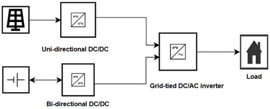
Figure 1.
Block schematic of the hybrid PV–battery system.
The PV array interfaces with the DC bus through a unidirectional DC/DC converter, while the battery connects via a bidirectional DC/DC converter for charging and discharging. A unidirectional DC/AC converter links the DC bus to the load/grid, ensuring regulated AC power delivery.
3. GWO-PSO and EMS Algorithm
The hybrid GWO–PSO algorithm combines two optimization strategies: PSO for efficient local exploitation and GWO for global exploration. Both components operate in parallel rather than sequentially, enabling the algorithm to maintain a strong balance between exploration and exploitation during the optimization process. In the GWO part of the algorithm, the distance vectors from the current agent to the three leading wolves (, , ) are expressed as []
Here, is the current agent position, are the positions of the best three wolves, are random coefficient vectors, and is the inertia weight. Candidate positions are then updated according to
In parallel, the PSO component refines the solutions by updating particle velocities as follows:
where is the velocity of the particle at iteration is its position, are random numbers uniformly distributed in [0, 1], and are acceleration coefficients. The terms represent the positions of the best wolves (, β, δ).
The coefficient the GWO equations is defined as
where and decreases linearly from 2 to 0 during the iterations.
When , the search agents move away from the best leaders (), promoting exploration of new regions of the search space. When , the agents converge toward these leaders, enhancing exploitation around the best solutions. This adaptive mechanism enables the hybrid GWO–PSO to transition smoothly from global exploration to local exploitation, refining the optimal and values that minimize the ITAE and maintain stable DC-bus voltage (≈800 V) with SOC within 20–80% [].
The objective of the optimization process is to tune the PI controller gains to ensure stable DC-bus voltage regulation and reliable power sharing between the PV array, battery, and grid. The performance of each candidate solution is evaluated using the Integral of Time-weighted Absolute Error (ITAE) criterion [].
The objective function (ITAE) in Equation (20) is continuous with respect to and . Although nonconvex due to system nonlinearities, the adaptive coefficient ensures balanced exploration and exploitation. This mechanism, combined with PSO’s velocity refinement, enables stable and consistent convergence without requiring convexity.
Subject to the following error components that describe the deviation between reference and measured system variables:
The total error is given as
Here, ITAE represents the time-weighted integral of the absolute error; denotes the instantaneous difference between reference and actual system values; is the total simulation time; is the number of error terms. and represent the reference and actual DC-bus voltages, and denote the reference and actual load currents, and are the reference and measured battery currents, and and correspond to the reference and actual supercapacitor (or short-circuit) currents. is the virtual droop resistance applied to maintain proportional current sharing.
This formulation allows the optimization algorithm to minimize all relevant control errors across the PV, battery, and grid paths simultaneously. Compared with other indices such as ISE or IAE, ITAE emphasizes errors that persist over time, improving transient response and achieving faster settling and smoother control of the DC bus.
This EMS optimizes the proportional and integral controller gains () of the bidirectional converter shown in Figure 2.
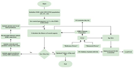
Figure 2.
Flowchart of the EMS–GWO–PSO optimization process.
Each agent in the Hybrid GWO–PSO population represents a candidate pair of these gains, which are iteratively tuned to minimize the ITAE index defined in Equation (20).
The optimization process evaluates the fitness of each pair based on voltage and current deviations across the PV, battery, and grid paths.
The search space of the controller gains is confined within the range
As reported in [], this procedure ensures that the tuned values remain within physically meaningful limits while achieving minimal ITAE and smooth DC-bus regulation.
In addition, the controller gain search space was constrained within and , based on preliminary tuning and consistent with the optimized values summarized in Table 3. These limits, along with the SOC (20–80%) and converter power constraints defined in Equations (2)–(5), ensure physically meaningful and stable operation throughout the optimization.

Table 3.
Comparison of PSO, GWO, and Hybrid GWO-PSO PI Controllers.
3.1. Dual-Loop Control Algorithm
The proposed control scheme adopts a dual-loop configuration similar to that in []. The fast loop executes the converter’s PI-based voltage and current regulation at a switching frequency of 10 kHz (control step ≈ 1 × 10⁻⁴ s), ensuring stable DC-bus voltage and precise current sharing among the PV, battery, and grid converters. The slow loop represents the hybrid GWO–PSO, which adjusts the controller gains using the mathematical relations defined in Equations (9)–(20). After each 0–3 s transient window, the optimizer evaluates the ITAE objective and updates the parameters of the fast loop accordingly. Equations (11)–(13) describe the computation of distance vectors between each search agent and the three leading wolves (, , ). These relations determine how every agent moves toward or away from the current best solutions, balancing the global exploration of the search space and local refinement. Equations (14)–(16) generate three potential updated positions based on the leaders’ guidance and the scaling coefficients , , and . The values of these coefficients define whether the wolves explore new areas () or exploit promising regions (). Equation (17) produces the final position of each agent by averaging the three candidate positions derived from the α, β, and δ wolves. Achieves acceptable regulation but exhibits a slower transient response and minor steady-state oscillations.
This averaging ensures a balanced search direction and prevents premature convergence. Equation (18) introduces the PSO-based velocity refinement that operates in parallel with the GWO phase. Each agent’s velocity and position are adjusted according to its distance from the leaders, adding momentum and improving local exploitation. This hybridization accelerates convergence while avoiding local minima. Equation (19) defines the adaptive coefficient , where linearly decreases from 2 to 0 throughout the iterations. This dynamic coefficient governs the transition between exploration at early stages and exploitation near convergence. The optimization was executed for 10 iterations, which was sufficient for convergence and stable controller tuning without excessive computational load. The performance of each candidate solution is assessed using the Integral of Time-Weighted Absolute Error expressed in Equation (20). The ITAE combines the time-weighted voltage and current errors at the PV, battery, and DC-bus levels. Minimizing this objective ensures faster settling time, smaller overshoot, and smoother converter operation under dynamic conditions. The agent producing the minimum ITAE identifies the optimal and gains. These gains are automatically written to the PI controllers in the fast loop via the MATLAB Function interface, allowing continuous operation while the optimizer refines control performance. This dual-loop control algorithm maintains real-time voltage regulation through the inner loop and adaptive optimal tuning through the outer loop, extending the approach introduced in [] to the grid-connected PV–battery system.
3.2. EMS and Hybrid GWO-PSO Flowchart Dual-Loop Control Structure
The EMS–GWO–PSO flowchart, as shown in Figure 2, starts with initializing the EMS using a GWO–PSO population (x1, x2, xn) and setting control parameters (a, A, C) for the optimizer. The fitness evaluation phase measures the difference between reference and actual power from the PV–battery system, processed through the EMS fitness function. This function aims to minimize conversion losses, improve dynamic response during transitions, and align with load dynamics and overall power balance. Based on this error assessment, potential PI controller parameters (Kp, Ki) are evaluated, and performance feedback is sent to the optimizer. The GWO–PSO algorithm iteratively adjusts agent positions using GWO equations and PSO velocity updates, recalculating fitness values and refining solutions until the maximum iterations are reached. Once the stopping criterion is met, the optimal PI controller gains are identified and implemented in the bidirectional DC/DC converter, managing power exchange between the PV–battery system and the load/grid. This coordinated approach ensures stable DC bus voltage, regulated battery operations, and reliable grid support under varying conditions.
In summary, the proposed EMS employs a dual-loop architecture integrating real-time PI control and hybrid GWO–PSO. The fast inner loop, defined by Equation (5), operates at a high switching frequency of 10 kHz (control step ≈ 1 × 10⁻⁴ s) to regulate battery current and DC-bus voltage according to the power balance and SOC limits given in Equations (1)–(4). The slow outer loop executes the hybrid optimization every 0.3–0.5 s, minimizing the ITAE performance index in Equation (20) to refine the proportional and integral gains within their feasible operating limits. After each transient cycle, the optimizer determines the optimal parameters and , which are automatically updated in the fast loop via the MATLAB Function interface. This interaction allows the inner loop to maintain real-time voltage stability while the outer loop continuously enhances controller performance, resulting in faster convergence, shorter settling time, and smoother voltage regulation under varying PV generation and load conditions.
4. Results and Discussion
System power balance, SOC dynamics, and operational constraints are governed by Equations (1)–(5), ensuring safe and reliable energy exchange among the PV, battery, and grid. The bidirectional converter is controlled using a cascaded PI structure: an inner current loop for accurate charge/discharge control Equation (7) and an outer voltage loop for DC-bus regulation Equation (8). The proportional and integral gains are optimized in real time using the Hybrid GWO–PSO algorithm, which minimizes the ITAE performance index Equation (20) to reduce overshoot, improve settling time, and enhance the system’s dynamic response under fluctuating conditions. A 3 s simulation was performed to capture transient behaviour. During 0–1.5 , PV generation and load demand created a power deficit, prompting grid import; at 1.5 , increased irradiance enabled a smooth transition to export mode coordinated by the EMS–GWO–PSO controller. The hybrid optimization maintained the DC-bus voltage near 800 V and reduced converter losses, ensuring rapid equilibrium between the PV, battery, and grid subsystems. Compared with previous studies [,], the proposed method extends hybrid metaheuristic optimization to grid-connected PV–battery systems and demonstrates superior voltage regulation, faster convergence, and improved reliability during PV-generation and load fluctuations, the results confirm that the strategy delivers faster and more reliable transitions between import and export while reducing unnecessary losses. The optimized PI gains and performance indices for all three algorithms are summarized in Table 3.
The hybrid GWO-PSO controller was selected because it achieved faster convergence, shorter settling time, and smaller overshoot compared with PSO and GWO.
As shown in Section 4.8 (battery voltage), both PSO and GWO produced similar responses with slow stabilization, while the hybrid method reached steady operation more quickly and with less fluctuation. This demonstrates that the hybrid optimizer provides smoother grid power exchange and improved voltage stability in the PV-battery-grid system.
Recent studies also show growing interest in hybrid metaheuristic control for renewable systems. Similar GWO–PSO frameworks have been applied in PV–battery setups to achieve faster convergence and improved dynamic response [,,,]. The results of this work align with these trends, confirming the effectiveness of the hybrid EMS–GWO–PSO approach for real-time coordination.
4.1. Power Balance in PV System
The overall system power balance is evaluated using Equation (27) and Figure 3 illustrates the PV, grid, battery, and load powers at the point of common coupling (PCC).
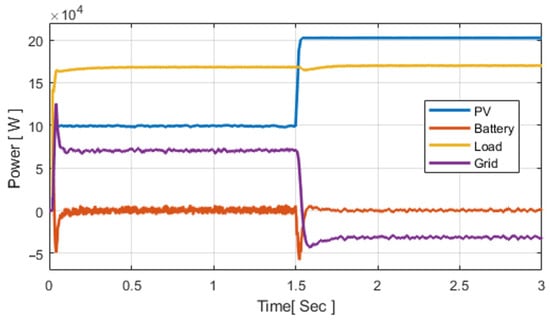
Figure 3.
The energy balance of the system evaluated using the power balance principle using Equation (27).
At 1.5 s, the balance yields approximately zero 20 kW, and kW. Thus, , equating to 2.5% of . Ideally, the balance should be zero; any deviation reflects conversion dynamics and control limitations. Similar small deviations have been reported in other PV–battery grid studies [,,,,]. The system power balance is validated, showing close agreement between PV generation, grid exchange, battery power, and load demand, with only ~2.5% deviation due to converter and control dynamics, similar to the balance reported by Chakir et al. [] and Amar et al. []. This rapid and smooth exchange between import and export confirms the hybrid controller’s superior coordination and dynamic performance in managing power interaction.
4.2. Three-Phase Currents
The inverter output currents are used to verify waveform quality and EMS tracking. Figure 4 illustrates the three-phase currents during the EMS–GWO transition.
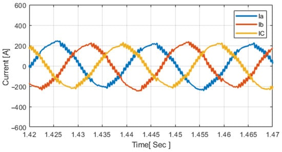
Figure 4.
Inverter three-phase output currents under EMS–GWO control.
The three-phase currents remain sinusoidal, balanced, and phase-shifted by 120° throughout the simulation, confirming stable EMS tracking and high-quality waveform regulation under GWO-based control. Figure 4 confirms that the inverter output currents remain balanced, and 120° apart during steady-state operation, consistent with the waveform stability demonstrated by Obaid et al. [].
4.3. Active/Reactive Inverter Power
The inverter active and reactive power responses are evaluated to verify EMS–GWO performance. Figure 5 illustrates the inverter output powers during the EMS transition.
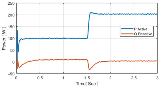
Figure 5.
Inverter active and reactive powers under EMS–GWO control.
At 1.5 s, the active power increases sharply while reactive power remains near zero, confirming stable operation. Similar inverter regulation with minimized reactive oscillations was reported by Srimati and Vijaykumar [] and validated in hybrid optimization studies by Nguyen and Nguyen [].
4.4. Grid Active and Reactive Power
Grid power exchange at the PCC is used to validate grid support behaviour. Figure 6 shows the active and reactive power flows under EMS–GWO operation.
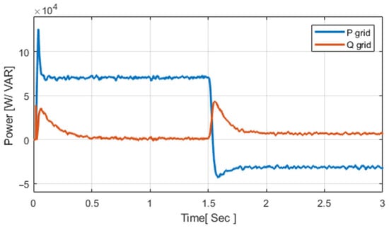
Figure 6.
Grid active and reactive power at the PCC.
Initially, the grid drew approximately 6.7 kW, with reactive power measured below 0.6 kVAR. When the EMS–GWO controller engaged at 1.5 s, the power flow shifted to an export of around –4.8 kW, while the reactive power remained nearly zero. A similar import-to-export transition was reported by Yaqoob et al. [], who implemented a comparable GWO-based energy management strategy. In contrast, Al-Tameemi et al. [] employed a PSO–GWO hybrid method, achieving stable power regulation but with a longer settling time of approximately 0.5 s. The present system, however, stabilizes within roughly 0.2 s, demonstrating a faster dynamic response, reduced transient oscillations, and improved energy exchange stability at the PCC. In a nutshell, the system shows a rapid and stable transition from import to export with minimal delay and nearly zero reactive power, highlighting the EMS–GWO controller’s superior response and smoother energy exchange compared with previous methods.
4.5. Daily Load and PV Pattern
Forecast-based daily load and PV generation profiles are used for EMS scheduling. Figure 7 presents the 24 h demand and PV generation curves with variability added to simulate cloud fluctuations.
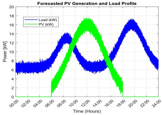
Figure 7.
Daily load forecast and PV generation profile for EMS scheduling.
Based on the forecasting approach of Alam et al. [], daily load and PV generation profiles were calculated over 24 h. The load shows a base of 6–7 kW, with peaks of ~13 kW in the morning and ~17.5–18 kW in the evening. PV generation is limited to 06:00–18:00, reaching ~15–16 kW at midday. Random noise was added to the PV profile to represent cloud fluctuations. This daily cycle clearly shows the peak hours, and the information can be used to optimize battery operation and reduce costs under time-of-use (TOU) pricing. The mismatch between load demand 6–18 kW and daylight-only PV generation confirms the necessity of energy storage and proper scheduling, as supported by Wamalwa et al. [] and Muriithi et al. [].
4.6. Power Battery
The battery response under EMS–GWO operation is shown in Figure 8.
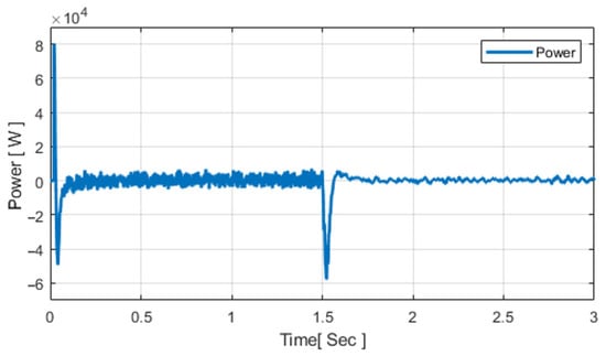
Figure 8.
Battery power response under EMS–GWO control.
Figure 8 illustrates the battery’s role in balancing power flow. It charges at approximately +5 kW before 1.5 s and discharges at around –5 kW afterward to support the load. The brief transient at 1.5 s results from normal inverter switching and does not affect system stability, unlike the slower recovery reported by Obaid et al. []. The battery’s electrical response under EMS–GWO operation is illustrated in Figure 9 showing both DC bus voltage and battery current waveforms.

Figure 9.
Battery response under EMS–GWO control: (a) DC bus voltage, (b) battery current.
Battery voltage and current response are shown during a PV power step at 1.5 s. The DC bus voltage remains stable at ~800 V, while the battery current shifts from light discharge to charging. A short transient spike is observed at the step event, reflecting inverter and converter switching dynamics. After this, the battery absorbs surplus PV power smoothly, and the system returns to steady operation. Comparable studies confirm similar behaviour: Srimathi and Vijaykumar [] reported stable DC bus regulation in PV–battery microgrids during sudden disturbances; Assiene Mouodo et al. [] highlighted that accurate SOC estimation ensures reliable current transitions; and Nguyen and Nguyen [] showed that hybrid PSO–GWO enhances voltage stability in smart grids. These observations support the robustness observed in both voltage and current waveforms in this work. In addition, Srimathi and Vijaykumar [] also demonstrated consistent voltage stability in DC microgrids under switching events, while Vaidya et al. [] confirmed effective current control in EV–PV charging systems, and Nguyen and Nguyen [] reported that PSO–GWO reduces oscillations and improves transient response. The present study not only matches well with these outcomes but also achieves faster settling and smoother current dynamics.
4.7. State of Charge
The impact of EMS–GWO on battery SOC is shown in Figure 10.
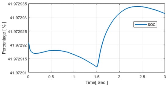
Figure 10.
SOC profile of the lithium-ion battery under EMS–GWO operation.
Figure 10 shows the SOC profile of the Lithium-ion battery during a 3 s simulation. The battery was parameterized with a nominal voltage of 745 V and a rated capacity of 1500 Ah, corresponding to an energy capacity of approximately 745 kWh. The initial SOC was set to 40%, representing a realistic condition in which the battery had been discharged overnight to support local demand before sunrise. The SOC variation is governed by Equation (28):
where denotes the charging or discharging power in watts, the elapsed time in seconds, the nominal voltage in volts, and the rated capacity in ampere-hours.
The factor 3600 is used to convert ampere-hours into coulombs (1 Ah = 3600 C), ensuring unit consistency in SOC integration. Due to the large battery capacity (1000 Ah), a power exchange of 5 kW over 3 s results in only a 0.002% change in SOC. As a result, the SOC remains nearly constant at about 41.97%, with a brief dip around 1.5 s when the battery is momentarily discharged to support the load during the EMS switching event. It then rises slightly as PV generation increases and charging resumes. Comparable SOC-based control principles have been reported in [], where SOC constraints (20–90%) were incorporated into a hybrid PSO–GA energy-management strategy for a PV/Wind/Battery/Diesel microgrid to maintain energy balance and extend battery lifetime. Likewise, accurate SOC estimation for centralized battery-management systems in solar-powered EV-charging stations has been emphasized in [], where SOC tracking was shown to enhance voltage stability and ensure efficient charge–discharge coordination.
4.8. Comparison of PSO, GWO, and Hybrid GWO–PSO Controllers
As shown in Figure 11a,b, the PSO and GWO controllers exhibit nearly the same performance, keeping the DC-bus voltage close to 800 V with an overshoot of approximately 1% and a settling time of about 0.2 s. Conversely, in Figure 11b, the Hybrid GWO–PSO demonstrates significantly quicker stabilization, achieving a settling time of 0.05 s with minimal overshoot, thereby illustrating a more refined and stable voltage regulation.
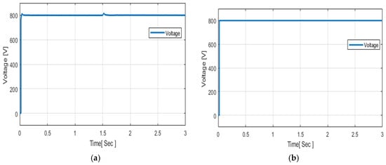
Figure 11.
Battery-voltage response under (a) PSO and GWO, and (b) Hybrid GWO–PSO control.
As summarized in Table 3, the hybrid GWO–PSO controller achieved superior overall performance compared with the individual PSO and GWO methods. Although both PSO and GWO maintained acceptable voltage regulation as reported in []. The PSO algorithm required a considerably longer simulation and convergence time because of its limited global search capability, consistent with observations reported by Al-Tameemi et al. []. By contrast, the hybrid GWO–PSO algorithm effectively integrates PSO’s local exploitation strength with GWO’s global exploration capacity, enabling faster convergence toward the optimal and parameters. This results in improved voltage stability, reduced overshoot, and smoother transient response under varying load and PV-generation conditions.
Therefore, the hybrid GWO–PSO was selected for the proposed EMS due to its faster convergence rate, shorter settling time, and greater robustness compared with PSO and GWO alone.
Table 4 presents a comparative summary of related work, outlining the main system configurations, objectives, and EMS approaches used in previous studies.

Table 4.
Comparative study of related work.
5. Conclusions and Future Trends
This research introduced an EMS–GWO–PSO framework designed for a grid-connected PV–battery system, which integrates rapid real-time control with slower optimization scheduling. The hybrid GWO–PSO algorithm was selected over standalone GWO and PSO methods to overcome slow convergence and local stagnation, ensuring faster tuning and improved control precision. The results demonstrate stable inverter functionality, seamless bidirectional interaction with the grid, and dependable battery dynamics, with the state of charge (SOC) consistently maintained within the 20–80% range. The suggested system effectively minimized power losses, enhanced transient responses during transitions among the PV, battery, and grid, and adjusted its export strategy according to daily load and PV forecasts while maintaining overall power equilibrium. These results substantiate the dual-loop EMS–GWO–PSO methodology as a proficient and resilient solution for hybrid low-voltage systems.
Future research will aim to incorporate actual load and PV-generation data to improve forecasting precision and align EMS scheduling with real daily cycles. The integration of time-of-use (TOU) electricity pricing alongside real-time forecasts could further refine battery charging and discharging processes, thereby decreasing grid imports during peak periods and enhancing cost-effectiveness. Additional avenues for exploration include the development of hybrid EMS strategies that merge reinforcement learning with metaheuristics for adaptive scheduling, as well as performing hardware-in-the-loop or digital real-time validation to confirm practical performance. Ultimately, the incorporation of supplementary storage technologies such as supercapacitors or flow batteries, along with the extension of the framework to community microgrids featuring electric vehicle charging, would facilitate flexible, resilient, and sustainable operations within future distribution networks.
Author Contributions
Methodology, Y.I.R.A. and K.P.; Software, Y.I.R.A. and Z.H.A.A.-T.; Validation, Y.I.R.A.; Formal analysis, Y.I.R.A. and K.P.; Investigation, Y.I.R.A. and K.P.; Resources, K.P.; Data curation, Y.I.R.A. and Z.H.A.A.-T.; Writing—original draft, Y.I.R.A.; Writing—review & editing, K.P., J.K. and T.T.L.; Supervision, K.P. and J.K.; Project administration, K.P. and J.K. All authors have read and agreed to the published version of the manuscript.
Funding
This research received no external funding.
Data Availability Statement
The original contributions presented in this study are included in the article. Further inquiries can be directed to the corresponding author.
Conflicts of Interest
The authors declare no conflict of interest.
References
- Chakir, A.; Tabaa, M.; Moutaouakkil, F.; Medromi, H.; Julien-Salame, M.; Dandache, A.; Alami, K. Optimal energy management for a grid-connected PV–battery system. Energy Rep. 2020, 6, 218–231. [Google Scholar] [CrossRef]
- Amar, G.; El-Madjid, B.; Abdelaziz, T. Optimal control and energy management of grid-connected PV-diesel-battery hybrid power system. In Proceedings of the 2019 International Conference on Advanced Electrical Engineering, ICAEE 2019, Algiers, Algeria, 19–21 November 2019. [Google Scholar] [CrossRef]
- Yaqoob, S.J.; Arnoos, H.; Qasim, M.A.; Agyekum, E.B.; Alzahrani, A.; Kamel, S. An optimal energy management strategy for a photovoltaic/li-ion battery power system for DC microgrid application. Front. Energy Res. 2023, 10, 1066231. [Google Scholar] [CrossRef]
- Al-Tameemi, Z.H.A.; Lie, T.T.; Foo, G.; Blaabjerg, F. Optimal Coordinated Control of DC Microgrid Based on Hybrid PSO–GWO Algorithm †. Electricity 2022, 3, 346–364. [Google Scholar] [CrossRef]
- Chtita, S.; Motahhir, S.; El Hammoumi, A.; Chouder, A.; Soufiane Benyoucef, A.; El Ghzizal, A.; Derouich, A.; Abouhawwash, M.; Askar, S.S. A novel hybrid GWO–PSO-based maximum power point tracking for photovoltaic systems operating under partial shading conditions. Sci. Rep. 2022, 12, 10637. [Google Scholar] [CrossRef] [PubMed]
- Indumathi, R.; Lakshmanan, S.A.; Siong Chin, C. Comparative Analysis of Hybrid GA PSO and GWO PSO MPPT Algorithm for Photovoltaic Systems. In Proceedings of the 2024 IEEE 3rd International Conference on Electrical Power and Energy Systems (ICEPES), Bhopal, India, 21–22 June 2024; pp. 1–6. [Google Scholar] [CrossRef]
- Ibrahim, A.-W.; Xu, J.; Al-Shamma’a, A.A.; Farh, H.M.H.; Aboudrar, I.; Oubail, Y.; Alaql, F.; Alfraidi, W. Optimized Energy Management Strategy for an Autonomous DC Microgrid Integrating PV/Wind/Battery/Diesel-Based Hybrid PSO-GA-LADRC Through SAPF. Technologies 2024, 12, 226. [Google Scholar] [CrossRef]
- Ahmed, H.S.; Abid, A.J.; Obed, A.A.; Saleh, A.L.; Hassoon, R.J. Maximizing Energy Output of Photovoltaic Systems: Hybrid PSO GWO CS Optimization Approach. J. Tech. 2023, 5, 174–184. [Google Scholar] [CrossRef]
- Bhadoria, U.S.; Tiwari, P.N.; Thakre, K. Solar PV Parameter Extraction Using GWO PSO Algorithm. In Proceedings of the 2024 International Conference on Sustainable Power and Energy (ICSPE), Bhopal, India, 28–29 November 2024; pp. 1–6. [Google Scholar] [CrossRef]
- Wamalwa, F.; Ishimwe, A. Optimal energy management in a grid-tied solar PV-battery microgrid for a public building under demand response. Energy Rep. 2024, 12, 3718–3731. [Google Scholar] [CrossRef]
- Alam, M.M.; Rahman, M.H.; Ahmed, M.F.; Chowdhury, M.Z.; Jang, Y.M. Deep learning based optimal energy management for photovoltaic and battery energy storage integrated home micro-grid system. Sci. Rep. 2022, 12, 15133. [Google Scholar] [CrossRef] [PubMed]
- Obaid, D.S.; Mahdi, A.J.; Alkhafaji, M.H. Optimal energy management of a photovoltaic-batteries-grid system. Indones. J. Electr. Eng. Comput. Sci. 2022, 27, 1162–1175. [Google Scholar] [CrossRef]
- Muriithi, G.; Chowdhury, S. Optimal energy management of a grid-tied solar PV-Battery microgrid: A reinforcement learning approach. Energies 2021, 14, 2700. [Google Scholar] [CrossRef]
- Gupta, M.; Tiwari, P.M.; Viral, R.K.; Shrivastava, A.; Zneid, B.A.; Hunko, I. Grid-connected PV inverter system control optimization using Grey Wolf optimized PID controller. Sci. Rep. 2025, 15, 28869. [Google Scholar] [CrossRef] [PubMed]
- Abera, A.G.; Yetayew, T.T.; Alyu, A.B. Optimized solar PV integration for voltage enhancement and loss reduction in the Kombolcha distribution system using hybrid grey wolf–particle swarm optimization. Results Eng. 2025, 26, 105484. [Google Scholar] [CrossRef]
- Ibrahim, A.-W.; Farh, H.M.H.; Al-Shamma’a, A.A. A Comprehensive Review of MPPT Strategies for Hybrid PV–TEG Systems: Advances, Challenges, and Future Directions. Mathematics 2025, 13, 2900. [Google Scholar] [CrossRef]
- Jain, A.; Nagar, S.; Singh, P.K.; Dhar, J. A hybrid learning-based genetic and grey-wolf optimizer for global optimization. Soft Comput. 2023, 27, 4713–4759. [Google Scholar] [CrossRef]
- Mirjalili, S.; Mirjalili, S.M.; Lewis, A. Grey wolf optimizer. Adv. Eng. Softw. 2014, 69, 46–61. [Google Scholar] [CrossRef]
- Nguyen, T.L.; Nguyen, Q.A. A Multi-Objective PSO-GWO Approach for Smart Grid Reconfiguration with Renewable Energy and Electric Vehicles. Energies 2025, 18, 2020. [Google Scholar] [CrossRef]
- Srimathi, V.; Vijayakumar, D. Design and Implementation of Power Management System in Multi string Solar-Interfaced DC Microgrid with Energy Storage System. IEEE Access 2025, 13, 140012–140027. [Google Scholar] [CrossRef]
- Assiene Mouodo, L.V.; Axaopoulos, P.J. Optimization and Estimation of the State of Charge of Lithium-Ion Batteries for Electric Vehicles. Energies 2025, 18, 3436. [Google Scholar] [CrossRef]
- Vaidya, S.; Prasad, K.; Kilby, J. To Study the Impact of Rooftop Solar-Powered EV Charging Stations on Distribution Network Efficiency: Challenges and Solutions. In Proceedings of the 2025 IEEE Region 10 Symposium (TENSYMP), Christchurch, New Zealand, 7–9 July 2025; pp. 1–8. [Google Scholar] [CrossRef]
- Mammeri, E.; Yahya, H.; Kherfane, R.; Youssef, M.K.; Guessoum, A. A hybrid GWO PSO algorithm for global MPP tracking in PV systems under PSCs. In Proceedings of the 2023 International Conference on Energy Transition and Security (ICETS), Ghardaïa, Algeria, 12–14 December 2023; pp. 1–6. [Google Scholar] [CrossRef]
Disclaimer/Publisher’s Note: The statements, opinions and data contained in all publications are solely those of the individual author(s) and contributor(s) and not of MDPI and/or the editor(s). MDPI and/or the editor(s) disclaim responsibility for any injury to people or property resulting from any ideas, methods, instructions or products referred to in the content. |
© 2025 by the authors. Licensee MDPI, Basel, Switzerland. This article is an open access article distributed under the terms and conditions of the Creative Commons Attribution (CC BY) license (https://creativecommons.org/licenses/by/4.0/).