Abstract
Demand for brushless alternatives to the series universal motors and induction motors in domestic applications and automotive applications is increasing. Among the available candidates, single-phase flux-switching permanent magnet (SP-FSPM) machines have gained attention due to a simpler magnetic structure and control system. However, their torque density remains limited. Therefore, a SP doubly-fed FSPM (SP-DF-FSPM) machine is developed in this paper which features an additional set of armature windings on the rotor. By effectively utilizing the rotor slot area, the proposed SP-DF-FSPM machine enhances electrical loading and torque density while providing inherent fault-tolerant capability, a critical addition compared with conventional SP-FSPM machines. A comprehensive parameter-sensitivity analysis is conducted for a 10-stator-pole/10-rotor-tooth configuration to optimize key geometric parameters for the maximum torque and reliable self-starting operation. The electromagnetic performance of an optimized design is evaluated and compared against a conventional SP-FSPM machine. The results show that the SP-DF-FSPM machine can achieve a 24.75% higher torque output, improved efficiency, and enhanced power factors under the healthy condition. Moreover, the machine can deliver 63.5% and 36.0% torque when operating with only stator and rotor windings, respectively, demonstrating the fault-tolerant capability. Experimental validation via an SP-DF-FSPM prototype shows close agreement with simulation results.
1. Introduction
Series universal motors are a common, cost-effective choice for home appliances and power tools; they, along with other existing options like induction or switched-reluctance machines, are limited by torque density, lower efficiency, and durability issues [,,]. This has created a pressing need for high torque density, high efficiency, and reliable machine alternatives for these applications. Therefore, research has since progressed into permanent magnet (PM) machines, among which the stator-PM machines, such as doubly salient PM machines, flux-reversal PM machines, and flux-switching PM (FSPM) machines, have emerged as a compelling alternative [,,].
In recent years, FSPM machines have been extensively investigated as one of the most promising stator-PM topologies, owing to its high torque capability and compact structure []. Their key advantage is that PMs are embedded in the stator, which houses the windings as well, allowing for a simple, robust salient-pole rotor. Thus, this configuration merges the mechanical durability of SRMs with the high efficiency and power factor of PM machines. Nevertheless, a fundamental design constraint remains: the placement of magnets within the stator core significantly reduces the available slot area for windings, which limits torque density [,]. To increase the slot area, partitioned stator topologies are proposed in [,,] which separates the PMs. These partitioned stator machines have a double air gap, and the rotor is sandwiched between the stator components. This structure better utilizes the inner space of the machine, hence improving the torque density. However, this approach results in complicated machine structure and increase in manufacturing costs. Furthermore, enhancing the fault tolerance of FSPM machines for high-reliability applications often necessitates complex strategies such as increasing the number of phases, single-layer windings, or adding redundant windings [,,,,]. These solutions increase costs, control complexity, and inverter requirements. A double-armature configuration was later proposed for poly-phase FSPM machines to simultaneously enhance torque density and fault-tolerant capability []. By augmenting the conventional design by integrating an additional armature winding within the rotor slots, this configuration directly leverages the previously unused rotor slot area, thereby increasing the electrical loading, and hence the torque density. Furthermore, the dual-armature winding structure inherently provides fault tolerance, as the stator and rotor windings can operate independently, introducing a layer of operational redundancy. The dual-armature technique has also been successfully applied to other poly-phase stator-PM machines like flux-reversal machines [] and doubly salient machines [].
Given that poly-phase dual-armature FSPM machines generally require different numbers of stator poles and rotor teeth and hence two different phase numbers, their control systems become inherently complex and costly. In contrast, SP FSPM machines feature a simpler structure and control scheme, making them more suitable for cost- and reliability-sensitive consumer applications [,]. Despite these, SP FSPM machines suffer from relatively low torque density, poor starting capability, and phase redundancy. The self-starting capability can be improved by introducing the chamfered rotor tooth and segmented rotor tooth [], but the absence of an SP FSPM configuration capable of simultaneously achieving high torque density and fault tolerance remains evident.
To address this gap, this paper develops an SP doubly-fed (DF) FSPM (SP-DF-FSPM) configuration by employing dual-armature configurations. The effects and potential benefits of dual-armature configurations on the torque density and fault tolerance in SP FSPM machines are systematically investigated or quantified for the first time. In addition, analysis is conducted to investigate the influence of design parameters, including the unique rotor tooth chamfer size, on torque density. It should be noted that the requirement to maintain self-starting capability introduces additional design trade-offs during the conducted optimization, which distinguishes SP machines from their poly-phase counterparts. Torque outputs under healthy and faulty conditions, along with other electromagnetic performance, of the optimized SP-DF-FSPM machine are compared with the optimized conventional SP-FSPM machine to demonstrate the superiority.
In this article, initial topology and working principle of the SP-DF-FSPM machine are presented, followed by the sensitivity analysis of key parameters to maximize the torque while maintaining the starting torque capabilities. Afterwards, a detailed electromagnetic analysis is performed for the optimized machines, and their performance is compared. Finally, a 10-stator-pole/10-rotor-teeth SP-DF-FSPM machine was fabricated and tested for validation.
2. SP-DF-FSPM Machine Topology and Operating Principle
Common topologies of the conventional SP-FSPM and the proposed SP-DF-FSPM machines are presented in Figure 1. The proposed SP-DF-FSPM machine is derived from the conventional SP-FSPM configuration by introducing an additional set of armature windings. The two sets of armature windings in the SP-DF-FSPM machine are powered by separate inverters, allowing them to function both collaboratively and independently. Hereby, this feature adds fault-tolerant capability to the machine, as the remaining set of armature windings can continue to function even if one set fails. It is worth noting that the SP-FSPM machines in Figure 1a,b must comprise the same number of stator poles and rotor teeth, as opposed to poly-phase DF-FSPM machines in Figure 1c, which require different numbers of stator poles and rotor teeth []. Moreover, the rotor tooth chamfer is introduced to enhance self-starting capability, while poly-phase DF-FSPM machines can have symmetry tooth tips.
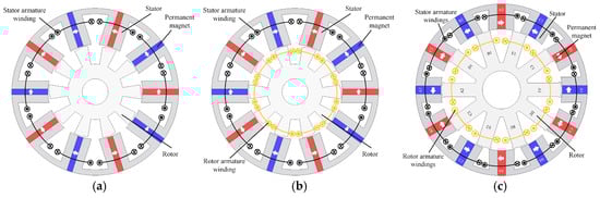
Figure 1.
FSPM machine topologies. (a) SP FSPM. (b) SP-DF-FSPM. (c) Poly-phase DF-FSPM.
The total torque of the SP-DF-FSPM machine mainly originates from two components: the interaction between the PM and stator armature (PM-stator armature) fields, and the interaction between the PM and rotor armature (PM-rotor armature) fields.
The PM-stator armature torque component is equivalent to that of the conventional SP-FSPM machine based on the flux-switching principle. The working principle and the corresponding flux linkage of the stator armature component are presented in Figure 2 and Figure 3. Flux linkage in the stator coil is zero when the rotor tooth is aligned with the PM (Figure 2a) or the stator slot (Figure 2c). When the rotor tooth aligns with either of the stator teeth (Figure 2b,d), positive or negative flux linkage is achieved. The stator coil flux varies with the rotation of the rotor, inducing back-EMFs.
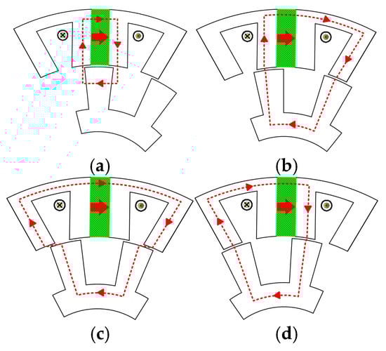
Figure 2.
Flux linkage states of the stator armature windings. (a) Zero. (b) Positive maximum. (c) Zero. (d) Negative maximum.
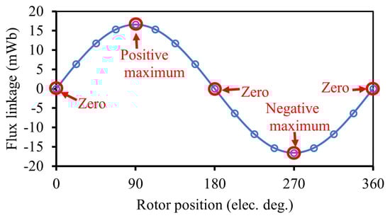
Figure 3.
Flux linkage of the stator armature winding.
The PM-stator armature interaction exhibits a similar manner to that of the interior PM machine. Rotor flux linkage is zero when the rotor tooth is aligned with the stator PM (Figure 4a,c). Positive and negative maximum flux linkage (Figure 4b,d) is obtained when the rotor tooth is aligned with the stator slot. Rotor rotation varies flux linkage (Figure 5), inducing back-EMFs in rotor armature windings.
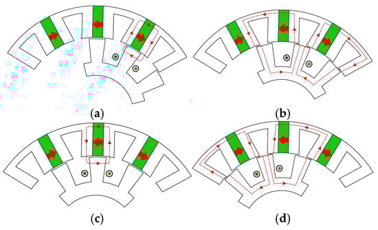
Figure 4.
Flux linkage states of the rotor armature windings. (a) Zero. (b) Positive maximum. (c) Zero. (d) Negative maximum.
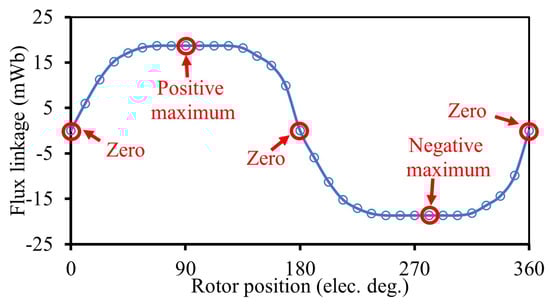
Figure 5.
Flux linkage of the rotor armature winding.
According to the explained working principle, the stator flux linkage waveform is periodic over one rotor tooth pitch, whereas the rotor flux linkage waveform repeats over two stator pole pitches. Therefore, the fundamental electrical frequencies of stator fs and rotor fr can be determined as:
and
where Ps and Pr are the number of stator poles and rotor teeth, respectively, and nr is the rotational speed of the rotor. For the SP-DF-FSPM machine having the same number of stator poles and rotor teeth, the rotor fundamental frequency is half of that of the stator fundamental frequency:
3. Parameter Sensitivity Analysis
In this section, parameter sensitivity analysis is carried out to maximize average torque, as well as the minimum starting torque for the proposed SP-DF-FSPM machine. For comparison, a conventional SP-FSPM machine is analyzed as well.
It should be noted that, different from three-phase FSPM machines, conventional SP machines also face a well-documented limitation in their self-starting capability. This is due to the presence of a “dead zone” at certain rotor positions where the starting torque is zero. Consequently, significant research has been devoted to mitigating this problem via geometric optimization of the machine’s rotor and stator to introduce magnetic asymmetry in the air gap, including the use of segmented or auxiliary rotors, the application of stator tooth chamfering, and the design of sub-rotors with non-uniform tooth widths.
To enhance the self-starting capability for the investigated design, the rotor tooth chamfer is employed. Figure 6 depicts the major geometric parameters of the SP-FSPM machine, and the initial parameters of the selected 10-stator-slot/10-rotor-slot SP-FSPM and SP-DF-FSPM machines are given in Table 1, where the total armature copper loss is set at 40 W. End effect is not considered during finite element analysis.
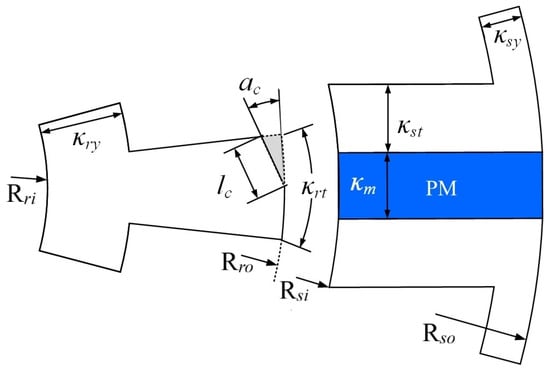
Figure 6.
Geometric parameter illustration.

Table 1.
Initial design specifications of SP-DF-FSPM and SP-FSPM machines.
3.1. Copper Loss Ratio
The electromagnetic performance of the SP-DF-FSPM machine is influenced by the distribution of copper losses between its stator and rotor windings. Analysis reveals that the average electromagnetic torque is maximized when the stator-to-rotor copper loss ratio is approximately 1.667, as Figure 7 shows.
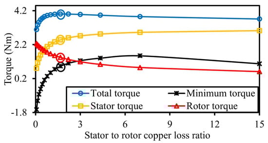
Figure 7.
Influence of stator to rotor copper loss ratio on average torque and minimum torque.
Since the SP-DF-FSPM machine can retain torque-producing capability even if one set of armature windings fails, the two aforementioned torque components are analyzed individually for fault-tolerant consideration. In an ideal scenario where the stator and rotor contribute equally to torque, approximately half of the rated torque could be maintained. However, a key constraint is the presence of dead zones in SP machines, rotor positions that yield negative torque. For instance, a copper loss ratio of 0.33 results in equal torque contribution from both windings and a total torque output of 90% of the maximum, but this configuration exhibits a negative minimum torque, rendering it susceptible to a dead zone. For self-starting capability and fault-tolerant operation, the stator and rotor windings contribute 62% and 36% of the torque, respectively, when keeping current in the healthy winding unchanged. It should be noted that the remaining small torque arises from the interaction of stator and rotor armature reaction fields, accounting for the slight deviation from 100% total torque contribution.
3.2. Split Ratio
The average torque in both SP-DF-FSPM and SP-FSPM machines exhibits a strong dependence on the split ratio, as Figure 8 demonstrates. A higher split ratio increases the flux linkage but simultaneously reduces the stator slot area in both machine types. This reduction in slot area results in a decrease in the stator armature current under a fixed copper loss. In the SP-DF-FSPM machine, however, the rotor armature current demonstrates a contrasting trend, increasing with the split ratio due to the expansion of the rotor slot area. This increase in rotor current enhances the electromagnetic torque produced by the PM-rotor-armature interaction. Consequently, the SP-DF-FSPM machine has a higher optimal split ratio compared to the SP-FSPM machine.
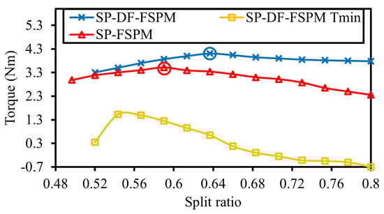
Figure 8.
Influence of split ratio on torque.
Furthermore, while wider PMs introduced by larger split ratio can boost the average torque, it also amplifies cogging torque and torque ripple, which can produce a negative minimum torque. Hence, although torque is similar when the split ratio is larger than 0.64 for the SP-DF-FSPM machine, the minimum starting torque drops dramatically and thereby impair the self-starting capability.
3.3. Magnet Arc
Figure 9 depicts the relationship between the magnet arc and the average torque. Increasing the magnet arc enhances the PM flux but simultaneously reduces the stator slot area, thus limiting the stator armature current. It is noteworthy that, in the SP-DF-FSPM machine, the rotor slot area and consequent rotor armature current remain unaffected by this geometric variation. The wider PMs increase flux linkages in the rotor coils and hence increases their electromagnetic torque contribution. Consequently, the SP-DF-FSPM machine is designed with a larger optimal magnet arc than the SP-FSPM machine. This design choice, however, can increase cogging torque and torque ripple. Similarly to the influence of the split ratio, the increased magnet arc negatively affects the minimum torque.
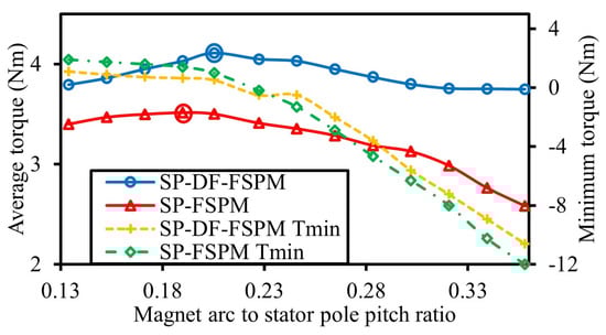
Figure 9.
Influence of magnet arc on torque.
3.4. Stator Tooth Arc
Figure 10 illustrates the influence of stator tooth arc on the average torque for both SP-DF-FSPM and SP-FSPM machine topologies. Enlarging the stator tooth arc reduces magnetic reluctance and alleviates saturation in the stator tooth, thereby enhancing the PM flux linkage. However, this geometric variation simultaneously reduces the stator slot area, which limits the armature current. In the SP-DF-FSPM machine, the resultant increase in the PM flux linking the rotor coils increases the torque produced by the PM-rotor-armature part. This additional torque contribution enables the SP-DF-FSPM machine to operate effectively with a slightly larger optimal stator tooth arc than its SP-FSPM counterpart. In terms of the minimum torque, it maintains a positive value when the stator tooth arc is larger than the 0.29, the optimal value for the maximum average torque.
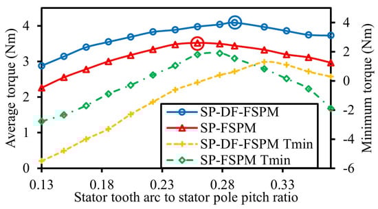
Figure 10.
Influence of stator tooth arc on torque.
3.5. Rotor Tooth Arc
As shown in Figure 11, the average torque exhibits a non-monotonic relationship with the rotor tooth arc, increasing to a maximum before declining. The optimal rotor tooth arcs are 0.47 and 0.49 of the rotor tooth pitch for the SP-DF-FSPM and SP-FSPM machines, respectively. Initially, a larger rotor tooth arc increases the overlapping area with the stator teeth, thereby reducing the air-gap reluctance. This reduction enhances the PM flux and consequently the average torque. Beyond a critical point, however, a further increase in the rotor tooth arc causes significant flux leakage at the inner magnet surfaces and slot opening, which reduces the effective PM flux and results in a decline in torque. Additionally, in the SP-DF-FSPM machine, the rotor armature current is also affected by the rotor tooth arc due to the resultant changes in rotor slot area.
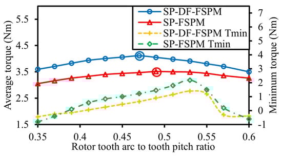
Figure 11.
Influence of rotor tooth arc on torque.
3.6. Stator Yoke Thickness
A reduced magnetic flux passes through the yoke in comparison to the stator tooth, which is reflected in the lower flux density. Therefore, the design necessitates a stator yoke thickness that is less than the stator tooth width. As the stator yoke thickness increases, the reduction in reluctance results in a slight increase in the PM flux. Nevertheless, it also leads to smaller stator slots and hence reduced stator currents. As illustrated in Figure 12, the torques of both the SP-FSPM and DF-SP-FSPM machines only increase a bit but then decline markedly. Therefore, the respective optimal yoke thicknesses for the SP-DF-FSPM and SP-FSPM machines are determined to be approximately 0.6 and 0.7 times the stator tooth width. This design optimizes flux densities and maximizes the stator slot area.
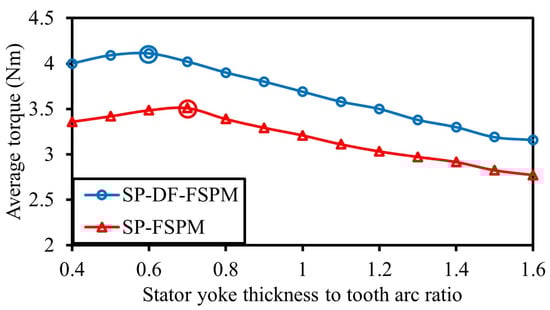
Figure 12.
Influence of stator yoke thickness on average torque.
3.7. Rotor Yoke Thickness
As illustrated in Figure 13, the average torque of the SP-FSPM machine remains largely unaffected by rotor yoke thickness, except under extreme geometric conditions. An excessively narrow yoke increases the saturation and reluctance, while an overly thick yoke reduces stator flux linkage and increases flux leakage. In contrast, the average torque of the SP-DF-FSPM machine exhibits a pronounced sensitivity to rotor yoke thickness due to its direct influence on the rotor armature current. Consequently, the optimal rotor yoke thickness for the SP-DF-FSPM machine is approximately 0.6 times the rotor tooth dimension, a value significantly less than that required for the SP-FSPM machine.
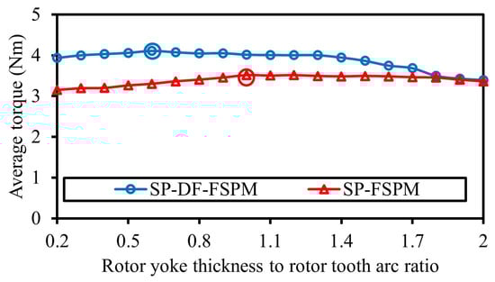
Figure 13.
Influence of rotor yoke thickness on average torque.
3.8. Rotor Tooth Chamfer
The rotor tooth chamfer is essential for the self-starting capability of SP FSPM machines, which creates an asymmetrical air gap, resulting in varying air-gap reluctance from one side of the rotor teeth to the other. This variation ensures the unidirectional rotation of the machine. The variations in average torque and minimum torque with the chamfer length lc and chamfer angle ac for both the SP-DF-FSPM and SP-FSPM machines is demonstrated in Figure 14. Tave_a and Tmin_a represent the average and minimum torque at chamfer angle ac, while Tave_l and Tmin_l represent the average and minimum torque at chamfer length lc. From Figure 14, it can be seen that the average torques decrease as the chamfer area gets larger, but the variation is not significant. However, for the minimum torque, almost all combinations of the chamfer dimensions achieve a positive minimum torque for the SP-FSPM machine, while some of them result in a negative minimum torque in the DF-SP-FSPM machine. Therefore, the chamfer dimensions are more critical for DF-SP-FSPM machines and should be carefully chosen for the consideration of self-starting capability.
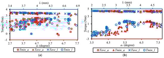
Figure 14.
Rotor teeth chamfer optimization for optimal torque performance. (a) SP-FSPM. (b) SP-DF-FSPM.
4. Electromagnetic Performance
This section presents a comparative analysis of the electromagnetic performance between the proposed SP-DF-FSPM machine and the conventional SP-FSPM machine. Both machines are optimized by a sequential optimization methodology to maximize the output torque. The process involved the iterative refinement of key geometric parameters, namely, the split ratio, magnet arc, stator tooth arc, stator yoke thickness, rotor tooth arc, rotor yoke thickness, and rotor tooth chamfer, where each subsequent parameter was optimized while holding previously adjusted parameters at their optimal values. The resulting optimal parameters are detailed in Table 2 and Figure 15. Discrepancies between the outcomes of this sequential approach and isolated optimizations arise from the strong interdependencies among these parameters. Notably, the optimal split ratio, stator tooth arc to stator pole pitch ratio, and rotor yoke thickness to rotor tooth arc ratio differ substantially between the SP-DF-FSPM and SP-FSPM topologies. However, the optimal ratios for stator yoke thickness to stator pole pitch, magnet arc to stator pole pitch, and rotor tooth arc to rotor tooth pitch are rather consistent across both machine types.
Table 2.
Optimized parameters of the SP-FSPM and SP-DF-FSPM machines.
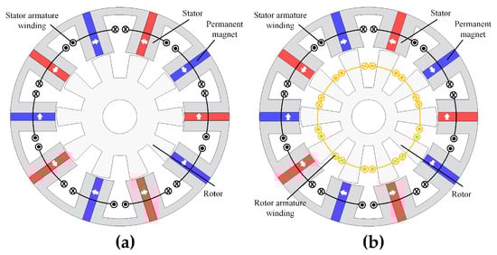
Figure 15.
Optimized machine geometries. (a) SP-FSPM. (b) SP-DF-FSPM.
4.1. Field Distribution and Back-EMF
Figure 16 depicts the no-load magnetic field distribution and flux densities for both configurations. A key geometrical distinction is evident, i.e., the SP-DF-FSPM machine employs a larger split ratio alongside a reduced rotor yoke thickness compared to the SP-FSPM machine. This configuration arises from the spatial requirement to accommodate both the stator winding and the additional rotor winding within the SP-DF-FSPM topology.
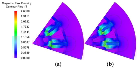
Figure 16.
No-load field distribution and flux density. (a) SP-FSPM. (b) SP-DF-FSPM.
Figure 17 illustrates the back EMF of the SP-DF-FSPM and SP-FSPM machines. The back EMF of the SP-FSPM and SP-DF-FSPM stators exhibits a comparable pattern. The stator back EMF resembles sinusoidal waves and exhibits high harmonic content, consisting of both even and odd harmonic components. Notably, there is a significant fifth harmonic that contributes to the torque ripple. Additionally, the rotor back EMF of the SP-DF-FSPM features prominent third, fifth, and ninth harmonic components.
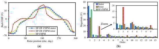
Figure 17.
Back EMFs of the SP-FSPM and SP-DF-FSPM machines. (a) Waveforms. (b) Spectra.
4.2. Inductance
A comparative analysis of self-inductances, presented in Figure 18, reveals that the stator self-inductance (Ls) is nearly identical for both the SP-DF-FSPM and SP-FSPM machines. Notably, within the SP-DF-FSPM topology, the stator self-inductance is observed to be greater than the rotor self-inductance (Lr). Furthermore, a distinct characteristic of the SP-DF-FSPM machine is the presence of magnetic coupling between its stator and rotor windings. However, the coupling is weak, so the average mutual inductance (Lsr) is nearly zero in Figure 18.
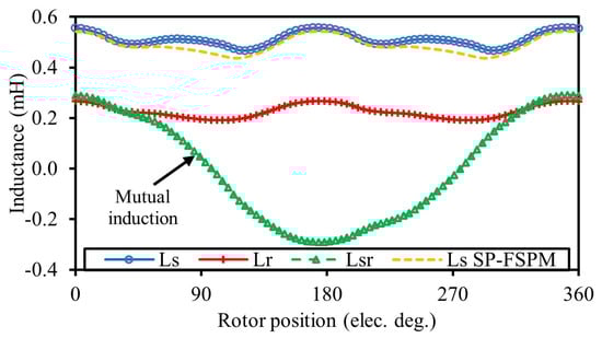
Figure 18.
Inductances of the SP-FSPM and SP-DF-FSPM machines.
4.3. Cogging Torque
Figure 19 presents a comparison of the cogging torque for the SP-DF-FSPM and SP-FSPM machines. When identical geometrical parameters are used, both machines exhibit equivalent cogging torque profiles, as their magnetic structures are inherently the same under open-circuit conditions. However, the optimized SP-DF-FSPM machine, with its final parameters detailed in Table 2, incorporates a larger rotor tooth arc and magnet arc than the SP-FSPM machine, resulting in a higher value of the cogging torque peak.
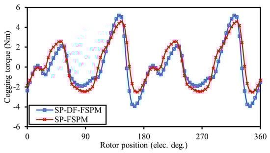
Figure 19.
Cogging torque of the SP-FSPM and SP-DF-FSPM machines.
4.4. On-Load and Fault-Tolerant Performance
Figure 20 illustrates the on-load magnetic field distribution and flux densities for both machine topologies operating under a fixed copper loss constraint of 40 W. The flux densities observed throughout the core structures remain below the material’s saturation threshold, approximately 1.85 T. Notably, the SP-DF-FSPM machine exhibits no discernible saturation despite its comparatively slimmer rotor yoke.
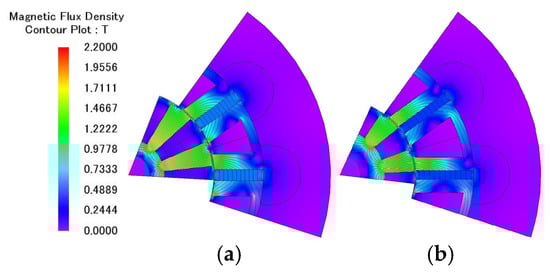
Figure 20.
On-load field distribution and flux density. (a) SP-FSPM. (b) SP-DF-FSPM.
Both stator and rotor armature components employ step load current. The SP-DF-FSPM machine achieves a 53% larger effective slot area, a result of the incorporation of rotor slots. This enhanced area allows higher electrical loading, thereby increasing the electromagnetic torque output for a given copper loss. Consequently, under load conditions, the SP-DF-FSPM machine produces an average torque approximately 24.75% greater than that of the conventional SP-FSPM machine. Moreover, the torque production per unit volume of PMs has increased by approximately 24.57%, showing cost-effectiveness. However, this increased torque is accompanied by a higher torque ripple, as detailed in Figure 21a and Table 3. Torque ripple is defined by
where Tmax, Tmin, and Tave are the maximum torque, minimum torque, and average torque, respectively.
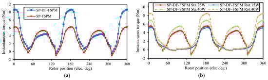
Figure 21.
Instantaneous torque waveforms of SP-FSPM and SP-DF-FSPM. (a) Normal condition. (b) Fault-tolerant.
Table 3.
Full-load torque comparison.
Under a single-armature winding fault condition, the SP-DF-FSPM machine maintains torque production through its healthy winding. When the healthy winding current is held constant, corresponding to 25 W stator and 15 W rotor copper loss, the resulting torque constitutes 63.5% (stator) and 36% (rotor) of the machine’s pre-fault output, equivalent to 78.91% and 45%, respectively, of the healthy SP-FSPM machine’s torque. Alternatively, when total copper loss is maintained at 40 W, and the current in the healthy winding is increased, the SP-DF-FSPM achieves 79.12% and 59.4% of the healthy output, which equates to 98.4% (stator-supplied) and 73.73% (rotor-supplied) of the healthy SP-FSPM torque, as summarized in Figure 21b and Table 4.
Table 4.
Average torques under different operating conditions.
Figure 22 shows the starting torques under healthy and faulty conditions. Under healthy conditions and stator excitation, the machine exhibits self-starting capability. The starting torque can be adversely affected if the rotor stops within this dead zone for rotor excitation only. Nevertheless, the starting toque generated under fault-tolerant conditions is subject to significant torque ripples and may remain in the dead zone at specific rotor positions. Consequently, an alternative control strategy should be implemented to initiate the rotor’s movement.
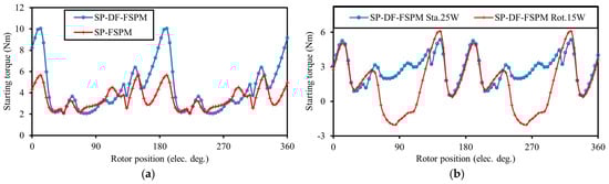
Figure 22.
Starting torque. (a) Healthy condition. (b) Faulty condition.
The variation in the average torque with the ratio of copper loss to the rated copper loss is illustrated in Figure 23, where the stator-to-rotor copper loss ratio is maintained at 1.667 in the SP-DF-FSPM machine, and Table 2 contains the corresponding rated currents for the SP-DF-FSPM and SP-FSPM machines. The torque density of the SP-DF-FSPM machine is constantly much higher than that of the SP-FSPM machine throughout the analyzed range. Additionally, the SP-DF-FSPM has a higher overload capability and is less likely to become saturated, as evidenced by the fact that the ratio of average torque generated by the SP-DF-FSPM and SP-FSPM machines increases with phase current.
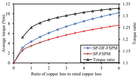
Figure 23.
Variation in average torque with copper loss of the SP-FSPM and SP-DF-FSPM machines.
4.5. Efficiency and Power Factor
As illustrated in Table 5, the loss distribution of the SP-DF-FSPM machine shifts compared to the SP-FSPM configuration, characterized by reduced stator core losses but increased rotor core losses. This redistribution stems from the SP-DF-FSPM’s rotor armature reaction, which increases magnetic saturation in the rotor core, while its reduced stator armature reaction slightly reduces stator iron saturation. Consequently, the SP-DF-FSPM machine exhibits higher total core losses; however, these remain secondary to copper losses, with stator losses constituting the dominant share at 59% of the total.
Table 5.
Efficiency and power factor comparison.
Despite this, the SP-DF-FSPM machine demonstrates superior overall efficiency, a benefit derived from its enhanced torque density. Furthermore, the stator component achieves higher power factors than that of the SP-FSPM machine, as calculated from the phase difference between the finite-element-predicted voltage and the phase current. The JMAG 23.0 software is employed to conduct 2D time-stepping transient finite element analysis coupled with an external circuit to evaluate the power factor. The machine is excited with rated current, and steady-state phase voltage and current waveforms are extracted. The power factor is then calculated based on the phase angle between the fundamental components of phase current and phase voltage, which are obtained through FFT processing.
5. Experimental Validation
Experimental validation of the preceding FEA results was conducted on an SP-DF-FSPM prototype, constructed in accordance with the optimized parameter set in Table 2. As illustrated in Figure 24, the machine features armature windings on both the stator and rotor elements. To enable external access to the rotor circuit, a slip ring is mounted directly onto the rotating shaft.
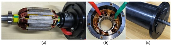
Figure 24.
Prototype of SP-DF-FSPM. (a) Rotor with slip rings. (b) Stator. (c) Assembled machine.
Static torque characteristics are evaluated by adopting the cogging torque measurement technique elaborated in []. Figure 25 presents a cogging torque comparison between the measured waveform and the corresponding FEA predictions. The experimental results confirm the simulated results. However, the measured peak torque values are marginally lower than those predicted. This divergence is primarily a consequence of mechanical and assembly tolerances inherent in the prototype.
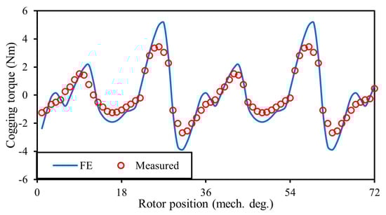
Figure 25.
Comparison of cogging torque.
The static torque waveforms under DC excitation of either the stator or rotor armature windings are presented in Figure 26a,b, respectively. The phase current values are set as rated current at time zero. While the measured torque waveforms exhibit some non-sinusoidal characteristics, primarily due to cogging torque, a favorable correlation between the predicted and experimental results is evident. Figure 27 displays the static torque characteristics when both stator and rotor windings are DC-excited. The total torque includes a component produced by the interaction between the stator and rotor magnetic fields. To account for the periodic nature of this interaction, additional experimental data were collected with the rotor position shifted by 72 mechanical degrees. The measured results show general consistency with the finite-element predictions, thereby validating the modeling approach and the design.
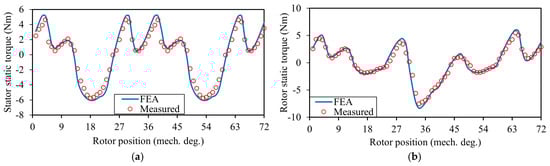
Figure 26.
Comparison of measured and FEA-predicted static torque. (a) Only stator current excitation. (b) Only rotor current excitation.
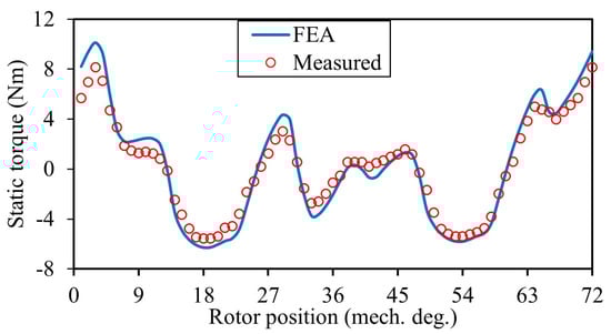
Figure 27.
Dual-excitation static torque.
6. Conclusions
This paper presents the development and investigation of an SP-DF-FSPM featuring armature windings on both the stator and rotor teeth to boost torque and enable fault-tolerant operation. A parameter sensitivity analysis is carried out on the SP-DF-FSPM and SP-FSPM machines, and they are optimized to achieve the maximum torque while maintaining self-start capability. While the optimal split ratio, stator tooth arc ratio, and rotor yoke thickness ratio vary significantly between the two topologies, parameters such as stator yoke thickness, magnet arc ratio, and rotor tooth arc ratio remain largely consistent.
A detailed comparative analysis of the electromagnetic performance indicates that the optimized SP-DF-FSPM achieves a 24.75% higher torque than its conventional counterpart when maintaining self-starting capability, while the dual-armature configuration enables 46.5% higher torque in the poly-phase FSPM machine. In addition, the SP-DF-FSPM machine achieves 24.57% higher torque per PM volume than the SP-FSPM, compared to a 39.6% increase for the poly-phase dual-armature FSPM over its counterpart.
Furthermore, under 40 W copper loss condition in healthy winding, the SP-DF-FSPM achieves 79.13% and 59.4% of the healthy torque when only stator and rotor winding is supplied, respectively, demonstrating superior fault-tolerance capability. These values correspond to 98.3% and 73.8% of the healthy torque of the conventional SP-FSPM machines, compared to 93.0% and 120.6% in poly-phase DF-FSPM machines. Under rotor-only fault-tolerant conditions, the self-starting capability is impaired and requires additional control strategies.
A prototype of the SP-DF-FSPM machine was manufactured and tested, effectively validating the analysis.
Author Contributions
Conceptualization, L.W.; Methodology, W.W. and H.Z.; Validation, U.T. and J.C.; Formal Analysis, L.W., U.T., W.W. and H.Z.; Investigation, L.W., U.T. and W.W.; Resources, T.W.; Data Curation, U.T. and J.C.; Writing—Original Draft, U.T.; Writing—Review and Editing, L.W., W.W. and H.Z.; Visualization, U.T.; Supervision, L.W. and T.W.; Project Administration, L.W. and T.W.; Funding Acquisition, L.W. All authors have read and agreed to the published version of the manuscript.
Funding
This research was funded by the National Science Fund for Distinguished Young Scholars under Grant 52225703.
Data Availability Statement
The raw data supporting the conclusions of this article will be made available by the authors on request.
Acknowledgments
The authors have reviewed and edited the output and take full responsibility for the content of this publication.
Conflicts of Interest
The authors declare no conflicts of interest.
References
- Gerlando, A.D.; Perini, R. Model of the Commutation Phenomena in a Universal Motor. IEEE Trans. Energy Convers. 2006, 21, 27–33. [Google Scholar] [CrossRef]
- Cros, J.; Viarouge, P.; Chalifour, Y.; Figueroa, J. A New Structure of Universal Motor Using Soft Magnetic Composites. IEEE Trans. Ind. Appl. 2004, 40, 550–557. [Google Scholar] [CrossRef]
- Lu, K.; Jakobsen, U.; Rasmussen, P.O. Single-Phase Hybrid Switched Reluctance Motor for Low-Power Low-Cost Applications. IEEE Trans. Magn. 2011, 47, 3288–3291. [Google Scholar] [CrossRef]
- Chen, H.; EL-Refaie, A.M.; Demerdash, N.A.O. Flux-Switching Permanent Magnet Machines: A Review of Opportunities and Challenges—Part I: Fundamentals and Topologies. IEEE Trans. Energy Convers. 2020, 35, 684–698. [Google Scholar] [CrossRef]
- Wu, L.; Ming, G.; Zhang, L.; Fang, Y.; Li, T.; Zheng, W. Comparative Study Between Doubly Salient PM Machine with New Stator/Rotor-Pole Number Combination and Biased Flux PM Machine. IEEE Trans. Ind. Appl. 2021, 57, 2354–2365. [Google Scholar] [CrossRef]
- Bai, J.; Liu, B.; Qiao, G.; Liu, G.; Liu, Y.; Zheng, P. Design and Analysis of a Novel Tubular High-PM-Utilization Transverse-Flux Linear Machine. IEEE Trans. Magn. 2022, 58, 8202505. [Google Scholar] [CrossRef]
- Bangura, J.F. Design of High-Power Density and Relatively High-Efficiency Flux-Switching Motor. IEEE Trans. Energy Convers. 2006, 21, 416–425. [Google Scholar] [CrossRef]
- Thomas, A.S.; Zhu, Z.Q.; Jewell, G.W. Comparison of Flux Switching and Surface Mounted Permanent Magnet Generators for High-Speed Applications. IET Electr. Syst. Transp. 2011, 1, 111–116. [Google Scholar] [CrossRef]
- Fasolo, A.; Alberti, L.; Bianchi, N. Performance Comparison Between Switching-Flux and IPM Machines with Rare-Earth and Ferrite PMs. IEEE Trans. Ind. Appl. 2014, 50, 3708–3716. [Google Scholar] [CrossRef]
- Evans, D.J.; Zhu, Z.Q. Novel Partitioned Stator Switched Flux Permanent Magnet Machines. IEEE Trans. Magn. 2015, 51, 8100114. [Google Scholar] [CrossRef]
- Wu, Z.Z.; Zhu, Z.Q. Analysis of Magnetic Gearing Effect in Partitioned Stator Switched Flux PM Machines. IEEE Trans. Energy Convers. 2016, 31, 1239–1249. [Google Scholar] [CrossRef]
- Awah, C.C.; Zhu, Z.Q.; Wu, Z.Z.; Zhan, H.L.; Shi, J.T.; Wu, D.; Ge, X. Comparison of Partitioned Stator Switched Flux Permanent Magnet Machines Having Single- or Double-Layer Windings. IEEE Trans. Magn. 2016, 52, 9500310. [Google Scholar] [CrossRef]
- Thomas, A.S.; Zhu, Z.Q.; Owen, R.L.; Jewell, G.W.; Howe, D. Multiphase Flux-Switching Permanent-Magnet Brushless Machine for Aerospace Application. IEEE Trans. Ind. Appl. 2009, 45, 1971–1981. [Google Scholar] [CrossRef]
- Raminosoa, T.; Gerada, C.; Galea, M. Design Considerations for a Fault-Tolerant Flux-Switching Permanent-Magnet Machine. IEEE Trans. Ind. Electron. 2011, 58, 2818–2825. [Google Scholar] [CrossRef]
- Li, G.J.; Ojeda, J.; Hoang, E.; Gabsi, M. Thermal-Electromagnetic Analysis of a Fault-Tolerant Dual-Star Flux-Switching Permanent Magnet Motor for Critical Applications. IET Electr. Power Appl. 2011, 5, 503–513. [Google Scholar] [CrossRef]
- Aboelhassan, M.O.E.; Raminosoa, T.; Goodman, A.; De Lillo, L.; Gerada, C. Performance Evaluation of a Vector-Control Fault-Tolerant Flux-Switching Motor Drive. IEEE Trans. Ind. Electron. 2013, 60, 2997–3006. [Google Scholar] [CrossRef]
- Taras, P.; Li, G.-J.; Zhu, Z.Q. Comparative Study of Fault-Tolerant Switched-Flux Permanent-Magnet Machines. IEEE Trans. Ind. Electron. 2017, 64, 1939–1948. [Google Scholar] [CrossRef]
- Wu, L.; Zhu, J.; Fang, Y. A Novel Doubly-Fed Flux-Switching Permanent Magnet Machine with Armature Windings Wound on Both Stator Poles and Rotor Teeth. IEEE Trans. Ind. Electron. 2020, 67, 10223–10232. [Google Scholar] [CrossRef]
- Wu, L.; Zheng, Y.; Fang, Y.; Huang, X. Novel Fault-Tolerant Doubly Fed Flux Reversal Machine with Armature Windings Wound on Both Stator and Rotor Teeth. IEEE Trans. Ind. Electron. 2021, 68, 4780–4789. [Google Scholar] [CrossRef]
- Ming, G.; Wu, L.; Yuan, J.; Ma, S.; Yang, J. Design and Electromagnetic Performance Analysis of Novel Dual-Armature Π-Core Doubly Salient Permanent Magnet Machines. IEEE Trans. Ind. Appl. 2024, 60, 498–506. [Google Scholar] [CrossRef]
- Chen, Y.; Chen, S.; Zhu, Z.Q.; Howe, D.; Ye, Y.Y. Starting Torque of Single-Phase Flux-Switching Permanent Magnet Motors. IEEE Trans. Magn. 2006, 42, 3416–3418. [Google Scholar] [CrossRef]
- Wang, D.; Feng, W.; Wang, B.; Xu, G.; Wang, X. Design, Prototype and Experimental Verification of Single Phase Flux Switching Motor Using Low Cost Magnets. IEEE Trans. Energy Convers. 2023, 38, 284–295. [Google Scholar] [CrossRef]
- Wang, D.; Xu, G.; Wang, B.; Wang, X.; Li, Z.; Wang, X. A New Hybrid Excitation Flux Switching Motor Using Low Cost Ferrites with Flux Regulation Capability. IEEE Trans. Energy Convers. 2025, 40, 382–393. [Google Scholar] [CrossRef]
- Zhu, Z.Q. A Simple Method for Measuring Cogging Torque in Permanent Magnet Machines. In Proceedings of the 2009 IEEE Power & Energy Society General Meeting, Calgary, AB, Canada, 26–30 July 2009; pp. 1–4. [Google Scholar]
Disclaimer/Publisher’s Note: The statements, opinions and data contained in all publications are solely those of the individual author(s) and contributor(s) and not of MDPI and/or the editor(s). MDPI and/or the editor(s) disclaim responsibility for any injury to people or property resulting from any ideas, methods, instructions or products referred to in the content. |
© 2025 by the authors. Licensee MDPI, Basel, Switzerland. This article is an open access article distributed under the terms and conditions of the Creative Commons Attribution (CC BY) license (https://creativecommons.org/licenses/by/4.0/).