Abstract
Glass–glass photovoltaic (PV) technologies for building-integrated PV (BIPV) applications are increasingly used in construction, for many positive aspects. These multi-functional systems are rather complex to characterize and need the technical knowledge of many experts due to the combination of electrical, mechanical, and architectural needs. Structurally speaking, glass–glass BIPVs are in fact required to withstand possible superimposed thermal and mechanical loads under normal operational conditions, as well as in accidental scenarios. As such, the impact of their geometrical features and mechanical details on their overall performance is a key issue in safety assessments. Glass cracking, for example, represents a critical condition, but additional important phenomena can take place before fracture. In this paper, attention is paid to the elaboration of thermal and mechanical considerations for glass–glass BIPVs under increasing temperatures. For comparative purposes, a 400 × 400 mm tempered prototype is investigated. Based on a robust Finite Element (FE) numerical approach, the present study investigates some important thermo-mechanical mechanisms of the first heating stage (i.e., ≈150–250 s of exposure, for the examined configurations), before glass cracks. It is shown that—even in the elastic stage before glass cracking—important modifications of temperature-dependent materials can reduce the load-bearing capacity of the examined BIPV systems. Also, variations in cross-sectional composition (i.e., thickness of glass covers) and/or in the mechanical restraints (4L, 2L, and 4P, in the following) can have significant, critical impacts on the reference performance indicators, such as the global bending stiffness, the stress evolution and peaks in the BIPV components, and the deflection.
1. Introduction
Glass–glass photovoltaic (PV) modules are modern technological solutions that are increasingly used in construction [1,2]. In building-integrated (BIPV) applications, PV collectors have two primary roles, given that they have a combined electrical and structural function in the building envelope, replacing traditional components. Examples can be found in their application in windows, balustrades, and façades (see [3] and Figure 1), as well as in skylights and even pedestrian systems.
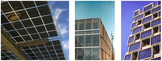
Figure 1.
Examples of BIPV applications (figures reproduced with permission from @Unsplash).
The typical features of glass–glass BIPVs are represented by the use of a two-ply laminated glass section. Compared to traditional structural glass applications, however, there are some important variations that should be taken into account. For classical load-bearing glass components, the glass panels of a two-ply laminated section have a thickness that generally spans from 8 mm to 12 mm for each layer (depending on the specific structural design requirements), and they are bonded by an interlayer (0.76 mm or 1.52 mm in thickness) that allows them to mechanically interact [4]. The materials used for the interlayer include PVB, SG, and EVA solutions.
In BIPVs, the solar cells and the electrical components are directly embedded in the two-ply glass section. Also, relatively thin glass layers (≈3–5 mm thickness each) are often used to compose the BIPV cross-section. According to several studies in the literature, the reason for using a specific detailing for glass–glass BIPV cross-sections is the optimal electrical functionality and efficiency [5,6]. Their combination with other parameters, such as different mechanical restraints (i.e., linear or discrete fixings), size features, and superimposed loads, should be properly assessed.
Generally speaking, depending on their use, glass–glass BIPVs are in fact required to accommodate and satisfy specific building demands (i.e., structural and mechanical performance indicators that are typical of building architectural components like façades, roofs, balustrades, etc. [3,4]). Careful attention is thus required for the analysis and assessment of BIPVs, in terms of their load-bearing capacity, bending stiffness, resistance to impact, and even fire safety [3,4]. The thin glass covers are in fact rather vulnerable components, and appropriate methods of analysis are needed to determine their performance during both ordinary design processes and accidental load application [3]. Among other examples, elevated temperatures and fire accidents induce critical conditions for the load-bearing BIPV components [7,8,9], and their safety assessment involves in-depth investigations, often based on full-scale experiments [10,11,12,13].
In this paper, we focus on the numerical analysis of BIPVs under elevated temperature scenarios, such as fire. The goal is to provide some insights to assess and emphasize possible critical mechanisms that could take place in the initial heating stage for these sandwich sections, rather than on the study of their full disruptive response up to collapse.
The used strategy is adapted from the existing design and structural performance assessment approaches for two-ply glass sections under mechanical loads. The limit condition, in this case, is in fact associated with the detection of the first crack initiation in the glass covers, which represents a major event and a transition between the elastic and the post-cracked stages. The stress analysis of two-ply glass covers in fire is still key but not a sufficient step for performance assessment. Accordingly, the present study numerically investigates the most important phenomena that can be expected in BIPVs under increasing temperatures, up to the first crack detection in glass.
Overall, the study fits with the urgent international need to assess the structural performance and safety of BIPVs subjected to unfavorable operational conditions [14,15]. Certainly, a more exhaustive analysis should also investigate the post-fracture stage of BIPVs in fire, up to collapse. However, even more uncertain and complex phenomena take place after fracture. Moreover, some important findings can be revealed from first crack detection, to support future investigations.
In particular, major results from a Finite Element (FE) numerical analysis carried out in ABAQUS [16] on small-scale glass–glass BIPV samples under uniformly distributed, time-varying elevated temperatures are critically discussed in this paper, to verify their local and global structural performance. As shown, the progressive temperature increase in the BIPV components is associated with a material modification that—in terms of mechanical considerations—leads to the relaxation and redistribution of the expected tensile stress peaks in the BIPV layers. These phenomena have been largely studied for other structural glass applications for buildings, such as panels and beams under sustained mechanical loads and fire [17,18,19,20], but limited literature efforts are available for PV or BIPV systems in fire. The study in [21], for example, is dedicated to single-glass PV specimens under elevated temperatures, while glass–glass BIPVs in fire are numerically investigated in [22], with the support of experiments from the literature. As such, the present contribution tries to support the technical knowledge spread for this complex and wide topic.
To this end, Section 2 briefly recalls the literature studies that numerically investigated the thermo-mechanical response (not in fire) of PV solutions. The presently adopted modelling strategy is described in Section 3, and validated in Section 4, where the selected performance indicators are also discussed. Major numerical results are presented in Section 5, where sensitivity to some selected features (such as the glass type and thickness, or the mechanical restraints) are discussed as a function of the exposure time.
2. Modelling the Thermo-Mechanical Response of PV Systems Under Elevated Temperatures: Existing Studies
PV systems are characterized by a thin and rather flexible cross-section, which is combined with the typically high vulnerability of the constituent materials (glass, solar cells, encapsulant) to severe mechanical loads and high temperatures. Consequently, it is important to quantify and verify the mechanical effects of moderate–high temperatures and recognize in advance possible critical conditions. Increasing temperatures are in fact associated with some important thermo-physical phenomena and modifications in materials, and thus with a reduction in the expected load-bearing capacity of these sandwich systems.
Over the years, the effects of varying temperatures on single-glass PV components have been explored by many research studies, based on different numerical strategies and approaches. For example, it was shown in [23] that the use of FE computations represents an efficient support for possible design optimization and certification. Also, FE tools can be used to extend the typical testing configurations that are recommended by standards.
Many literature studies, however, have focused especially on the electrical side, for the analysis of thermal effects for PV systems under ordinary operational conditions. Siddiqui et al. [24] formulated a very complex model to account for the performance of PV modules under variable operational conditions, with different inclinations and wind parameters. Studies carried out by Özkalay et al. [25] experimentally verified that operational temperatures in BIPV components can rise up to 100 °C in the Switzerland region (and even more in different regions [26]).
Local and global thermal analyses for PVs can be found in [27,28,29,30,31], along with many others. For fire safety accidents, it is clear that appropriate countermeasures should be generally taken into account. However, the numerical assessment of BIPVs in fire is rather challenging, due to the combination of multi-performance requirements and load-bearing building demands [32]. For example, challenges include the following:
- Glass material can suffer thermal shock, which depends on multiple geometrical and thermo-physical aspects, and thus requires robust calculation methods [33,34,35];
- The commercial products in use for the encapsulant (PVB or EVA) are sensitive to thermal variations, in the form of a progressive relaxation and viscoelastic response, which involves a decrease in the shear rigidity of the bonding layer, and thus affects the bending stiffness of the BIPV sandwich section [36,37,38];
- The global bending capacity of a BIPV system is strongly affected (similarly to ordinary operational conditions) by the features of the mechanical boundaries, which may include linear restraints but also discrete mechanical point-fixings, with totally different structural performances [39,40,41];
- Overall, it is clear that the exposure of BIPV systems to elevated temperatures is associated with primary issues that derive from the features of the constituent materials but also depend on the reciprocal interaction of BIPV components, as well as some possible unfavorable geometrical aspects that should be properly addressed.
3. Present Numerical Modelling Strategy
3.1. Setup, Parameters, and Goal
To explore the thermo-mechanical performance of a selection of glass–glass BIPVs subjected to increasing temperatures, this paper is focused on the analysis of thermal and mechanical effects in the first heating stage (i.e., before glass fracture), which is of utmost importance to assess the load-bearing response of the BIPVs [19,20].
In a relatively short time interval (less than 250 s, for the presently examined configurations), the out-of-plane bending stiffness of the BIPV module can be severely reduced by the progressive temperature spread. This means that even rather limited mechanical loads (superimposed to the thermal exposure) could result in major consequences. Such a consideration requires special attention for fire safety and structural safety assessments and is of interest for many practical applications in buildings.
Among other examples of technical interest, the setup schematized in Figure 2 is taken into account in this paper, which corresponds to a glass–glass BIPV module in a vertical layout subjected to increasing temperature on one side only. In addition to the thermal exposure, the BIPV components are subjected to the mechanical load deriving from their self-weight G. Such a vertical layout is typical of façade components and balustrades, where the BIPV modules are used with linear or discrete mechanical fixings. At this stage, the effect of possible tilt angles or even additional superimposed mechanical loads (i.e., wind pressure) are disregarded.
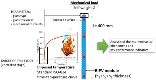
Figure 2.
Reference setup for the parametric numerical analysis (side view).
Taking inspiration from earlier studies (see for example [21,22]), a bi-facial, glass–glass small-scale PV sample was analyzed. The edge size of the module was set in L = 400 mm × 400 mm, while the cross-section was composed of two layers of glass (h1 = 3.2 mm + h2 = 3.2 mm thick), bonded by a PVB encapsulant (he = 1.52 mm its thickness). The encapsulant was used to embed hc = 0.2 mm thick, 156.75 mm × 156.75 mm bi-facial solar cells (PERC 5BB type). The model components for the reference configuration are schematized in Figure 3. Regarding the mechanical restraints, a rigid continuous metal frame was initially used to linearly fix all the edges of the glass covers (Figure 3). Finally, in terms of thermal exposure, a conventional, uniformly distributed, time-varying temperature function was used on the exposed glass surface; see Figure 2 [42].
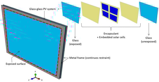
Figure 3.
Assembly of the typical numerical model (ABAQUS) for the glass–glass BIPV module with four linearly restrained edges (4L configuration).
Through the numerical investigation, a multi-step thermo-mechanical analysis was carried out for each examined configuration, by highlighting a combination of features. According to Table 1, the study was carried out by considering possible variations in the following:

Table 1.
List of examined features for the present investigation. * Reference BIPV configuration for the numerical study.
- (i)
- Thickness of the glass covers.
- (ii)
- Glass type (AN: annealed; HS: heat-strengthened; FT: fully tempered).
- (iii)
- Features of the mechanical restraints (with four (4L) or two (2L) linearly restrained edges, or four-point fixings (4P), see Figure 4). In this last case, it is important to recall that an ideally rigid bond was used at the interface between the glass covers and the metal components.
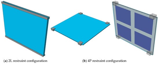 Figure 4. Example of numerical models for the analysis of glass–glass BIPV systems under different mechanical boundaries: (a) two linearly restrained edges (2L configuration) or (b) four-point fixings (4P configuration) (ABAQUS).
In this regard, it is important to note that the performance of AN and HS glass solutions was taken into account (for the 4L configuration) in a preliminary stage of the study, to emphasize the different responses of several glass types to the imposed thermal scenario. The majority of the simulations were subsequently carried out for the tempered glass samples only (FT). In parallel, the reference FE model of Figure 3 was adapted to reproduce different boundary details and exposed/unexposed surfaces (Table 1).
3.2. Solving Approach
The numerical study was based on a combination of different types of analyses that were carried out for each selected configuration of Table 1, namely the following:
- Thermal, transient “heat transfer” analysis for the BIPV system subjected to the uniformly distributed, time-varying temperature function on the exposed surface of glass (i.e., Figure 2);
- Static simulation (with input nodal temperatures varying over time, based on step 1);
- Frequency analysis (carried out on the BIPV system subjected to predefined thermal scenarios, based on the nodal temperature input from step 1).
A major support was taken from past experiences on BIPV modelling and characterization [21,22], as well as from thermo-mechanical analyses on glass laminates subjected to elevated temperatures [17,18,19,20].
The presently adopted thermal interactions, in particular, are described in detail in [17,18,19,20,21,22]. For the heat transfer analysis (step 1), thermal interactions were in fact considered on the front and back covers of the BIPVs, while adiabatic boundaries were used at the edges. For the exposed surface of the front glass cover and for the unexposed glass one, the convective heat transfer coefficient was separately calculated based on [43,44].
The standard ISO time-varying temperature curve schematized in Figure 2 was reproduced to introduce the thermal load on the front glass cover. This assumption was supported by the so-defined “surface radiation” and “surface film condition” features of ABAQUS library [17,18,19,20,21,22]. Unlike past studies, the attention of simulations was specifically focused on the first ≈150–250 s of exposure (i.e., pre-cracked stage).
In terms of mechanical analysis of the explored BIPVs (step 2 and step 3), the out-of-plane bending response and sensitivity to increasing temperatures was studied in step 2 by importing the desired thermal distribution over time from step 1, for all the model nodes. Similarly, the frequency analysis in step 3 was performed for a selection of imported thermo-mechanical configurations (i.e., BIPV composition, type of mechanical restraint, exposure time), in order to predict the fundamental vibration frequency and shape of each BIPV module, whilst taking into account the effects of increasing temperatures.
3.3. Elements, Boundaries, and Constraints
Depending on the type of analysis (i.e., thermal or mechanical), each constituent layer and BIPV component was numerically reproduced in ABAQUS by means of eight-node heat transfer (DC3D8) and linear brick (C3D8R) elements, respectively, as an independent part. The reference FE assembly included the glass covers, the encapsulant layer, the embedded solar cells, and the metal restraints (i.e., Figure 3 and Figure 4). All the adjacent layers were ideally bonded by surface-to-surface rigid “tie” constraints. Further electrical components were disregarded, and their possible critical role in contributing to the temperature spread should be separately investigated. A refined mesh pattern was taken into account. According to preliminary sensitivity considerations, the resulting pattern included four elements in the thickness of each glass layer and eight elements in the thickness of the encapsulant/cells (Figure 5). The final model consisted of ≈105,000 elements and ≈138,000 DOFs.
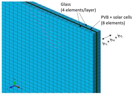
Figure 5.
Detail of the adopted mesh pattern for the reference glass–glass BIPV module (ABAQUS).
3.4. Material Properties
The input properties for all the relevant materials (glass, PVB for the encapsulant, solar cells, and aluminum for metal restraints) were obtained from the literature (Figure 6). A key role in the present simulations was assigned to the temperature-dependency of material properties.
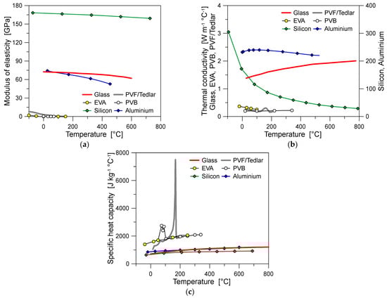
Figure 6.
Input material properties for the numerical analysis: (a) modulus of elasticity; (b) thermal conductivity; (c) specific heat.
Glass was described as in [22], in the form of a temperature-dependent, linear elastic material. This means that the possible material degradation and state modification with the increasing temperature was numerically reproduced by a reduction in the modulus of elasticity, see Figure 6a. For the purpose of the present investigation (i.e., first stage of thermal exposure, until glass failure) any other failure mechanism for glass was disregarded. Accordingly, the analysis of stress evolution and peak values in the glass covers was continuously monitored (at each time instance of the analysis), to avoid unrealistic numerical predictions for AN, HS, or FT glass types.
Regarding the PVB encapsulant (temperature-dependent, linear elastic law), the input parameters were assumed from [17]. It should be noted that—for comparative purposes only—the EVA properties are also shown in Figure 6, where the modulus of elasticity was derived from [45], while the thermal conductivity was estimated based on [46].
In the description of the solar cells (temperature-dependent, elastic–plastic law), input from the literature was taken into account, using the studies [47,48]. In particular, the mechanical characterization of solar cells was initially based on [49,50,51], in terms of modulus of elasticity and failure stress. Following the four-point bending experiments and simulations based on the beam theory reported in [50], the modulus of elasticity was set to Esil = 166 GPa for the solar cells at room temperature. Its reduction with higher temperatures was considered based on the experimental trend reported in [49]. The corresponding failure stress was initially set as σu,sil = 106 MPa, to account for the possible cracking of cells in bending [50,51]. The so-calibrated parameters were also assessed based on original experiments (see Section 4.3). Finally, for the supporting metal components, a temperature-dependent elastic–plastic constitutive model was considered to describe the aluminum components, with input properties derived from [52,53].
4. Strategy for the Thermo-Mechanical Numerical Study
4.1. Preliminary Numerical Validation
The preliminary validation step was focused on the thermal analysis in normal operational conditions and was carried out on a full-size commercial single-glass PV module with a PET backsheet [41]. The PV specimen consisted of a 1.15 m × 1.75 m module, with single-glass section (h1 = 3.2 mm thick, FT cover) and a continuous aluminum frame. The EVA encapsulant (he = 1 mm in thickness) was used to embed 0.2 mm thick monocrystalline solar cells (18 × 6 = 108 in total), with 1 mm thick PVF/Tedlar backsheet (Figure 7a).
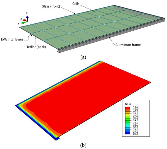
Figure 7.
Nodal temperature distribution (NT11) of a single-glass PV module in normal conditions, for modelling validation (ABAQUS): (a) assembly [41] and (b) temperature (legend values in °C).
The thermal heat transfer analysis was carried out with T = 20 °C and G = 800 W/m2. The expected temperature in the cells was 42 °C. From the present modelling strategy, a temperature distribution like in Figure 7b was numerically obtained. The maximum temperature in the solar cells was predicted to be 43.93 °C (4.5% scatter), which correlates strongly with many examples from the literature (3–5% the average temperature scatter).
To further verify the validity of modelling assumptions for BIPVs subjected to elevated temperatures, the present strategy was implemented in accordance with [21,22]. Figure 8a, in particular, shows the temperature evolution in the front and back glass covers of the small-scale single-glass PV specimen investigated in [21]. In Figure 8b, the temperature evolution in the front glass cover and in the metal frame are reported for the full-scale glass–glass BIPV specimen presented in [22], which was tested in a conventional furnace setup. Even considering the background complexity and uncertainty of similar simulations, in both cases it is possible to see a rather close agreement between the numerical and the experimental estimates, which suggests a certain robustness for the model calibration.
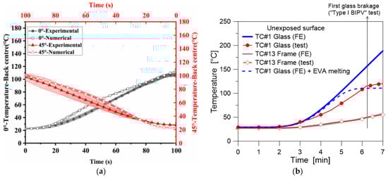
Figure 8.
Temperature evolution for BIPV components under elevated temperatures and fire, for modelling validation (ABAQUS): (a) single-glass PV sample (figure reproduced from [21] under the terms and conditions of a CC-BY license agreement) and (b) glass–glass BIPV sample in a furnace setup (figure reproduced from [22] under the terms and conditions of a CC-BY licence agreement).
4.2. Selected Performance Indicators
The analysis of numerical results was carried out by focusing the attention—in the pre-cracked stage—on some key performance indicators of primary interest for the assessment of the mechanical performance of BIPVs, namely the following:
- The initial geometrical imperfection (i.e., shape and amplitude) of each BIPV module, due to the imposed thermal scenarios;
- The analysis of the evolution over time of the temperature peak and gradient on the exposed glass cover;
- The evolution of the tensile stress peaks in the exposed glass cover, as a function of the thermal exposure;
- The trend over time of the out-of-plane deflection at the center of each BIPV module, and the corresponding reaction forces at the mechanical restraints;
- The amplitude of the stress and strain peaks in the solar cells;
- The fundamental vibration frequency of the BIPV system when exposed to different thermal configurations.
4.3. Failure Detection Under Elevated Temperatures
The first step of the procedure was represented by the detection of the limit condition corresponding to first crack initiation in the glass covers, which was verified according to some consolidated parameters and approaches from the literature. The thermal failure detection of glass due to progressive heating, in particular, was based on [54,55], such as the following:
- “Temperature approach”: the measured thermal gradient between the exposed and coldest regions of the glass cover subjected to progressive heating was compared to the reference limit values reported in Table 2;
Table 2. Allowable thermal gradients (ΔTallowable) for glass and corresponding stresses (σt,allowable).
- “Stress approach”: the resulting stress peaks in tension in the exposed glass cover (due to thermal and possible superimposed mechanical effects) were monitored during each analysis and compared with the nominal allowable thermal stress values reported in Table 2.
When considering the results presented in Table 2—which refers to the thermal failure of different glass types—it is important to recall that the characteristic tensile strength of FT glass under mechanical loads (at room temperature) is equal to 120 MPa. Even lower values can be expected at the edges or near the holes [55]. The present study includes, however, both thermal and mechanical loads in the glass covers. As such, the more conservative value from Table 2 (116.20 MPa) was preliminarily taken into account for the “stress approach” and compared with the simulated stress peaks in glass. This assumption suggests that the superimposed mechanical loads (i.e., self-weight, wind, etc.) should be verified with careful consideration, as they could be particularly critical for some configurations (i.e., different mechanical restraints, aspect ratio, etc.) that are not considered in the present study.
In addition to glass covers, the attention was also focused on the stress and strain evolution in the solar cells. In this latter case, due to the lack of more specific experimental data for failure detection under thermal exposure, the ultimate stress value was initially derived from experiments from the literature (i.e., σu,sil = 106 MPa, as specified in Section 3.4).
For further confirmation of literature failure parameters, a set of original three-point bending experiments were indeed carried out in laboratory conditions, on small-scale samples of solar cells. These samples were obtained by cutting some strips from PERC 5BB solar cells (156.75 × 156.75 mm their original size), and each strip measured 30 mm in width.
In the adopted three-point bending setup, the distance of supports was set at 60 mm, while a quasi-static, monotonic vertical load was imposed at the mid-span section of each specimen (with 2 mm/min the strain rate) and gradually increased until failure (Figure 9a). At room temperature, the stress–strain response of these samples was found to agree with Figure 9b. In further detail, the average failure stress was calculated as σu,sil = 118.38 MPa (±6.63 MPa), which agrees rather well with data from the literature (Section 3.4). The corresponding failure strain was quantified as 0.1186% (±0.0065%). In general, a sudden brittle failure mechanism was observed for all the tested strips, as can be seen in Figure 9b from the abrupt drop in the reported stress–strain curves. The so-calculated average failure strain was thus taken into account for the present investigation (Section 5).
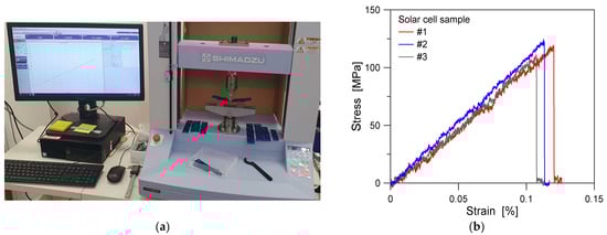
Figure 9.
Three-point bending experiments on solar cell samples at room temperature: (a) test setup and (b) typical stress–strain results.
5. Numerical Results
5.1. Temperature Evolution
Attention was first given to the distribution and evolution of temperatures in the BIPV components, given that they represent a first useful tool to predict any possible thermal shock and first breakage of glass (i.e., Table 2), but they also possibly affect the mechanical and thermo-physical properties of the constituent materials (i.e., Figure 6).
To this end, a set of control points was considered, as in Figure 10 (where the example shows the 3.2 + 3.2 mm BIPV module with four edges restrained—4L).
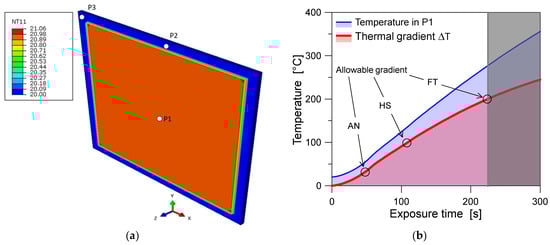
Figure 10.
Thermal analysis (4L configuration): (a) example of temperature distribution at the beginning of thermal exposure (nodal temperature N11 in °C) and (b) temperature trend over time, as measured at the center of the exposed glass cover and in terms of thermal gradient ΔT (ABAQUS).
Following Table 2 and Figure 10, the thermal shock is expected in about ≈220 s of exposure for the BIPV system composed of FT glass panes, ≈110 s for HT glass layers, and ≈55 s in the case of AN glass. This simplified approach for failure detection in the glass covers—whilst approximate—can offer useful preliminary estimates about the initiation of the expected fracture mechanisms [55]. The same conventional approach was in fact used in [22] for a full-scale BIPV sample under fire (with 6 + 6 mm FT glass covers bonded by 1 mm thick EVA encapsulant, 1.046 m × 1.719 m in size (width × height), and with a 4L restraint configuration). In that case, the numerically estimated crack initiation in the exposed glass cover was found to have a less than 30 s scatter (in terms of exposure time) compared to the full-scale experiment. The temperature evolution with the exposure time was also well-simulated (Figure 8b). As reported in Table 3, however, the size and aspect ratio (i.e., squared or rectangular) of BIPV systems certainly represents additional influencing parameters that should be further explored.
Table 3.
Predicted failure time for the exposed glass cover, based on the more conservative condition based on Table 2 (i.e., thermal gradient (ΔT)), for BIPVs in the 4L restraint configuration.
In the present study (0.4 m × 0.4 m samples), such a relatively short time interval from Table 3—whilst associated with still elastic, pre-cracked glass covers—is characterized by some important variations in the key performance indicators of the BIPV section. For this reason, major attention was paid to the post-processing of parametric numerical results.
The presence of different mechanical boundaries and cross-section composition, for example, was found to have important effects in the thermal analysis of the examined BIPVs (Figure 11), and consequently on the associated mechanical parameters.
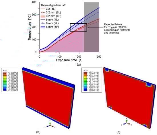
Figure 11.
Effect of mechanical restraints for thermal analysis: (a) predicted thermal gradient and (b,c) example of temperature distribution (nodal temperature N11 in °C) at the first stage of thermal exposure, for 2L and 4P configurations (ABAQUS).
Considering the BIPV system composed of FT glass layers, for example, it was numerically observed that an increase in the glass thickness (from 3.2 mm to 6 mm) can ideally give a +15% increase in the corresponding failure time (due to thermal gradient) for the reference 4L configuration. This outcome suggests that even when doubling the thickness of the glass in the BIPV cross-section, such an increase does not provide proportional mechanical benefits for the BIPV system as a whole.
Reducing the mechanical restraints (from 4L to 2L or 4P conditions, respectively) indeed reduces the expected failure time by about −8% and −10% compared to the 4L setup. This effect can be noted in the red curves proposed in Figure 11a. Minor effects were observed for the 6 + 6 mm section, compared to the 3.2 + 3.2 mm system. When modifying the mechanical boundaries, the temperature distribution was indeed partly affected in the region of the mechanical restraints (see Figure 11b,c). The predicted local temperature variations as in the point-fixed (4P) configuration of Figure 11c were found to have a huge impact on the possible initiation of fracture mechanisms in the glass, and to reduce the global redundancy of the BIPV system.
5.2. Thermal Exposure and Associated Mechanisms
The non-uniform temperature increase in the resisting section of a BIPV module is commonly associated with thermal expansion effects, and with thermal stress peaks that increase according to the temperature spread. This aspect is particularly relevant because these phenomena are superimposed to possible mechanical loads that the glass covers are required to accommodate. The numerical analysis showed that even rather moderate temperature peaks and gradients in the BIPV section can be associated with a large increase in the associated global imperfections, and corresponding bending stress peaks.
In this regard, Figure 12a shows the deformed shape at a given time instance of thermal exposure for the BIPV module with a 4L configuration. As shown, the reported out-of-plane displacements correspond to the fundamental deformed shape of a linearly supported plate, which induces initial bending stresses in the layers. However, this amplitude progressively increases with the temperature spread and is also combined with the thermal degradation of materials (Figure 6).
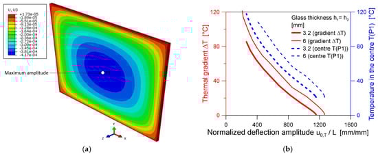
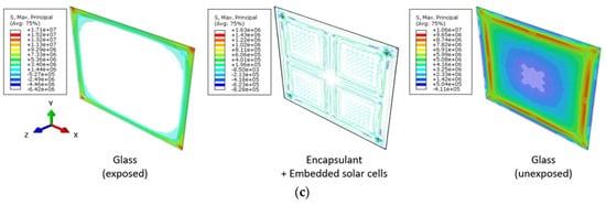
Figure 12.
Thermal effects (4L configuration): (a) example of initial expansion and global geometrical imperfection due to heating (out-of-plane displacement U3 in meters) and (b) maximum amplitude trend due to temperature effects, with (c) maximum principal stress distribution in each BIPV layer (legend in Pa), (ABAQUS).
To this end, a more detailed analysis of global deformation effects can be drawn by considering the maximum amplitude, u0,T, and its correlation with the observed temperature scenarios. Figure 12b shows the normalized imperfection amplitude measured in P1 (i.e., u0,T as a function of the BIPV size L), and its trend with two temperature parameters: the measured temperature gradient ΔT (on the left Y axis) and (on the right Y axis) the temperature peak in the center of the glass cover T(P1). It is possible to see a typical non-linear increase in the thermally induced imperfection, as a function of the corresponding thermal gradient/peak.
Considering that the rigidity of materials also decreases with the temperature increase (i.e., Figure 6), it is clear that this effect is not only associated with a bending stress increase in the glass covers (and in the other components), but also with a progressive transition of the tensile stress peaks (especially for the exposed glass layer) towards the coldest regions of the covers (i.e., the edges and the corners). This last phenomenon is summarized in Figure 12c, in terms of principal stress distribution in the exposed (front glass cover), intermediate (encapsulant and solar cells), and unexposed (back glass cover) BIPV layers.
Finally, possible modifications in the features and layout of the mechanical restraints can further modify the expected thermal effects. Amongst the selected configurations, the maximum effects were achieved for the 2L configuration, which was typically associated with a beam-like cylindrical deformed shape for the examined BIPV systems, as well as with more pronounced imperfection amplitudes. This last aspect is summarized in Figure 13, where the normalized imperfection amplitude is plotted as a function of the exposure time (Figure 13a) and the associated deformed shapes are qualitatively shown in Figure 13b for the 4L (on the left) and 2L (on the right) configurations, respectively. From Figure 13a, in particular, it can be seen that the normalized imperfection amplitude is typically very small after a few seconds of thermal exposure (i.e., ≈ L/1200 = 0.33 mm for the 6 + 6 mm system with 4L) but drastically increases with the exposure time (and thus with the temperature), up to ≈ L/1200 = 2 mm after 140 s. Different trends and imperfection amplitudes can be seen for the other configurations: the thinner the glass covers, the larger the imperfection amplitude. Moreover, the largest deformations are associated with the 2L configurations, compared to the 4L, due to the partial removal of mechanical restraints and the increased flexibility of the BIPV system.
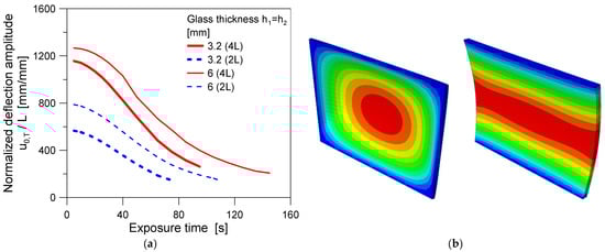
Figure 13.
Thermal effects on global imperfection: (a) normalized global imperfection amplitude as a function of the exposure time (4L and 2L configurations) and (b) corresponding (amplified) deformed shapes (ABAQUS).
In conclusion, another important effect was found in terms of the evolution of maximum stress and strain in the embedded solar cells, which may possibly affected by premature brittle failure, even when the glass panes are still intact. The weak shear bonding offered by the temperature-dependent encapsulant (i.e., Figure 6) is in fact associated with a rather flexible and “uncoupled” bending response of the BIPV section.
An example of strain distribution in the BIPV components is presented in Figure 14, after ≈70 s of thermal exposure, for the 6 + 6 mm system (2L configuration). The selected time instance corresponds to ≈60 °C of thermal gradient ΔT for the exposed glass cover, with a global beam-like geometrical imperfection, which was measured in up to ≈L/400 in the center of the glass. Whilst a relatively small stress amplitude was predicted for the encapsulant layer, the stress and strain peaks were measured in the solar cells, which are typically affected (and are required to accommodate) by the global bending deflection of the BIPV system.
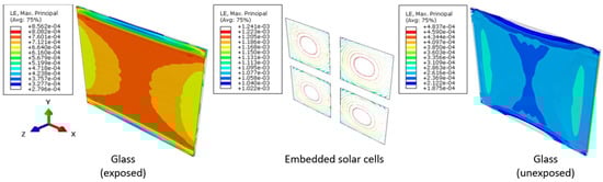
Figure 14.
Thermal effects (2L configuration): example of strain distribution (principal component of logarithmic strain LE) due to thermal exposure (ABAQUS).
As shown in Figure 14, the predicted strain amplitude was in fact higher in the solar cells than in the glass panes. This suggests that the stiffer the composite BIPV section, the higher the risk of premature brittle failure for the solar cells, even for glass covers that remain elastic and relatively small–medium thermal gradients. Moreover, in this case, different mechanical boundaries can further anticipate any premature failure mechanism. A more in-depth investigation on fracture mechanisms for solar cells would, however, require the use of debonding models (i.e., at the interface with the encapsulant layers), as well as the description of additional BIPV components (i.e., interconnects and electrical components) that are known to induce additional major local effects in similar systems.
Structurally speaking, the presented numerical results (shown in Figure 14) confirm in any case that the detailing of the mechanical restraints can induce important modifications in the global and even local response of BIPV systems.
5.3. Thermal Exposure and Global Bending Stiffness
For the global analysis of thermal exposure effects in terms of out-of-plane bending for the examined BIPV systems, we finally considered their vibration frequency f1, which was selected as a robust performance indicator to implicitly track the bending stiffness Deff.
The “effective” composite flexural stiffness of a typical BIPV section is in fact commonly affected by several basic geometric parameters and restraints, and by the mechanical features of the constituent layers [41]:
Moreover, from a theoretical point of view, the following is expected:
A key role for estimating Deff between the bound limits Dabs and Dfull, which denote, respectively, the bending stiffness of the BIPV section under weak/null shear bonding offered by the encapsulant (“abs”, layered limit) or with ideally rigid connection in shear (“full”, monolithic limit), can be found in the effect of elevated temperatures and fire exposure, given that progressive heating reduces the mechanical stiffness of the used materials (Figure 6).
Whilst the mechanical contribution of the solar cells can be disregarded for vibration frequency considerations, this is not the case for the other mechanical BIPV components. Also, the weakest bonding configuration can theoretically be associated with the bending stiffness contribution of the uncoupled front and back glass covers alone:
with i = 1, 2, and
where
and he is the encapsulant thickness.
The associated vibration frequency f1 of the BIPV module can consequently be estimated (depending on the features of mechanical restraints) based on classical analytical models in the literature. Assuming that the frame along the edges is ideally rigid, as in Figure 3, for example, the associated vibration frequency can be calculated as follows:
with and L = 400 mm as the BIPV dimensions, and (for a square shape, as in the present study). Practical considerations and parametric experimental/numerical studies in terms of vibration frequency for the commercial single-glass PV module of Figure 7 have been, for example, reported in [41], under normal operational conditions, to assess the consequences of the encapsulant degradation.
For the present study, according to Equation (8), once f1 is known and the geometrical parameters of the BIPV system are fixed, the corresponding Deff value can be directly extrapolated to obtain a quantitative estimate of its global out-of-plane bending stiffness. As such, any variation of f1 due to thermal exposure can be implicitly used to quantify the bending stiffness sensitivity to the temperature increase.
Compared to earlier evidence from the literature, the present numerical study includes the critical role of progressive heating, which is typical of many ordinary or accidental scenarios for BIPV systems. Typical numerical results can be found in Figure 15, where the fundamental frequency variation is calculated as follows:
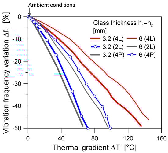
Figure 15.
Vibration frequency variation for the examined BIPV system (4L, 2L, and 4P configurations), as a function of the measured thermal gradient ΔT (ABAQUS).
The fundamental frequency variation is calculated at a given time instance of thermal exposure and is reported as a function of the corresponding thermal gradient ΔT. Also, f1,ΔT is the associated vibration frequency prediction and f1,amb is the vibration frequency of the same BIPV module, but at ambient temperature.
In further detail, Figure 15 highlights a rapid decrease in the fundamental frequency of the system, for moderate thermal gradients. As long as the temperature gradient increases, the frequency reduction increases further.
Such a phenomenon can be implicitly associated with the severe mechanical degradation of the constituent materials, particularly the encapsulant, due to the progressive non-uniform heating of the resisting cross-section. According to Figure 6, the reduction in the modulus of elasticity has an implicit role in these observations, especially considering that the encapsulant governs the coupled mechanical response of the glass covers. Whilst the examined range of temperatures in Figure 15 (and throughout the present investigation) has negligible effects on the modulus of elasticity of glass (see Figure 6), this is not the case of the encapsulant, and there are therefore consequences on the effective bending stiffness Deff.
Also, it is important to recall that the thermal stress peaks corresponding to the thermal gradients of Figure 15 are still associated with a fully linear elastic response for the front and back glass covers of the BIPV system, which is considered to be composed of FT glass (Table 2). Accordingly, the stress analysis in the glass would result in a positive/elastic outcome, whilst it is clear from Figure 15 that the mechanical performances of the BIPV systems still require important modifications.
A more detailed analysis of Figure 15 shows that, apparently, the 6 + 6 mm system is less affected than the 3.2 + 3.2 mm system by elevated temperatures. However, it still highlights a frequency decrease of more than 40% for a thermal gradient of about ≈120 °C, which corresponds to a rather null residual shear stiffness for the encapsulant (Figure 6). Additional interconnected phenomena should be explored for different geometrical configurations (i.e., small-scale or full-scale BIPVs).
In terms of mechanical boundaries for the selected glass–glass BIPVs, it is also possible to see in Figure 15 that the selected restraints further affect the predicted loss of bending stiffness, which is also in line with the progressive reduction in the imposed constraints at the edges of the BIPV modules. As such, all these aspects and influencing parameters should be properly assessed and verified from a multidisciplinary point of view.
Finally, considering the parametric results in terms of exposure time to elevated temperatures, the numerical estimates can be used to directly quantify the reduction in out-of-plane bending stiffness for the examined BIPV systems. The examples reported in Figure 16 refer to the 4L boundary configuration, and the effects when changing the cross-section details. The Deff value is calculated at different periods of exposure time and compared with the initial stiffness value at ambient conditions, Deff,amb. Notably, the stiffness ratio reflects the high sensitivity of thin glass covers (3.2 + 3.2 mm) to any possible temperature increase, which indeed is less pronounced for the 6 + 6 mm system.
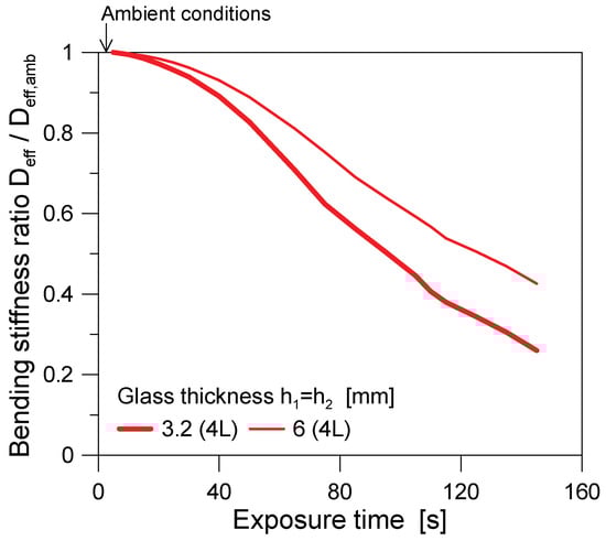
Figure 16.
Bending stiffness ratio as a function of the exposure time (ABAQUS).
Accordingly, whilst the measured thermal gradients are still not associated with any possible expected thermal shock for the tempered glass layers (i.e., see Figure 11a and Table 2), an important modification to and degradation of the load-bearing capacity for the examined BIPV systems can be observed from the presented results. In this sense, the reported outcomes confirm the possible vulnerability of BIPV systems to elevated temperatures but also show a major sensitivity to many geometrical and mechanical parameters, and thus emphasize the need of a robust multidisciplinary study to assess their safety and optimal use as integrated building components.
6. Conclusions and Future Studies
A numerical study was presented in this paper to assess the mechanical performance and load-bearing capacity of glass–glass photovoltaic (PV) modules for building integrated (BIPV) applications when exposed to elevated temperatures and even fire. One particular focus was the expected mechanical and thermo-mechanical phenomena that could impact critical mechanisms in the resisting cross-section, even with still-intact glass panels, in the initial stage of heating (i.e., before glass cracking).
To this end, possible variations in the cross-section geometry (i.e., glass thickness) and mechanical restraints were taken into account, considering a given PV system with four linearly supported edges (4L), two linearly supported edges (2L), and even four-point fixing restraints (4P).
Even when limited to few configurations, the numerical analysis provided evidence of some important effects that could negatively affect the load-bearing capacity of these integrated components. According to the adopted modelling strategy, which was earlier validated in experiments in the literature, the present numerical results pointed out the following:
- Changing the glass thickness (from 3.2 + 3.2 mm to 6 + 6 mm in the present study) can minimally reduce the vulnerability and mechanical loss of capacity for similar systems.
- In particular, due to combined thermo-mechanical phenomena, the increase in glass thickness has no proportional benefits in terms of mechanical response and residual capacity under elevated temperature scenarios.
- Due to the progressive temperature spread in the size and thickness of the resisting cross-section, the associated material degradation primarily affects the encapsulant layers and has major consequences on the corresponding mechanical capacity of the system. Important stiffness reductions were numerically observed for still-moderate temperature gradients.
- The presence of different mechanical restraints (4L, 2L, or 4P, in the present study) is generally associated with minimal effects in terms of temperature spread and increase in the resisting section.
- The maximum effect of different mechanical restraints—for BIPV systems under increasing temperatures—is exploited in terms of a major degradation of the global/effective out-of-plane bending stiffness.
The numerical analysis also pointed out the important modification of typical stress fields that is derived from the temperature spread (and typical material degradation) in the resisting BIPV components. In this sense, the stress peaks in glass tend to migrate towards the mechanical restraints and the coldest regions. Purely from a verification and assessment point of view, such a finding confirms the need for refined and sophisticated calculation tools for glass–glass BIPVs, in which the actual boundary conditions should be effectively taken into account.
Certainly, many more influencing parameters should be taken into account to draw general conclusions and suggestions for BIPV optimization. For example, different materials and cross-section compositions could be associated with similar but not identical observations. Moreover, the aspect ratio of BIPV samples is another key parameter that should be considered, in combination with different “non-ideal” mechanical restraints and layout details that are typical of real applications in buildings.
In this regard, the present study provides an important basis, and additional investigations will be carried out, both experimentally and numerically, to verify the possible consequences of additional parameters of primary interest for the optimal and safe use of BIPVs in constructions (such as aspect ratio and size, as well as composition of the resisting cross-section and type/feature of mechanical restraints).
Author Contributions
Conceptualization, C.B. and Y.W.; methodology, C.B., Y.W. and L.C.; software, C.B., R.D.B. and M.F.; validation, C.B., R.D.B. and M.F.; formal analysis, C.B., R.D.B. and L.C.; resources, C.B. and Y.W.; data curation, R.D.B. and M.F.; writing—original draft preparation, C.B., Y.W., L.C., R.D.B. and M.F.; supervision, C.B. and Y.W.; project administration, C.B. and Y.W.; funding acquisition, C.B. and Y.W. All authors have read and agreed to the published version of the manuscript.
Funding
This research was partly funded by the National Key R&D Program of China (grant number 2023YFE0116700) and the Italian Ministry of Foreign Affairs and International Cooperation (grant number CN24GR03).
Data Availability Statement
The data presented in this study are available on request from the corresponding author. The data are not publicly available due to privacy.
Acknowledgments
This research study was carried out within the framework of the ongoing “3FiRES” Particular Relevance bilateral project (2024–2025). The National Key R&D Program of China and the Italian Ministry of Foreign Affairs and International Cooperation are gratefully acknowledged.
Conflicts of Interest
The authors declare no conflicts of interest.
References
- Maghrabie, H.M.; Abdelkareem, M.A.; Al-Alami, A.H.; Ramadan, M.; Mushtaha, E.; Wilberforce, T.; Olabi, A.G. State-of-the art technologies for Building-Integrated Photovoltaic Systems. Buildings 2021, 11, 383. [Google Scholar] [CrossRef]
- Abojela, Z.R.K.; Desa, M.K.M.; Sabry, A.H. Current prospects of building-integrated solar PV systems and the application of bifacial PVs. Front. Energy Res. 2023, 11, 1164494. [Google Scholar] [CrossRef]
- IEA-PVPS. Building-Integrated Photovoltaics—A Technical Guidebook; Chivelet, M., Frontini, K., Eds.; Routledge: New York, NY, USA, 2025; Available online: https://iea-pvps.org/wp-content/uploads/2025/02/Building-Integrated-Photovoltaics-Technical-Guidebook.pdf (accessed on 30 May 2025).
- Bedon, C.; Zhang, X.; Santos, F.; Honfi, D.; Kozlowski, M.; Arrigoni, M.; Figuli, L.; Lange, D. Performance of structural glass facades under extreme loads-Design methods, existing research, current issues and trends. Constr. Build. Mater. 2018, 163, 921–937. [Google Scholar] [CrossRef]
- El Fouas, C.; Hajji, B.; Gagliano, A.; Tina, G.M.; Aneli, S. Numerical model and experimental validation of the electrical and thermal performances of photovoltaic/thermal plant. Energy Convers. Manag. 2020, 220, 112939. [Google Scholar] [CrossRef]
- Johansson, F.; Gustafsson, B.E.; Stridh, B.; Campana, P.E. 3D-thermal modelling of a bifacial agrivoltaics system: A photovoltaic module perspective. Energy Nexus 2022, 5, 100052. [Google Scholar] [CrossRef]
- Honfi, D.; Sjöström, J.; Bedon, C.; Kozłowski, M. Experimental and Numerical Analysis of Thermo-Mechanical Behaviour of Glass Panes Exposed to Radiant Heatin. Fire 2022, 5, 124. [Google Scholar] [CrossRef]
- Symoens, E.; Van Coile, R.; Belis, J. Behaviour of Different Glass Elements subjected to Elevated Temperatures–State of the Art. Challenging Glass 2020, 7, 4489. [Google Scholar] [CrossRef]
- Möckel, M.; Seel, M.; Schwind, G.; Engelmann, M. Temperature distribution and stress relaxation in glass under high temperature exposition. Glass Struct. Eng. 2025, 10, 11. [Google Scholar] [CrossRef]
- Ko, Y.; Aram, M.; Zhang, X.; Qi, D. Fire safety of building integrated photovoltaic systems: Critical review for codes and standards. Indoor Built Environ. 2022, 32, 25–43. [Google Scholar] [CrossRef]
- Despinasse, M.-C.; Krueger, S. First developments of a new test to evaluate the fire behavior of photovoltaic modules on roofs. Fire Saf. J. 2015, 71, 49–57. [Google Scholar] [CrossRef]
- Stølen, R.; Li, T.; Wingdahl, T.; Steen-Hansen, A. Large- and small-scale fire test of a building integrated photovoltaic (BIPV) façade system. Fire Saf. J. 2024, 144, 104083. [Google Scholar] [CrossRef]
- Huang, Y.-C.; Lee, S.-K.; Chan, C.-C.; Wang, S.-J. Full-scale evaluation of fire-resistant building integrated photovoltaic systems with different installation positions of junction boxes. Indoor Built Environ. 2017, 17, 1259–1271. [Google Scholar] [CrossRef]
- Salmerón-Manzano, E.; Muñoz-Rodríguez, D.; Perea-Moreno, A.-J.; Hernandez-Escobedo, Q.; Manzano-Agugliaro, F. Worldwide scientific landscape on fires in photovoltaic. J. Clean. Prod. 2024, 461, 142614. [Google Scholar] [CrossRef]
- Boddaert, S.; Bonomo, P.; Eder, G.; Fjellgaard Mikalsen, R.; Ishii, H.; Kim, J.-T.; Ko, Y.; Kovács, P.; Li, T.; Olano, X.; et al. Fire Safety of BIPV: International Mapping of Accredited and R&D Facilities in the Context of Codes and Standards. Report IEA-PVPS T15-15:2023 (134 pages). 2023. Available online: https://iea-pvps.org/wp-content/uploads/2023/07/Report_IEA-PVPS_T15-15-2023_Mapping-of-Fire-Safety-Laboratories.pdf (accessed on 10 November 2025).
- Simulia. Abaqus Computer Software; Simulia: Providence, RI, USA, 2024. [Google Scholar]
- Louter, C.; Bedon, C.; Kozłowski, M.; Nussbaumer, A. Structural response of fire-exposed laminated glass beams under sustained loads; exploratory experiments and FE-Simulations. Fire Saf. J. 2021, 123, 103353. [Google Scholar] [CrossRef]
- Bedon, C.; Louter, C. Thermo-mechanical numerical analyses in support of fire endurance assessment of ordinary soda-lime structural glass elements. J. Struct. Fire Eng. 2023, 14, 522–546. [Google Scholar] [CrossRef]
- Kozlowski, M.; Bedon, C. Sensitivity to input parameters of failure detection methods for out-of-plane loaded glass panels in fire. Fire 2021, 4, 5. [Google Scholar] [CrossRef]
- Wang, Y.; Li, X.; Bisby, L. Comparative study of thermal breakage of annealed and tempered glazing with different thicknesses under uniform radiation conditions. Fire Saf. J. 2023, 140, 103867. [Google Scholar] [CrossRef]
- Wang, Y.; Xiao, C.; Bedon, C. Performance of photovoltaic panels with different inclinations under uniform thermal loading. Int. J. Therm. Sci. 2025, 208, 109489. [Google Scholar] [CrossRef]
- Bedon, C.; Veronese, L.; Del Bello, R.; Cella, N.; Wang, Y. Numerical Simulation of Thermal Shock for Glass-Glass BIPVs in Fire: Gaps and Challenges. In Fire Safety Engineering-Measures, Policies, and Applications; Bedon, C., Lucherini, A., Stochino, F., Eds.; Books on Demand: Norderstedt, Germany, 2025. [Google Scholar] [CrossRef]
- WSong, J.R.; Tippabhotla, S.K.; Tay, A.A.O.; Budiman, A.S. Numerical Simulation of the Evolution of Stress in Solar Cells During the Entire Manufacturing Cycle of a Conventional Silicon Wafer Based Photovoltaic Laminate. IEEE J. Photovolt. 2018, 8, 210–217. [Google Scholar]
- MSiddiqui, U.; Arif, A.F.M.; Kelley, L.; Dobowsky, S. Three-dimensional thermal modelling of a photovoltaic module under varying conditions. Sol. Energy 2012, 86, 2620–2631. [Google Scholar] [CrossRef]
- Özkalay, E.; Friesen, G.; Caccivio, M.; Bonomo, P.; Fairbrother, A.; Ballif, C.; Virtuani, A. Operating temperatures and diurnal temperature variations of modules installed in open-rack and typical BIPV configurations. IEEE J. Photovolt. 2022, 12, 133–140. [Google Scholar] [CrossRef]
- Lamaamar, I.; Tilioua, A.; Alaoui, M.A.H. Thermal performance analysis of a poly c-Si PV module under semi-arid conditions. Mater. Sci. Energy Technol. 2022, 5, 243–251. [Google Scholar] [CrossRef]
- Limane, B.; Ould-Lahoucine, C.; Diaf, S. Modeling and simulation of the thermal behavior and electrical performance of PV modules under different environment and operating conditions. Renew. Energy 2023, 219, 119420. [Google Scholar] [CrossRef]
- Zhou, J.-C.; Zhang, Z.; Liu, H.-J.; Yi, Q. Temperature distribution and back sheet role of polycrystalline silicon photovoltaic module. Appl. Therm. Eng. 2017, 111, 1296–1303. [Google Scholar] [CrossRef]
- Bosco, N.; Silverman, T.J.; Kurtz, S.R. The influence of PV module materials and design on solder joint thermal fatigue durability. IEEE J. Photovolt. 2016, 6, 1407–1412. [Google Scholar] [CrossRef]
- Lindholm, D.; Li, H.; Otnes, G.; Cattaneo, G.; Foss, S.E.; Fjaer, H. Thermomechanical fatigue of solder joint and interconnect ribbon: Impact of low lamination temperature. In Proceedings of the EU PVSEC 2021–38th European Photovoltaic Solar Energy Conference and Exhibition, Online, 6–10 September 2021; pp. 622–626. [Google Scholar]
- Dietrich, S.; Pander, M.; Sander, M.; Shulze, S.-H.; Ebert, M. Mechanical and thermo-mechanical assessment of encapsulated solar cells by Finite-Element simulation. In Proceedings of the SPIE–The International Society for Optical Engineering–Reliability of Photovoltaic Cells, Modules, Components and Systems III, San Diego, CA, USA, 1–5 August 2010. [Google Scholar]
- Noh, Y.; Lee, J. Building-integrated photovoltaic applied Bi-facial photovoltaic module structural design. Solae Energy Mater. Sol. Cells 2024, 269, 112758. [Google Scholar] [CrossRef]
- Wang, Y.; Xie, Q.; Zhang, Y.; Wang, Q.; Sun, J. Sensitivity analysis of influencing factors on glass façade breakage in fire. Fire Saf. J. 2018, 98, 38–47. [Google Scholar] [CrossRef]
- Bedon, C. Structural Glass Systems under Fire: Overview of Design Issues, Experimental Research, and Developments. Adv. Civ. Eng. 2018, 2017, 2120570. [Google Scholar] [CrossRef]
- Sabsabi, A.; Youssef, M.A.; El-Fitiany, S.F.; Vedrtnam, A. Simplified structural analysis of framed ordinary non-tempered glass panels during fire exposure. Fire Saf. J. 2021, 122, 103357. [Google Scholar] [CrossRef]
- El-Din, N.M.S.; Sabaa, M.W. Thermal degradation of poly(vinyl butyral) laminated safety glass. Polym. Degrad. Stab. 1995, 47, 238–288. [Google Scholar] [CrossRef]
- Pelayo, F.; Lamela-Rey, M.J.; Muniz-Calvente, M.; Lopez-Aenlle, M.; Alvarez-Vazquez, A.; Fernandez-Canteli, A. Study of the time-temperature-dependent behaviour of PVB: Application to laminated glass elements. Thin-Walled Struct. 2017, 119, 324–331. [Google Scholar] [CrossRef]
- Suwen, C.; Xing, C.; Xiqiang, W. The mechanical behaviour of polyvinyl butyral at intermediate strain rates and different temperatures. Constr. Build. Mater. 2018, 182, 66–79. [Google Scholar] [CrossRef]
- Li, Y.; Xie, L.; Zhang, T.; Wu, Y.; Sun, Y.; Ni, Z.; Zhang, J.; He, B.; Zhao, P. Mechanical analysis of photovoltaic panels with various boundary conditions. Renew. Energy 2020, 145, 242–260. [Google Scholar] [CrossRef]
- Hartley, J.Y.; Owen-Bellini, M.; Truman, T.; Maes, A.; Elce, E.; Ward, A.; Khraishi, T.; Robert, S.A. Effects of photovoltaic module materials and design on module deformation under load. IEEE J. Photovolt. 2020, 10, 838–843. [Google Scholar] [CrossRef]
- Bedon, C.; Pavan Massi, A. Non-destructive vibration-based monitoring analysis of PV modules with encapsulant degradation by frequency change. Measurement 2024, 236, 115096. [Google Scholar] [CrossRef]
- ISO 834-1:2020; Fire-Resistance Tests–Elements of Building Construction. International Organization of Standardization (ISO): Geneve, Switzerland, 2020.
- Sahli, M.; Correia, J.P.M.; Ahzi, S.; Touchal, S. Thermomechanical investigation of PV panels behaviour under NOCT conditions. In Proceedings of the IESEC–International Renewable and Sustainable Energy Conference 2017, Tangier, Morocco, 4–7 December 2017. [Google Scholar] [CrossRef]
- Evans, D.L. Simplified method for predicting photovoltaic array output. Sol. Energy 1981, 27, 555–560. [Google Scholar] [CrossRef]
- Beinert, A.J.; Leidl, R.; Sommeling, P.; Eitner, U.; Aktaa, J. FEM-Based development of novel back contact PV modules with ultra-thin solar cells. In Proceedings of the 33rd European Photovoltaic Solar Energy Conference, Amsterdam, The Netherlands, 25–29 September 2017. [Google Scholar]
- Jia, Y.; Zhang, J. Thermal conductivity of ethylene-vinyl acetate copolymers with different vinyl acetate contents dependent on temperature and crystallinity. Thermochim. Acta 2022, 708, 179141. [Google Scholar] [CrossRef]
- Desai, P.D. Thermodynamic properties of iron and silicon. J. Phys. Chem. Ref. Data 1985, 15, 967–983. [Google Scholar] [CrossRef]
- Morris, R.G.; Hust, J.G. Thermal conductivity measurements of silicon from 30° to 425 °C. Phys. Rev. 1961, 14, 1426–1430. [Google Scholar] [CrossRef]
- Liu, Z. Temperature-dependent elastic constants and Young’s modulus of silicon single crystal. In Proceedings of the Mechanical Engineering Design of Synchrotron Radiation Equipment and Instrumentation (MEDSI2020), Chicago, IL, USA, 26–29 July 2021. [Google Scholar] [CrossRef]
- Zhao, L.; Maynadier, A.; Nelias, D. Stiffness and fracture analysis of photovoltaic grade silicon plates. Int. J. Solids Struct. 2016, 97–98, 355–369. [Google Scholar] [CrossRef]
- Salama, A.M.; Rowe, W.M.; Yasui, R.K. Stress Analysis and Design of Silicon Solar Cell Arrays and Related Material Properties; JPL Technical Report 32-1552; Jet Propulsion Laboratory, California Institute of Technology: Flintridge, CA, USA, 1972. [Google Scholar]
- Vosteen, L.F. Effect of Temperature on Dynamic Modulus of Elasticity of Some Structural Alloys; NACA TN 4348; Technical Note 4348; National Advisory Committee of Aeronautics: Washington, DC, USA, 1958. [Google Scholar]
- Doležel, I.; Karban, P.; Kropík, P.; Pánek, D. Accurate control of position by induction-heating produced thermoelasticity. IEEE Trans. Magn. 2010, 46, 2888–2891. [Google Scholar] [CrossRef]
- prEN Thstr:2004; Glass in Building: Thermal Stress Calculation Method. European Committee for Standardization (CEN): Brussels, Belgium, 2014.
- Galuppi, L.; Franco, A.; Bedon, C. Architectural Glass under Climatic Actions and Fire: Review of State of the Art, Open Problems and Future Perspectives. Buildings 2024, 13, 939. [Google Scholar] [CrossRef]
Disclaimer/Publisher’s Note: The statements, opinions and data contained in all publications are solely those of the individual author(s) and contributor(s) and not of MDPI and/or the editor(s). MDPI and/or the editor(s) disclaim responsibility for any injury to people or property resulting from any ideas, methods, instructions or products referred to in the content. |
© 2025 by the authors. Licensee MDPI, Basel, Switzerland. This article is an open access article distributed under the terms and conditions of the Creative Commons Attribution (CC BY) license (https://creativecommons.org/licenses/by/4.0/).