1. Introduction
The modern energy industry is developing under a dual challenge: the necessity to increase the efficiency of conventional energy resources and the simultaneous need to reduce greenhouse gas emissions and mitigate environmental impacts. Hydrocarbon fuels still dominate the global energy mix, making the improvement of energy efficiency not only an economic but also a strategic imperative.
A considerable share of the energy released during fuel combustion or the operation of high-temperature systems is lost as low- and medium-temperature heat. These waste-heat streams—such as exhaust gases from turbines and boilers, or heat from industrial cooling and process systems—often represent 40–50% of the total supplied energy [
1,
2], constituting a valuable but underutilized resource. Recovering and converting this energy into useful work is therefore one of the key directions in modern energy development.
For industrial facilities, waste-heat recovery reduces specific fuel consumption and production costs; for power utilities, it increases the overall efficiency of generating units. Globally, increasing attention is being paid to technologies that can transform even low-grade heat into electricity or mechanical power, thereby improving energy efficiency and reducing environmental impact.
Traditional steam-based Rankine cycles are constrained by pressure and temperature limitations, which make them inefficient for low- and medium-temperature sources. Consequently, closed thermodynamic cycles employing low-boiling working fluids—such as the Organic Rankine Cycle (ORC) and the supercritical CO
2 (s-CO
2) Brayton cycle—have emerged as promising alternatives [
3,
4,
5]. These cycles enable effective energy conversion from previously wasted low-potential heat. The ORC is well suited for low- and moderate-temperature applications, while the s-CO
2 cycle demonstrates higher efficiency in the upper temperature range due to favorable thermophysical properties near the critical point [
6].
A particularly promising approach is the cascade (combined) heat-recovery configuration, where the high-temperature part of the heat flow is utilized in an s-CO
2 recompression loop and the residual heat is recovered by an ORC subcycle [
7]. This arrangement broadens the usable temperature range, reduces exergy losses, and improves overall system efficiency. The overall performance of such hybrid cycles is primarily determined by the characteristics of the heat exchangers that couple these thermodynamic loops.
Heat exchangers contribute significantly to the total capital cost of these installations. Their geometry, surface type, material selection, and manufacturing technology (brazing, welding, or diffusion bonding) directly determine the heat transfer effectiveness, pressure drop, mass, and maintainability. As a result, the optimization of heat exchangers must consider not only thermal and hydraulic parameters but also structural and economic constraints.
In ORC systems, the principal heat exchangers include the evaporator (often combining economizer and superheater sections), the condenser, and the regenerator. Evaporators are commonly designed as two-pass shell-and-tube reboilers, where the hot stream flows inside the tubes and the working fluid evaporates in the shell side. Economizers and superheaters are traditionally shell-and-tube devices due to their mechanical reliability, although studies have demonstrated that sectional and brazed-plate configurations can reduce metal consumption, provided that the pressure difference remains below about 3.5 MPa [
8,
9].
The design of condensers strongly depends on the cooling medium. Water-cooled systems typically employ shell-and-tube designs, while air-cooled condensers (ACCs)—consisting of finned-tube bundles—are used when water is unavailable. Owing to the low heat-transfer coefficient of air, extended surfaces and forced convection are required to achieve sufficient heat rejection. Although these designs are reliable, their large size and high material demand significantly increase capital cost [
10].
The regenerator plays a crucial role in defining the efficiency of an ORC plant, as it reduces external heat demand and enhances the thermodynamic performance of the cycle. Shell-and-tube and plate-type regenerators are the most widespread, but both have limitations: the former cannot maintain very small temperature differences, and the latter is limited in its allowable pressure and flow ranges [
11]. Hybrid plate-fin or plate-tubular designs are therefore gaining attention, combining improved compactness with acceptable mechanical strength.
For s-CO
2 Brayton cycles, the situation is even more demanding. Large pressure differentials (up to 30 MPa) and strong property variations near the critical point (
Figure 1) impose strict design constraints [
12]. Shell-and-tube and double-pipe exchangers can withstand these pressures but have excessive size and weight, while compact printed circuit heat exchangers (PCHEs) offer much higher surface density and pressure resistance. Extensive numerical and experimental studies [
13,
14,
15] have demonstrated the advantages of PCHEs in high-pressure CO
2 applications, including enhanced compactness, structural reliability, and thermal effectiveness. PCHEs consist of stacks of chemically etched plates joined by diffusion bonding, providing high structural integrity and exceptional thermal compactness. However, their manufacturing complexity and cost require careful techno-economic optimization.
Thus, the development of efficient and economically feasible heat exchangers for low-boiling working fluids-based systems involves reconciling multiple, often competing objectives: maximizing heat transfer, minimizing pressure losses, ensuring mechanical reliability, and reducing material and manufacturing costs. Achieving this balance demands a systematic methodology that integrates thermodynamic modeling, hydraulic analysis, and cost evaluation. Foundational design frameworks [
16,
17,
18,
19] have established generalized principles for heat exchanger sizing, selection, and fabrication for both conventional and compact geometries. These works form the basis for the mechanical and applicability filters used in the present study.
Alongside thermal performance, economic optimization has become a central direction in heat exchanger research. Numerous optimization studies [
20,
21,
22] have applied metaheuristic algorithms such as cuckoo-search and genetic methods to minimize total annual cost, confirming that geometry and surface type significantly influence investment and operating expenditures. For example, optimization algorithms based on evolutionary or heuristic methods have been successfully applied to minimize the total annual cost of shell-and-tube exchangers. These studies emphasize that the selection of geometry and surface type directly influences both investment and operational efficiency [
23,
24]. Such methods provide an essential background for the cost-driven optimization framework adopted in this paper.
In the field of ORC and s-CO
2 cycles, recent research [
25,
26,
27,
28,
29,
30,
31] has extended the techno-economic perspective to system-level analyses. These works demonstrate that heat-exchanger configuration, material choice, and surface geometry substantially affect cycle efficiency, component compactness, and overall cost performance. Investigations of combined and low-temperature cycles show that the interdependence between geometry, pressure drop, and thermal effectiveness must be considered simultaneously rather than as separate design stages. This conclusion supports the need for integrated optimization models capable of balancing thermodynamic and economic objectives within a single computational framework.
Despite this progress, existing design methods still often treat mechanical feasibility, manufacturability, and cost evaluation as separate tasks. In practice, real systems require that thermal, hydraulic, and economic aspects be optimized together under the constraints of pressure, temperature, material strength, and fabrication limits. Bridging this methodological gap is a prerequisite for the rational selection of heat exchanger type and configuration for next-generation energy systems employing low-boiling working fluids.
The objective of this study is to develop and validate a unified techno-economic optimization methodology for heat exchangers operating with low-boiling working fluids in ORC and s-CO2 cycles. The proposed framework combines multi-parameter optimization of geometric and hydraulic variables with applicability filters derived from mechanical design standards and manufacturing constraints. It enables the identification of configurations that minimize total costs (CAPEX + OPEX) while ensuring the required thermal performance and mechanical reliability.
The novelty of the present research lies in the integration of thermal–hydraulic modeling and cost evaluation within a single optimization environment. The developed methodology captures the trade-offs between heat-transfer performance, pressure drop, and material usage across different exchanger types—fin-and-tube, shell-and-tube, and printed-circuit designs—for a broad range of ORC and s-CO2 operating conditions, including near-critical regimes. This comprehensive approach bridges the gap between theoretical design correlations and practical cost drivers (materials, fabrication, and energy price), providing actionable guidelines for the development of high-efficiency, cost-effective heat exchangers for low-boiling working-fluid energy systems.
2. Materials and Methods
The object of this study is a system of heat exchangers integrated into a combined heat and power cycle employing low-boiling working fluids. The system includes a primary recompression s-CO
2 Brayton loop and a secondary Organic Rankine Cycle (ORC) [
2]. Waste gases with a low content of corrosive or aggressive components, entering at temperatures of 150–550 °C and a typical mass flow rate of approximately 100 kg/s, are considered the hot source.
Within this configuration, the high-temperature portion of the heat is first extracted in the CO2 heater heat exchanger (utilizer). Subsequent deep regeneration occurs inside the CO2 circuit through the high- and low-temperature regenerators (HTR and LTR), while the remaining heat is transferred to the ORC loop through its own utilizer.
The subject of optimization is the design of the key heat exchangers in this system—namely, the utilizers, s-CO2 regenerators, and the ORC regenerator. For each unit, the design parameters such as channel and tube diameters, tube-sheet pitches, and fin geometries are varied, while constraints on pressure, temperature, and minimum temperature difference are satisfied. The objective function is to minimize the total production and operating costs while ensuring a specified thermal load and permissible pressure losses.
To properly formulate the optimization problem, boundary parameters of the heat-exchange processes were defined, including fluid inlet temperatures and pressures, as well as the working fluids used. These data—presented in
Table 1 and
Table 2—cover a range of operating conditions typical of medium-scale industrial waste-heat power plants. Temperature and pressure values were derived from published thermodynamic studies of combined cycles and from design data of existing power units. This approach enables the use of a representative and generalized parameter set, avoiding an in-depth analysis of specific circuits while maintaining the versatility and reproducibility of the modeling results.
Since the primary objective of the study is to improve the technical and economic performance of new heat exchangers operating under specific conditions (pressure, temperature, and flow rate) for low-boiling fluids, while accounting for accepted external conditions (material and energy prices, etc.), with the goal of reducing the cost of electricity generation at power plants, the total cost of heat-exchanger production and operation was chosen as the optimization criterion. The key design characteristics of the heat exchangers, including the type of heating surface, channel geometry, and heat-transfer enhancers, were treated as decision variables. The values of external condition factors influencing the selection of design characteristics for prospective power plants are summarized in
Table 3.
The developed methodology is an algorithm for enumerating and optimizing design solutions, implemented in the form of a block diagram (
Figure 2), as well as a set of databases of limitations of fluids parameters (
Table 4), thermophysical properties of fluids, correlation dependencies of the thermal–hydraulic characteristics of channels on operating parameters, and physical and cost characteristics of materials (
Table 5).
Table 3.
External condition factors for heat-exchanger design selection.
Table 3.
External condition factors for heat-exchanger design selection.
| Factor | Range Values | Source Data | Influence | Accounting in the Present Research |
|---|
| Prices of electricity | 1–100 $/MWh | Electricity tariffs | Determines the costs of pumping the fluids and influences the choice of the channel hydraulic resistance. | 30$/MWh |
| Price of materials | see Table 5 | Supplier catalogues (RUSAL, Severstal, NLMK). | Affects the choice of material and, accordingly, manufacturing technology. | see Table 5 |
| Required term services equipment | 20–60 years | Standards (GOST, ASME), operational statistics | Defines requirements for corrosion resistance, wear resistance and maintainability. | 25 years old |
| Tariffs on maintenance | 1–20% of CAPEX/year | Reports service companies | Affects the choice of design (disassemble or brazed heat exchangers), accessibility for repair. | 5% |
| State subsidies. | 10–50% of CAPEX | Stimulating state programs | Affects the economic feasibility of using high-tech solutions. | Not were taken into account |
| Compactness requirements. | 0.5–2500 m2/m3 | Standards, project specifications. | Imposes restrictions on the use of some designs | Not were taken into account |
Table 4.
Limiting factors for the selection of HE designs [
16,
17].
Table 4.
Limiting factors for the selection of HE designs [
16,
17].
| View Designs | Tmax, °C | Tmin, °C | Pmax, MPa | Pmin, MPa | ΔP1–2 > 3.5 MPa | Phase Change | G1/G2 [vol.] > 10 |
|---|
| Shell-and-tube HE | 500 | −20 | 60 | 0.001 | + | + | + |
| Double-pipe HE | 600 | −100 | 95 | 0.001 | + | + | − |
| Spiral-tube HE | 450 | −20 | 20 | 0.01 | + | + | − |
| Finned tubes HE | 600 | −20 | 30 | 0.01 | + | + | + |
| Plate HE | 200 | −50 | 3.5 | 0.1 | − | − | − |
| Finned plates HE | 200 | −150 | 1 | 0.1 | − | − | − |
| Spiral-plate HE | 200 | −50 | 2.5 | 0.1 | − | − | − |
| PCHE | 700 | −150 | 60 | 0.001 | + | − | + |
Table 5.
Physical and cost characteristics of materials and technologies for manufacturing HE.
Table 5.
Physical and cost characteristics of materials and technologies for manufacturing HE.
| Design | Material | Limit Yield Strength, MPa | Density, kg/m3 | Max Working Temp., °C | Specific Price of Materials ($/kg) | Specific Price of Manufacturing ($/kg) | Key Technological Operations |
|---|
| STHE | Carbon steel | 200–250 | 7900–8000 | 350–400 | 1 | 1.5–1.8 | Manufacturing and welding of the shell, flaring and fastening of pipes, sealing of joints, mechanical processing |
| Stainless steel steel | 210–220 | 7900–8000 | 600–800 | 3 | 4–6 | Cutting and welding of stainless-steel housing elements and pipes, thorough surface preparation and cleaning, weld quality control, pipe flaring, and sealing |
| DPHE | Carbon steel | 200–250 | 7900–8000 | 350–400 | 1 | 0.4–1.2 | Cutting pipes, their coaxial assembly and fixation, welding and sealing of joints, minimal amount of mechanical processing |
| PCHE | Nickel alloys | 350–550 | 8450–8900 | 950–1100 | 8 | 12–20 | Photochemical etching or precision mechanical processing of channels, assembly of a plate package, diffusion bonding under pressure and temperature, subsequent tightness testing |
| Stainless steel | 210–220 | 7900–8000 | 600–800 | 3 | 7–13 |
| Plate-finned-tubes HE | Aluminum (plates) | 100–200 | 2700 | 150–250 | 1.5 | 2.5–3.5 | Stamping of plates with channels, soldering, geometry control |
| Carbon steel (pipes) | 200–250 | 7900–8000 | 350–400 | 1 | 1.5–2.2 | Cutting and welding pipes, joining them with aluminum plates, applying anti-corrosion coating, and checking for leaks |
| Plate HE | Stainless steel | 210–220 | 7900–8000 | 600–800 | 3 | 1.2–1.5 | Plate stamping, surface cleaning, soldering/package assembly, channel accuracy and tightness control |
The first stage of the algorithm generates a set of potentially suitable heat exchanger types based on operating conditions. Applicability criteria compiled from an analysis of regulatory and reference information (ASME) are used for filtering. A database of heat transfer fluid parameter limitations (based on GOST, TEMA standards, SNiP, etc.) and equipment manufacturer data is provided.
Table 4 lists some limiting parameters for the designs under consideration: maximum temperatures and pressures, the ability to operate under significant pressure differences, phase transitions, large flow rate inequalities between hot and cold streams, etc. If the parameters of a given process exceed the permissible limits for a given design, this option is not considered in subsequent steps. For example, brazed plate units are excluded at required pressures > 3–3.5 MPa, whereas for microchannel PCHEs, the presence of two-phase flow (boiling, condensation) is critical, as it can lead to unpredictable conditions and is therefore not taken into account within the methodology.
A database of the thermophysical properties of heat transfer fluids was compiled using the NIST REFPROP and CoolProp thermophysical properties databases [
32]. Specifically, for low-boiling substances such as CO
2, R124, R236ea, and R134a, the dependences of heat capacity, thermal conductivity, viscosity, and density on temperature and pressure were compiled and systematized.
A database of physical and cost characteristics of materials was compiled using metal science reference books [
33], rolled metal catalogs (RUSAL (Moscow, Russia), NLMK (Lipetsk, Russia), Severstal (Cherepovets, Russia)), and supplier quotes. For each material (carbon steel, stainless steel, titanium alloys, nickel alloys), mechanical properties (yield strength, density) and cost were specified, taking into account market fluctuations. Data on production costs (welding, stamping, soldering) were taken from machine-building company reports and manufacturing standards.
All databases were verified by comparison with real heat exchanger designs for industrial power plants.
At the next stage of the algorithm, parametric optimization of geometric characteristics is performed for each remaining design variant. The algorithm sequentially goes through combinations of the main parameters: tube or channel diameter, fin pitch and height (if applicable), tube pitches (for shell-and-tube and plate-finned-tubes devices), number of channels or tubes, wall thickness, etc. For each combination, a full device calculation is performed, including: (1) thermal calculation—determination of the transferred thermal power under given boundary conditions (flow temperatures) and calculation of the required heat exchange surface to ensure heat balance; (2) hydraulic calculation—calculation of pressure losses of flows at the inlet/outlet of the device; (3) mechanical calculation—assessment of the required thicknesses of heat exchange surfaces and structural elements based on the acting pressures and stress tolerances of materials; (4) layout calculation—determination of the final dimensions of the device (number of modules/sections, weight); (5) calculation of economic indicators—determination of the economic costs of production and operation of the heat exchanger.
Thermal and hydraulic calculations rely on correlations for heat transfer and resistance coefficients specific to each channel type. For example, for flows in round pipes under turbulent conditions, the Dittus—Boelter correlations for the Nusselt number and the Colebrook-White approach for the friction coefficient are used; for microchannels, the Gnielinsky correlation and correlations refined based on experimental data for specific working fluids are used; for finned channels, empirical formulas taking into account the height and pitch of the fins are used, etc. The mechanical module calculates stresses in the channel/pipe walls under internal and external pressure and compares them with the material’s yield strength within a specified margin.
To correctly account for the strong but still continuous variation of thermophysical properties of CO2 in the near-critical region (though not directly at the critical point), a segmented, or zone-wise, calculation procedure was implemented.
In this method, the total heat-transfer duty
Qtot of each heat exchanger is divided into
N elementary zones corresponding to equal increments of heat load or enthalpy:
Within each segment i, the local fluid properties—density ρi, viscosity μi, thermal conductivity λi, and specific heat cp,i—are recalculated from the REFPROP/CoolProp database at the average temperature and pressure of that zone. This allows accurate tracking of the pronounced but smooth gradients of cp(T), λ(T), and μ(T) near the pseudo-critical line, without introducing discontinuities or relying on oversimplified property averaging.
For each segment, the Reynolds and Prandtl numbers are computed, and the local Nusselt number
Nui and friction factor
fi are determined using conventional turbulent-flow correlations (Dittus–Boelter, Gnielinski, or geometry-specific empirical relations). The local heat-transfer coefficient is calculated as
where
Dh is the hydraulic diameter, m.
The total heat-transfer rate and pressure drop are then evaluated by integration over all zones:
where
ki—local overall heat-transfer coefficient, W/m
2/K.
This approach makes it possible to apply well-established empirical correlations outside the immediate critical region while preserving the accuracy of property-dependent effects in the near-critical domain typical of high-pressure CO2 heat exchangers.
A sensitivity analysis performed for different numbers of zones (N = 10, 20, 50, 100) confirmed that results converge rapidly: increasing N above 50 changes the overall Nusselt number and pressure drop by less than 2%.
Hence, the segmented discretization ensures numerical stability and physical consistency of the heat-transfer modeling near, but not exactly at, the critical point.
This methodology—often referred to as the segmental design method or piecewise property integration—has been successfully applied in previous works on supercritical CO
2 recuperators and compact heat exchangers [
34].
In the final step, the apparatus manufacturing costs and the adjusted operating costs are calculated for each calculated combination. Material costs are determined based on the mass of structural elements (pipes, plates, fins) and current prices for the corresponding alloys (carbon steel, stainless steel, titanium, nickel, etc.). The materials database includes strength characteristics (for calculating thicknesses) and the average market price per kilogram, accounting for fluctuations. Capital manufacturing costs also include the cost of manufacturing operations—welding, brazing, and stamping—based on data from machine-building companies and manufacturing standards. Operating costs in the model are primarily related to the energy expended in pumping the working fluid through the apparatus, i.e., they depend on the calculated hydraulic losses (the higher the pressure loss, the greater the required compressor or pump work, equivalent to the energy consumed). Thus, the total cost S is represented as a function of the geometric parameters: reducing the channel dimensions generally improves heat transfer and reduces the required area, but increases hydraulic resistance and, consequently, pumping costs—an optimum exists in each specific case. Furthermore, additional adjustments related to the assessment of maintenance complexity (e.g., the need for periodic cleaning of narrow channels) or service life can be introduced into the calculation of S. However, these factors were not explicitly considered in this study, although they are indirectly reflected through the acceptable designs. S is calculated for all combinations of parameters that pass the strength test and meet the heat transfer requirements. The minimum value of S determines the optimal configuration for a given type of heat exchanger. The minimum values of S are then compared between different design types, thereby identifying the most cost-effective type of device for the given conditions.
To confirm the adequacy of the developed optimization methodology, a verification study was performed comparing the calculated characteristics of representative heat exchangers with catalog data from leading manufacturers. The comparison included shell-and-tube units (Kelvion (Herne, Germany) [
35]), plate-type exchangers (Alfa Laval (Lund, Sweden) [
36]), and printed circuit heat exchangers (Heatric [
37]).
Figure 3 presents the comparison of calculated and reference data in terms of total mass and overall dimensions. The deviations between the modeled and catalog values did not exceed 10–15%, which corresponds to the typical uncertainty range of empirical heat transfer correlations (e.g., Dittus–Boelter, Gnielinski). This confirms the validity of the adopted correlations and the reliability of the developed algorithm for predicting the techno-economic characteristics of heat exchangers under industrial operating conditions.
Capital costs are calculated as the sum of the cost of materials, labor, and technological processes:
where
Smat.—material costs,
$;
Smanuf.—manufacturing cost,
$;
M—mass of the equipment, kg;
smat.—specific material costs,
$/kg;
smanuf.—specific manufacturing cost,
$/kg.
Operating costs include maintenance, energy losses and downtime:
where
Smaint.—maintenance costs,
$/year;
Senergy.—cost of electricity spent on driving the pump/compressor used to pump fluids through the HE,
$/year:
where
,
—electric power of the pump/compressor, caused by the presence of pressure losses of the heating and heated fluids, Watt;
pe.p.—electricity price,
$/Wh;
Q1,
Q2—volumetric flow rates of the heating and heated fluids, m
3/s; Δ
p1, Δ
p2—corresponding pressure drops, Pa;
ηcomp.—efficiency of pump/compressor.
A convenient indicator for comparing the costs of heat exchange equipment of different designs is the specific cost of production and operation of the equipment:
where
Qt is the thermal power of the heat exchanger, W.
To speed up the calculations, global minimization of total costs was carried out using the “basin-hopping” method (a particular branch of the Monte Carlo method), in which local minima are found using the Nelder-Mead algorithm—a method of unconditional optimization of a function of several variables.
To formulate recommendations for selecting the key design characteristics of heat exchangers for advanced energy systems (oxy-fuel, and waste heat recovery) operating with low-boiling working fluids, optimization studies were conducted using the developed methodology. Based on the results of variant calculations, the dependence of the weight, size, and cost characteristics of heat exchangers (waste heat recovery units, carbon dioxide, and freon regenerators) on the hot source temperature was established. Furthermore, the geometric channel dimensions that were determined ensure minimal total costs for heat exchanger production and operation.
3. Results
The application of the methodology to the described scenarios revealed several patterns concerning the influence of cycle conditions (heat source temperature, type of working fluid) on the optimal characteristics of heat exchangers and their cost.
Following a preliminary selection process based on the developed methodology and considering the design limitations of low-grade heat recovery units, significant volumetric flow rates, and increased requirements for protection against gas-side contamination, two design variants were approved for further optimization: a utilizer unit with a staggered bundle of smooth tubes and a utilizer unit with a staggered bundle of finned tubes. This choice was based on their adaptability to high gas flow rates, the ability to provide an extended heat-transfer surface with acceptable aerodynamic losses, adequate strength under low gas-side pressure and moderate pressure on the low-boiling fluid side, as well as maintainability and resistance to carbon formation. At the same time, the finning in a staggered arrangement provides additional intensification of heat transfer on the gas side and a reduction in the required surface area in relation to a smooth-tube bundle, while the basic smooth-tube version retains the advantages of ease of manufacture and cleaning, which is important for long-term operation of waste heat recovery lines.
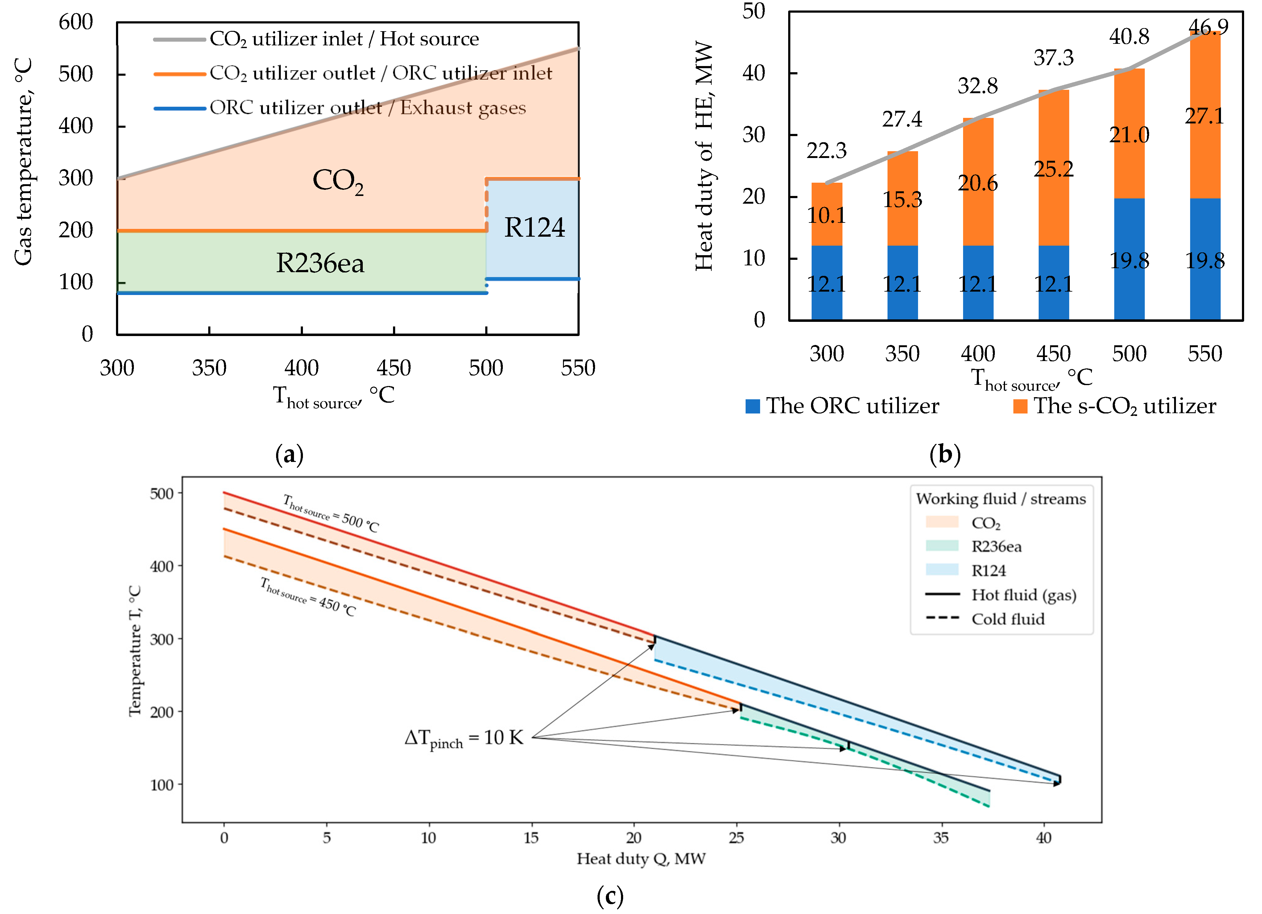
Figure 4 shows how the inlet and outlet gas temperatures of the combined-cycle waste heat exchangers, as well as their thermal power, vary with the hot source temperature (waste gases at the inlet of the CO
2 utilizer)
. The temperatures and types of low-boiling substances used as heated fluids in the waste heat exchangers, indicated in
Figure 4, were selected in accordance with the initial data: for hot source temperatures of 300–450 °C, the optimal working fluid was refrigerant R236ea, and for temperatures of 500–550 °C–R124.
The diagram of the thermal capacity of the waste heat exchangers, shown in
Figure 4b, is constructed for a waste gas mass flow rate of 100 kg/s (this flow rate was chosen as representative for industrial power plants in this study). The observed jump in the capacity of the ORC waste heat exchangers from 12.1 MW to 19.8 MW with increasing hot source temperature is due to a change in the organic working fluid type (and consequently its optimal thermodynamic parameters). The combined heat duty of the CO
2 and ORC waste heat exchangers changes smoothly with changing hot source temperature, since the outlet gas temperature remains at the same level (80–110 °C).
Figure 4c shows the temperature–heat duty (T–Q) diagrams for the ORC heat exchangers using R236ea and R124 as working fluids. These curves illustrate the thermal matching between the waste gas stream and the organic fluids at different hot source temperatures. For hot source temperatures up to about 450 °C, the T–Q profiles of the waste gas and R236ea demonstrate uniform heat transfer with a minimum temperature difference of 10 K along the exchanger. As the hot source temperature increases to 500 °C, switching the working fluid to R124 causes a noticeable relocation of the pinch point, shifting it toward the outlet section of the heat exchanger. This behavior results from the change in thermophysical properties between the two fluids and their differing saturation temperature characteristics.
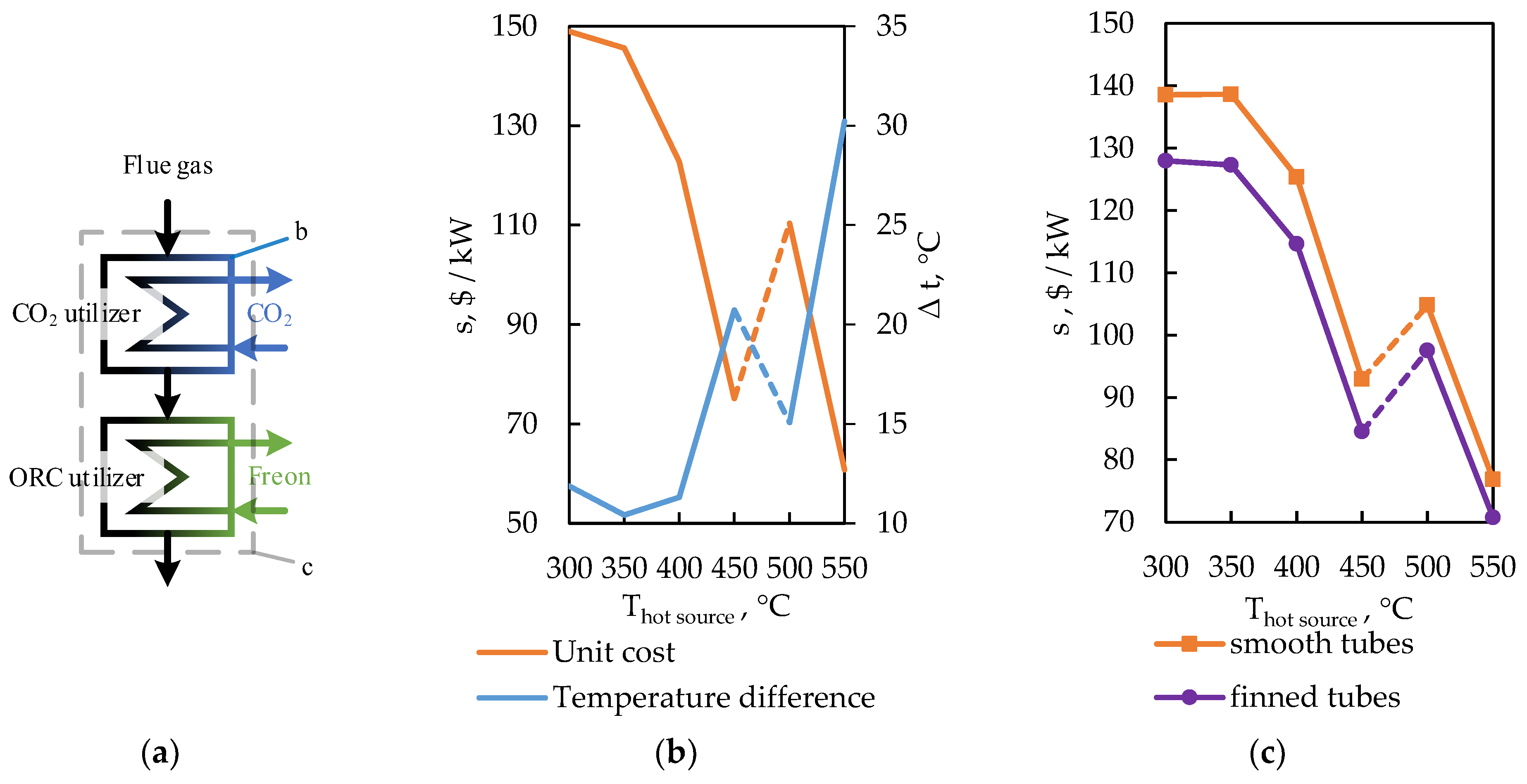
As the hot source temperature increases, the average temperature difference in the waste heat recovery units increases, which leads to a reduction in the required surface area and a decrease in the specific cost (per unit of transmitted power) (
Figure 5a). Thus, for a smooth-tube CO
2 utilizer unit
, it was shown that with an increase in the gas temperature from 350 °C to 550 °C, the average temperature difference increases from ~10 °C to ~30 °C, and the specific total cost is reduced by a factor of approximately 2.45 (from 148.9 to 60.8
$/kW). An analysis of the dependencies of the specific cost of production and operation of combined cycle waste heat recovery units on T
hot source. for various design options of tubes (without fins, with fins), shown in
Figure 5c, indicates that adding fins to the tubes reduces the cost by about 5–8% on average.
Based on the preliminary selection for CO2-cycle regenerators at ultra-high pressures (>25 MPa), three design options were selected for further optimization: PCHE, shell-and-tube HE (STHE) and double-pipe HE (DPHE).
An increase in the hot source temperature reduces the relative cost of heat exchangers, although the effect may not be strictly monotonic due to the associated change in the optimal cycle conditions (
Figure 6). For recompression CO
2 cycle regenerators, when T
hot source is increased from 300 °C to 550 °C, the specific cost of PCHE recuperators increased from 18.32 to 21.4
$/kW (a ~17% increase), while for shell-and-tube recuperators the cost decreased from 36.4 to 33.3
$/kW (~8% decrease, which is associated with the redistribution of thermal loads and CO
2 properties near the critical region).
In the temperature range of 400–450 °C, the minimum specific cost of production and operation of the HTR and LTR occurs for all design types (at T
hot = 350 °C, s = 18.32
$/kW; at 400 °C, 15.01
$/kW; at 450 °C, 14.55
$/kW). This effect is explained by the improvement of the thermophysical properties of the working fluids in this temperature range.
Figure 7 shows how the average temperature difference, heat transfer coefficient, and cold-fluid temperature in the PCHE LTR vary with the hot source temperature. In the hot source temperature range of 400–450 °C, the heat transfer coefficient exhibits a distinct maximum. This is because in this temperature range the heating fluid’s temperature (at a much lower pressure than that of the heated medium) drops by 10–15 °C, approaching its critical point, at which CO2′s heat capacity and thermal conductivity increase sharply (
Figure 7b), thereby increasing the heating medium’s heat transfer coefficient.
Although PCHE recuperators provide the lowest specific cost among all options considered (for the given temperature head and pressure constraints), it is important to emphasize that their overall costs are largely determined by the microchannel geometry and associated flow parameters. The hydraulic diameter plays a key role, simultaneously determining the heat transfer coefficient and the magnitude of hydraulic losses. A smaller diameter reduces the required surface area and mass, but exponentially increases pressure drops and, consequently, operating costs for pumping, while excessively larger channels lead to an increase in surface area and metal consumption. The velocity of the heating medium also has a significant impact, since, through the Reynolds number, it determines the intensity of heat transfer and specific losses, as well as the optimal ratio of hot and cold flow velocities, which in a microchannel matrix has a narrow permissible range due to the identical channel cross-sections.
Figure 8 shows how the cost of etched-channel CO
2 regenerators (G = 100 kg/s, T
hot source = 550 °C) depends on the channel hydraulic diameter and the heating medium’s velocity. For these conditions, the minimum costs of the etched-channel HTR and LTR are
$281,300 and
$349,000, achieved at hydraulic diameters of 0.66 mm and 0.43 mm, respectively.
Although the optimization procedure identified optimal hydraulic diameters in the range of 0.3–0.7 mm for the printed circuit heat exchangers (PCHEs), these values remain within the limits of current manufacturing capabilities. Modern photochemical etching and diffusion-bonding technologies routinely produce channels with characteristic sizes down to 0.2–0.25 mm and wall thicknesses of 0.3–0.5 mm, ensuring structural integrity under pressures exceeding 30 MPa [
38,
39,
40].
The cost of materials and electricity are important factors influencing the optimal design of heat-exchange equipment for low-boiling fluids.
Figure 9 shows how the optimal PCHE channel size and cost vary with material price and electricity price (the HTR and LTR parameters of the recompression CO
2 Brayton cycle for G = 100 kg/s and T
hot source= 550 °C). The dots in the figures indicate the costs under the basic conditions of heat exchange modeling: with a material price of 1.5
$/kg and an electricity price of 30
$/MWh.
According to the calculation results, an increase in the cost of materials leads to a decrease in the optimal channel dimensions, which thereby reducing metal consumption. For example, an increase in the cost of materials to $6/kg at a constant price of electricity of $30/MWh causes the optimal channel diameter to decrease from 0.66 mm to 0.45 mm and raises the total cost from $281,000 to $460,000. In turn, an increase in electricity price leads to higher operating costs due to pressure losses, which in turn increases the optimal channel cross-sectional area. Thus, at a material price of $1.5/kg, an increase in the price of electricity from $30 to $100/MWh leads to an increase in the optimal diameter from 0.66 to 0.95 mm, and the final cost of production and operation increases from $281,000 to $490,000.
Table 6 and
Table 7 present the main results of the calculation options for utilizers and regenerators for combined-cycle waste heat recovery power plants. It was found that, of all the waste heat recovery unit design options considered, PCHE regenerators and finned tube utilizers provide the greatest compactness and the lowest total production and operating costs.
Thus, for a combined cycle with CO2 and an ORC, it has been shown that the most cost-effective design solutions are PCHE regenerators and finned-tube heat exchangers. However, to assess the potential of the organic cycle separately, it is necessary to analyze the operation of its key in-cycle heat exchanger—the regenerator. This device determines the degree of heat recovery in the circuit, influences the thermodynamic efficiency of the cycle, and accounts for a significant portion of its capital and operating costs. Therefore, further research focuses on optimizing the design parameters of the ORC regenerator.
It is also important to emphasize that during the preliminary design selection stage for the ORC regenerator, in addition to the previously considered design solutions, a plate-finned-tubes configuration was included in the list of designs approved for optimization analysis. This expansion of the design pool is due to the inherently lower operating pressures in the ORC regenerator compared to s-CO2 regenerators.
Since a plate-finned-tube regenerator is formed by tube bundles finned by parallel plates, its thermal–hydraulic characteristics are largely determined by the tube sheet geometry. The key parameters are the relative transverse and longitudinal pitch, normalized to the diameter, which simultaneously determine the size of the developed surface and the level of aerodynamic resistance in the intertube space. For fixed materials, tube diameters, and plate gaps, it is the transverse spacing S
1/d and the longitudinal spacing S
2/d that form the primary compromise between heat transfer intensity and pressure losses, and therefore the overall cost of the unit. In this regard, the dependence of the total cost of production and operation of the ORC regenerator (R236ea, T
hot source. = 200 °C, G = 100 kg/s) on the relative steps with other optimized parameters, shown in
Figure 10a demonstrates a clearly defined minimum region of about
$120,000, corresponding to a stable ratio of S
1/S
2 = 1.35.
To clarify this relationship,
Figure 10b,c presents the calculated fields of the Nusselt number (Nu) and the friction factor (f) as functions of the relative transverse and longitudinal tube pitches (S
1/d and S
2/d). It should be noted that for each combination of S
1/d and S
2/d, a separate optimization of other parameters—such as flow regime (Reynolds number) and geometric layout—was performed to ensure comparable operating conditions. The results show that the region corresponding to the minimum total cost in
Figure 10a lies within the area where the heat-transfer intensity is combined with relatively low hydraulic resistance. This confirms that the economic optimum results from the same thermohydraulic balance: an increase in the transverse spacing reduces pressure losses, while an excessive increase in both spacings decreases the heat-transfer coefficients. The obtained optimum ratio S
1/S
2 ≈ 1.3–1.4 therefore represents the most efficient compromise between thermal performance and flow resistance, which remains valid for a wide range of Reynolds numbers and working-fluid properties.
Below, we examine the temperature dependence of the total cost for alternative ORC regenerator designs.
Figure 11 shows the dependence of the production and operating costs of various ORC regenerator designs on the hot source temperature. Data analysis shows that the plate-and-tube design consistently demonstrates lower costs than other types across the entire temperature range studied for all fluid types.
It is significant that increasing the hot source temperature from 150 to 300 °C significantly increases the production and operating costs of all design types: for R236ea, the plate-finned-tube design increases by 4.5 times, the PCHE design increases by 6.5 times, and the shell-and-tube design increases by 5.5 times. This is due to the increase in thermal power (4.7 times), while the average temperature difference between the fluids in this hot-source temperature range remains virtually unchanged. At the same time, the plate-finned-tube design maintains its advantage across the entire temperature range, with the exception of R134a at 150 °C, where it is slightly inferior to the PCHE design.
In
Table 8, the weight, size, and total cost of production and operation of ORC regenerators (G = 100 kg/s) are presented. It can be seen that the most optimal regenerator design is the plate-finned-tube type, but PCHE has smaller dimensions.
In discussing the influence of economic factors, we note the practical significance of these results. For example, for enterprises where the cost of materials (say, high-quality stainless steel or alloy) is high, it makes sense to invest in more complex but material-saving designs—with microchannels, intensive finning, and perhaps more labor-intensive manufacturing. Conversely, if electricity is expensive, the unit will incur significant operating costs due to pumping fluids through excessively narrow channels, and it is preferable to choose a less complex design, even if it requires more metal. Thus, the optimal heat exchanger design may vary across countries or economic conditions: our methodology allows us to take these differences into account at the design stage. This approach is relevant given the volatility of material prices (for example, fluctuations in metal prices) and energy resources.
Finally, it should be emphasized that the achieved reduction in the overall costs of heat exchange equipment directly impacts the cost of energy generated in the power complexes under consideration. Reducing the metal consumption of the equipment and increasing its efficiency (reduced heat loss) makes installations using low-boiling working fluids more economically attractive. This is especially important for heat recovery technologies (ORC, CO2 cycles), the yield of which is sensitive to equipment cost. The results of this study can be used in preliminary feasibility studies of such projects, enabling the selection of an efficient heat exchange unit layout at an early stage. Furthermore, the proposed methodology can be further developed and expanded: for example, by incorporating reliability and service life factors (corrosion, surface fouling), optimizing not only costs but also durability. It is also promising to expand the materials database, taking into account the emergence of new alloys, polymers for medium temperatures, and composites, which may change the optimal choice. However, it is already clear that a systematic approach to design selection using optimization algorithms is a powerful tool that complements engineering experience.


