Abstract
The DC traction power system adopts the track as the return rail. When the track-to-earth insulation in the subway tunnel deteriorates, stray currents will cause electrochemical corrosion to tunnel steel structures and seriously affect the service life and safety of metro tunnels. Stray currents cannot be directly measured and can only be calculated. Therefore, a calculation model with a hollow circular cross-section structure was proposed, and the stray current distribution in tunnel steel structures was calculated. In addition, the effects of different rail-to-ground transition resistances and adjacent buried metallic pipelines on the stray current distribution of the tunnel steel structures were taken into account. The results show that the total amount of stray current dispersed into the tunnel steel structures and soil is similar. The stray current density distribution in each steel tunnel is related to its location. The total stray current carried by the steel structures of the bottom tunnel segment is 102, 15.7 and 3.1 times higher than that of the top, upper and lower side tunnel segments, respectively. The reduction in the transition resistance and increase in the distance of the train from the traction substation increase the total rail leakage current and have a small effect on the percentage distribution of stray current in tunnel structures. The buried metal pipeline parallel to the tunnel has a lower impact on the total stray current leakage, but can reduce the total stray current in steel structures and drainage net, enlarging the positive stray current scope of some tunnel steel bars, further increasing the stray current density on tunnel steel bars. The results of this study can be used to determine the degree of corrosion of the underground steel tunnels and thereby provide support for corrosion prevention.
1. Introduction
Urban subways adopt the DC traction mode, and the power supply voltage is generally selected as 750 V and 1500 V. In the DC traction power supply systems of metro networks, running rails are predominantly utilized as return rails to reduce construction costs and simplify installation processes. This design allows the majority of the return current to flow back to the Traction Power Substations (TPSs) through the rails [1,2]. However, due to prolonged operation and humid tunnel environments, the insulation between the rails and the ground may degrade, causing a portion of the return current to leak into the surrounding structures and form stray currents [3]. These stray currents can lead to severe electrolytic corrosion of buried metallic structures, representing one of the most critical forms of electrochemical corrosion [4]. This significantly compromises the service life of metallic infrastructures [5]. Stray currents cannot be directly measured and can only be calculated. Therefore, only a simulation model that can reflect the actual structure can make the calculation results more reliable. Such a study on stray current distribution in metro tunnel steel structures can be used to determine the corrosion degree of the underground steel tunnels and thereby provide support for corrosion prevention.
Domestic and international research on stray current calculation in the DC power supply system primarily employs simulation and analytical methods. Analytical methods involve establishing mathematical models of the DC return system and focusing on dynamic stray current analysis as train positions change, thereby simulating dynamic variations in rail potential and surface potential [1,2,3,4,5,6,7,8]. To address the high complexity and limited accuracy of existing dynamic simulation systems, researchers such as Wang Huikang and Yang Xiaofeng [9,10] introduced a bidirectional variable resistance module. This module adjusts the longitudinal resistance on both sides of the train to simulate its movement, enabling the dynamic simulation of rail potential and stray currents under various grounding methods and train operational conditions.
Regarding the influence of factors such as transition resistance, insulation damage, and soil topology [11] on stray current distribution, scholars have conducted extensive research using simulation methods. Transition resistance, defined as the resistance per unit length between the rail and the ground, between the rail and structures, or between two conductors, is a critical parameter affecting stray currents in DC traction systems [12,13]. It influences rail potential, pipeline potential, stray current along the drainage network, and DC current distribution at transformer neutral points to varying degrees [14,15,16,17]. In practice, transition resistance is not uniformly distributed and may exhibit localized insulation damage. Xia Nenghong et al. [18,19] developed a segmental distribution model of transition resistance along the rail to study the impact of localized insulation damage on stray current distribution. Their results indicated that the current distribution after rail damage primarily depends on the original rail potential distribution before damage, with stray current leakage in damaged areas being significantly higher than in intact regions.
To evaluate the overall stray current levels in drill-and-blast tunnel sections of DC traction systems, Charalambous et al. [20,21,22] established a 3D model of an open-cut tunnel section, enabling dynamic assessment of stray currents on square tunnel walls, drainage nets, and buried pipelines. They investigated the impact of stray currents generated by regenerative braking on tunnel reinforcement and rail potential. Shield tunnels account for approximately 60% of total metro mileage. Under the influence of DC stray currents, reinforcement bars used to strengthen tunnel structures may corrode, compromising the load-bearing capacity of shield tunnels [23]. Jin Hao et al. developed a corrosion calculation model for reinforcement bars in shield tunnel sections, considering the influence of concrete track beds beneath the rails on stray current distribution. Their study revealed the potential distribution and corrosion patterns of tunnel reinforcement bars under varying input and output current positions [24,25].
A comprehensive review of the domestic and international literature indicates that stray current calculation methods based on circuit equivalent models generally adopt a uniform resistance distribution and struggle to accurately represent the complex environment formed by tunnel steel structures, adjacent reinforced concrete constructions, and buried metallic pipelines. These methods often fail to account for the arrangement of structural reinforcement bars inside and outside the tunnel or consider soil conditions and current field distribution around the tunnel. Most existing stray current simulation models adopting a relatively simplified rectangular structure do not adequately address the impact of the tunnel’s hollow structure on stray current distribution, so the results are insufficient in terms of the accuracy of studying the stray current local distribution of the steel structures inside and outside the tunnel. There is a need to develop specialized calculation models and methods for stray currents in shield tunnels with hollow structures, to study the distribution patterns of metro stray currents in steel structures and surrounding media. To address this gap, this paper proposes a modeling approach for metro stray currents that incorporates the circular cross-section of hollow tunnel structures. It analyzes the distribution of stray currents in tunnel reinforcement bars, rails, and drainage net under varying transition resistances, and investigates the influence of buried metallic pipelines on stray current distribution in tunnel steel structures. The findings provide a foundation for protecting metallic pipelines in metro tunnels from corrosion and ensuring the safety of the power supply.
2. Calculation Model and Methods
The metro DC traction system primarily consists of traction substations, running rails, trains, and other components, as illustrated in Figure 1. Based on the previous work and taking into account the practical engineering conditions [14,26], metro shield tunnels are embedded in soil, with the space above the rails inside the tunnel being air, which does not provide a path for stray current flow. Below the rails lies a concrete layer, within which the drainage network and tunnel reinforcement bars are embedded. Given that the volume of the localized concrete layer is considerably smaller compared to the extensive surrounding soil, in typical grounding engineering practices, for concrete layers that have been buried in soil for extended periods and where the soil moisture content exceeds 20% to 30%, the resistivity of the concrete can be considered equivalent to that of the soil [27]. Consequently, in the model, the region outside the tunnel air is uniformly designated as a soil layer. Subway tunnel and stray current simulation model with hollow circular section structure are showed in Figure 2.
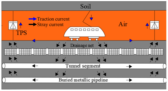
Figure 1.
Schematic of DC railway transit system.
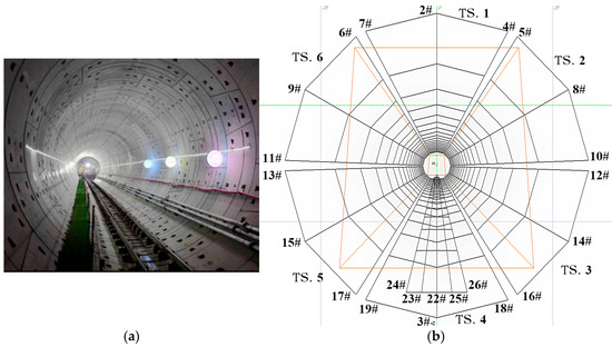
Figure 2.
Subway tunnel and Stray current simulation model with hollow circular section structure: (a) hollow structure in subway tunnel; (b) simulation model.
According to the specification CJJ/T 49-2020 “Technical Standard for Stray Current Corrosion Protection of Urban Metro Systems” [12], the transition resistance to earth for running rails of new lines shall be no less than 15 Ω·km, and that of existing lines shall be no less than 3 Ω·km. When the transition resistance of running rails to earth falls below 0.5 Ω·km, stray current leakage will become extremely severe [14]. To compare the distribution of stray currents on various steel structures under different rail transition resistances, these three scenarios are selected for calculation in this paper.
The metro track employs the widely used 60 kg/m I-shaped rail, which is equivalently modeled as a metallic cylindrical conductor. In practice, the rail is connected to the ground via insulated fasteners. To simulate the transition resistance in the computational model, an insulating layer is applied around the metallic rail conductor.
In the equation, U0 represents the voltage applied between the inner conductor and the outer conductor (V); τ denotes the charge per unit length on the inner conductor (C), ρ is the resistivity of the insulating layer (kΩ·m), R0 is the equivalent radius of the rail (m), h is the thickness of the insulating layer (m), and Rg is the transition resistance (Ω·km).
The simulation parameters for the metro tunnel model are presented in Table 1. The insulating layer thickness is set to 0.01 m, with a resistivity of 98 kΩ·m, corresponding to an equivalent rail-to-ground transition resistance of 3 Ω·km. When the rail-to-ground transition resistance is adjusted to 15 Ω·km and 0.5 Ω·km, the corresponding rail coating resistivities are 450 kΩ·m and 15 kΩ·m, respectively.

Table 1.
Basic model parameters.
3. Distribution of Stray Current in Steel Structures of Subway Tunnels
3.1. Stray Current Density and Rail Potential Distribution of Rails
The train traction current was set at 500 A with a rail-to-earth transition resistance of 3 Ω·km. The stray current density in the rail and the rail potential distribution are obtained as shown in Figure 3. Here, the rail stray current density refers to the amount of stray current flowing out from the rail per unit length, while the rail potential represents the voltage of the rail relative to the grounding point (equivalent to the midpoint between the traction substation and the train in ungrounded systems).
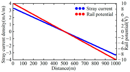
Figure 3.
Stray current distribution and rail potential.
As illustrated in Figure 3, the rail stray current density exhibits a linear distribution, decreasing from 3.30 mA/m to −3.30 mA/m linearly. At the midpoint between the train and the traction substation, the stray current density reaches its minimum value, while the total stray current attains its maximum magnitude with no current outflow or inflow from the rail. Integrating the portion where the rail stray current density exceeds zero yields a total stray current of approximately 833 mA along the rail. The rail potential decreases linearly from 10 V to −10 V, with the maximum potential observed near the train and the minimum near the substation. Within the 0–500 m tunnel section, the rail potential remains positive, forming anodic zones where stray current flows out from the track, inducing electrochemical corrosion. Notably, the stray current density increases progressively toward the train location.
3.2. Stray Current Density Distribution of Tunnel Reinforcement and Drainage Networks
Under unchanged operating conditions, the stray current density distribution in tunnel steel bars is shown in Figure 4. Owing to the symmetrical configuration of the tunnel, only steel bars on one side are selected for analysis. Figure 4 reveals that the stray current distribution exhibits a symmetric pattern centered at the midpoint between the train and the traction substation. Steel bar #8 demonstrates identical stray current behavior to steel bars #2 and #4, while steel bar #14 aligns with steel bar #10. Similarly, steel bars #16 and #18 share the same distribution profile as steel bar #3, differing only in magnitude.
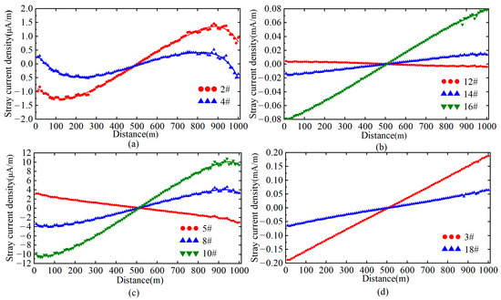
Figure 4.
Stray current distribution in tunnel steel bars. (a) TS.1; (b) TS.3; (c) TS.2; (d) TS.4.
The stray current density distribution in tunnel steel bars correlates with their spatial positions. Steel bars #5 and #12 exhibit stray current directions consistent with the rail, as these bars serve as the topmost structural steel bars above tunnel segments 2 and 3, respectively, providing primary pathways for stray current flow toward adjacent tunnel segments. Steel bars #2, #4, and #8 demonstrate an “S-shaped” stray current density distribution along the tunnel, with density profiles in the 0–500 m and 500–1000 m sections exhibiting central symmetry about the line midpoint.
In the first 500 m tunnel segment, only steel bars #5 and #12 display positive stray current densities. Steel bar #4 shows positive values exclusively within the 0–50 m range, while all other steel bars exhibit negative current densities. Conversely, in the 500–1000 m section, only steel bar #4 presents negative densities between 950 and 1000 m, with the remaining steel bars showing positive values. Excluding the outermost steel bars #2 and #4, other steel bars exhibit progressively increasing stray current densities, reaching maximum values near the traction substation.
Figure 5 illustrates the stray current density distribution in the drainage net beneath the rail. Longitudinal steel bars in the drainage net at different positions follow identical current distribution patterns. The stray current density distribution along drainage net steel bars inversely correlates with rail polarity, where proximity to the substation causes current outflow from the mesh, establishing anodic zones susceptible to corrosion. The 22# drainage net directly beneath the rail carries 154.33 mA, with adjacent 25# and 26# meshes measuring 106.39 mA and 62.34 mA, respectively, demonstrating maximum current concentration directly under the rail that diminishes laterally.
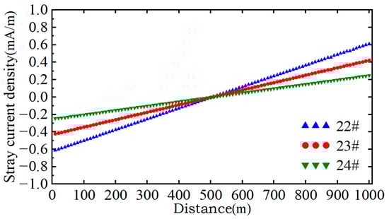
Figure 5.
Stray current distribution in the drainage net.
The total stray current leakage and the aggregate stray current flowing through tunnel steel bars, drainage net, and soil are summarized in Table 2, while the detailed stray current distribution across tunnel steel bars is presented in Table 3. As shown in Table 2, when the rail-to-earth transition resistance is 3 Ω·km, the total stray current leakage from the rail measures 833.566 mA. The drainage net achieves a collection efficiency of 64.53%, with stray currents entering tunnel steel bars and soil exhibiting comparable magnitudes.
Table 2.
Total stray current.
Table 3.
Stray current distribution in tunnel bars.
The stray current magnitude carried by tunnel segments increases progressively from top to bottom. The total stray current in bottom tunnel segment 4 measures 102-fold, 15.7-fold, and 3.1-fold higher than those in top segment 1 and lateral segments 2–3, respectively. The stray currents in these segments account for 0.10%, 0.65%, 3.28%, and 10.20% of the rail’s total leakage current. Transverse connections in each tunnel segment receive 14.3%, 5.1%, 2.1%, and 7.2% of their respective segment’s total current. For lateral and bottom segments, the aggregate stray current in steel bars shows upward-increasing trends vertically, while adjacent bars in neighboring segments exhibit downward-decreasing magnitudes. In the top segment, Steel bar #2 above the rail carries a higher current than bars #4 and #7.
The above analysis corresponds to a rail-to-earth transition resistance of 3 Ω·km. To evaluate resistance impacts, additional operational scenarios with transition resistances of 15 Ω·km and 0.5 Ω·km were simulated while maintaining other parameters. Table 4 compares total stray current leakage across structures under different resistances. The results demonstrate that transition resistance significantly impacts stray current leakage: at 0.5 Ω·km, rail leakage current increases by 2618.5% and 500.7% compared to 15 Ω·km and 3 Ω·km scenarios, respectively, indicating severe leakage conditions. While current density distribution patterns remain consistent across metallic structures, the proportions of stray current allocated to tunnel steel bars, drainage net, and soil maintain fixed ratios relative to total leakage, scaling proportionally with leakage magnitude.
Table 4.
Stray current leakage in different rail-to-earth transition resistances.
4. Influence of Buried Pipelines on the Stray Current Distribution of Steel Structures
Due to the limitations of resource distribution, geographical location and land resources, and the fact that the optimal selection of transmission paths for subways and underground pipelines is extremely similar, in the actual engineering design and construction of subways and underground pipelines, the same “public transmission corridor” is often chosen for laying. The situation of parallelism is quite common. The preliminary work indicates that parallel pipes would not affect the total amount of stray current in the rails. Increasing the distance between the pipes and the rails can reduce the stray current density of the pipes. The greater the angle of intersection between the pipeline and the tunnel, the smaller the proportion of stray current distribution along the pipeline will be compared to that in the horizontal direction. Therefore, this part mainly focuses on the situation of buried pipelines parallel to the tunnel.
Maintaining the operational conditions specified in Section 2 with a rail-to-earth transition resistance of 3 Ω·km, a buried metallic pipeline parallel to the tunnel was added at a horizontal distance of 20 m from the tunnel bottom. The potential and stray current distributions for the rail and pipeline are illustrated in Figure 6.
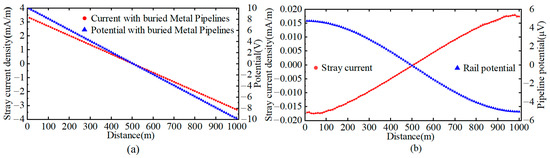
Figure 6.
Stray current distribution and potential in steel structures: (a) rails; (b) buried pipelines.
A comparative analysis of Figure 5 and Figure 6 reveals that the rail potential and stray current distribution remain consistent with scenarios without the pipeline, confirming that the buried pipeline has no impact on the total rail stray current leakage. The pipeline potential decreases from 4.74 µV to −5 µV, three orders of magnitude lower than the rail potential. Similar to the rail, the pipeline potential peaks near the train and reaches its minimum near the substation. The pipeline stray current density increases linearly from −0.017 mA/m to 0.017 mA/m, with a total pipeline current of 5.311 mA, linearly rising between the 100–900 m tunnel sections. Notably, the pipeline current polarity opposes the rail’s: maximum current inflow occurs near the train, while the 0–500 m section near the substation acts as an anodic zone, with current outflow density increasing toward the substation. The rail’s stray current density profile remains unaffected by the pipeline.
As summarized in Table 5, the total stray current in tunnel steel bars decreases by 1.5703 mA (0.18% reduction) compared to the no-pipeline scenario, with the diverted current fully absorbed by the pipeline. Minor variations occur in individual steel bars: currents in bars #5, #6, #12, #13, and #18 increase by 0.1473 mA, 0.2175 mA, 0.152 mA, 0.3219 mA, and 0.004 mA, respectively, while others decrease.
Table 5.
Stray current in tunnel steel bars under two cases.
Figure 7 compares steel bar stray current distributions with and without the pipeline. The most significant influence is observed in the three longitudinal steel bars on tunnel segment 1 (farthest from the rail). For example, Steel bar #2 in the 500–1000 m tunnel section exhibits positive stray currents (anodic zone). Without the pipeline, its current density peaks at 1.456 mA/m near 880 m, but decreases to 0.658 mA/m (54.81% reduction) when the pipeline is present.
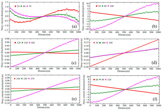
Figure 7.
Distribution of stray currents in tunnel steel bars with or without pipeline: (a) TS.1; (b) TS.2; (c) TS.3; (d) TS.4; (e) TS.5; (f) TS.6.
Figure 8 and Table 6 present stray current densities and allocations for pipeline horizontal distances of 20 m, 50 m, 100 m, 200 m, and 500 m. The pipeline’s presence does not alter total leakage but redistributes percentages among tunnel components. At 20 m, tunnel steel bar currents decrease by 0.17%, and drainage net efficiency drops by 0.03%. The pipeline receives 69.38% of its current from soil, 4.52% from the drainage net, and 26.1% from tunnel steel bars.
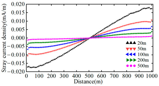
Figure 8.
Stray current distribution in buried pipelines at different distances.
Table 6.
Total stray current leakage at different distances from buried metal pipelines.
As the pipeline distance increases, its current distribution flattens, with the total pipeline current decreasing sharply. From 20 m to 500 m, pipeline current exposure reduces by 95.3%, while drainage net and steel bar currents slightly increase. Beyond 200 m, their currents exceed those in the no-pipeline scenario, with the surplus entirely sourced from soil dispersion.
5. Conclusions
This study established a hollow-structure circular-section tunnel stray current model of a subway in its DC power supply systems. Numerical calculations were performed to analyze stray current distributions in tunnel steel structures under varying transition resistances and to investigate the effects of buried metallic pipelines and train positions. Key findings are summarized as follows:
Under different rail-to-earth transition resistances, the total stray current leakage from the rail varies significantly. However, the proportional distribution of currents among tunnel steel bars, the drainage net, and soil remains unchanged, scaling proportionally with the total leakage magnitude.
In the absence of buried metallic pipelines, the total stray currents leaking into tunnel steel bars and soil are comparable in magnitude. The stray current magnitude carried by tunnel segments increases progressively from top to bottom. Most steel bars exhibit peak stray current densities near the traction substation, while the running rails and the first steel bars on lateral tunnel walls show maximum densities near the train.
The presence of buried metallic pipelines primarily affects steel bars in the top tunnel segment, with minimal impact on the overall stray current distribution or total leakage. Pipelines alter the anodic zones and current densities of certain steel bars, further increasing their stray current densities.
Increasing the distance between the train and the traction substation raises the total stray current leakage but has little effect on the distribution pattern within tunnel steel structures. As the horizontal distance of the buried pipeline increases from 20 m to 500 m, the total stray current on the pipeline decreases significantly, with a reduction of approximately 95.3%.
These findings provide critical insights for optimizing stray current mitigation strategies in metro tunnel design and DC power supply maintenance, particularly in environments with nearby buried infrastructure.
Author Contributions
Conceptualization, Y.F.; Methodology, G.Q.; Software, J.M. and G.Q.; Validation, J.M. and Z.W.; Formal analysis, G.Q.; Investigation, J.M.; Resources, J.M., G.Q. and W.L.; Data curation, Z.W.; Writing—original draft, Z.W.; Writing—review & editing, W.L. and Y.F.; Supervision, Y.F.; Project administration, Y.F.; Visualization, Z.W.; Funding acquisition, Y.F. All authors have read and agreed to the published version of the manuscript.
Funding
This research was funded by Natural Science Foundation of China (NSFC) grant number 51877158.
Data Availability Statement
The original contributions presented in this study are included in the article. Further inquiries can be directed to the corresponding author.
Conflicts of Interest
The authors declare no conflict of interest.
References
- Gu, J.; Yang, X.; Zheng, Q.; Shang, Z.; Zhao, Z. Rail potential and stray current on negative resistance converter traction power system under different grounding schemes and train conditions. Trans. China Electrotech. Soc. 2021, 36, 1703–1717. [Google Scholar] [CrossRef]
- Wang, G.; Pei, X. Three-dimensional finite element simulation of different subway tunnels under stray current fields. J. Railw. Sci. Eng. 2014, 11, 85–91. [Google Scholar] [CrossRef]
- Zhu, F.; Li, J.; Zeng, H.; Qiu, R. Influence of rail-to-ground resistance of urban transit systems on distribution characteristics of stray current. High Volt. Eng. 2018, 44, 2738–2745. [Google Scholar] [CrossRef]
- Cai, Z.; Hao, C. Evaluation of metro stray current corrosion based on finite element model. J. Eng. 2019, 2019, 2216–2265. [Google Scholar] [CrossRef]
- Chen, Z.; Qin, C.; Tang, J.; Zhou, Y. Experiment research of dynamic stray current interference on buried gas pipeline from urban rail transit. J. Nat. Gas Sci. Eng. 2013, 15, 79–81. [Google Scholar] [CrossRef]
- Lin, S.; Zhou, Q.; Lin, X.; Liu, M.; Wang, A. Infinitesimal method based calculation of metro stray current in multiple power supply sections. IEEE Access 2020, 8, 96581–96591. [Google Scholar] [CrossRef]
- Lin, S.; Yang, H.; Zhou, Q.; Wang, A. Evaluation and analysis model of stray current in the metro depot. IEEE Trans. Transp. Electrif. 2021, 7, 1780–1794. [Google Scholar] [CrossRef]
- Liu, W.; Pan, Z.; Zhou, L.; Tang, Y.; Li, S.; Li, Q. Stray current diffusion model of field-circuit coupled DC traction power sup-ply system. High Volt. Eng. 2023, 49, 4594–4603. [Google Scholar] [CrossRef]
- Wang, H.; Yang, X.; Ni, M.; Zheng, Q. Rail potential and stray current dynamic emulator. Trans. China Electrotech. Soc. 2020, 35, 3609–3618. [Google Scholar] [CrossRef]
- Yang, X.; Xue, H.; Zheng, Q. Stray current and rail potential dynamic simulation system based on bidirectional variable resistance module. Trans. China Electrotech. Soc. 2019, 34, 2793–2805. [Google Scholar] [CrossRef]
- Zaboli, A.; Vahidi, B.; Yousefi, S.; Hosseini-Biyouki, M.M. Evaluation and control of stray current in DC electrified railway systems. IEEE Trans. Veh. Technol. 2017, 66, 974–980. [Google Scholar] [CrossRef]
- CJJ/T49-2020; Technical Standard for Stray Current Corrosion Protection in Metro: Ministry of Housing and Urban Rural Development of the People’s Republic of China. China Architecture & Building Press: Beijing, China, 2020.
- Charalambous, C.A. Comprehensive modeling to allow informed calculation of DC traction systems stray current levels. IEEE Trans. Veh. Technol. 2017, 66, 9667–9677. [Google Scholar] [CrossRef]
- Cai, L.; Wang, J.; Fan, Y.; Zhou, M.; Gong, M.; Liu, S. Influence of the track-to-earth resistance of subway on stray current dis-tribution. High Volt. Eng. 2015, 41, 3604–3610. [Google Scholar] [CrossRef]
- Luo, Y.; Liu, J.; Mao, J.; Rong, N.; Wang, N. Analysis of the influence of rail-to-ground resistance on the stray current distribution in a power grid. Power Syst. Clean Energy 2021, 37, 32–40+46. [Google Scholar] [CrossRef]
- Huang, X.; Ma, Q.; Liu, W.; Yin, Y.; Zhou, L. Study on the dynamic interference of stray current in urban traction power supply system on buried metal pipelines. J. Railw. Sci. Eng. 2023, 20, 735–744. [Google Scholar] [CrossRef]
- Wang, K.; Li, W.; Wang, H. Influencing factors and suppression measures of rail potentials under the bilateral power supply. J. Railw. Sci. Eng. 2024, 20, 2465–2475. [Google Scholar] [CrossRef]
- Bao, J.; Li, X.; Xin, Q.; Zhang, L.; Chen, L. Influence of broken insulation pads of rail fasteners in urban rail transit on spatial distribution of stray currents. Adv. Technol. Electr. Eng. Energy 2023, 42, 10–22. [Google Scholar] [CrossRef]
- Xia, N.; Tang, W.; Li, H.; Huang, C.; Xu, X.; Li, F.; Ma, H. Modeling and analysis of dynamic stray current and ground po-tential gradient under partial insulation damage of a metro track. Power Syst. Prot. Control 2023, 51, 53–61. [Google Scholar] [CrossRef]
- Charalambous, C.A.; Aylott, P. Dynamic stray current evaluations on cut-and-cover sections of DC metro systems. IEEE Trans. Veh. Technol. 2014, 63, 3530–3538. [Google Scholar] [CrossRef]
- Charalambous, C.A.; Cotton, I.; Aylott, P. Modeling for preliminary stray current design assessments: The effect of crosstrack regeneration supply. IEEE Trans. Power Deliv. 2013, 28, 1899–1908. [Google Scholar] [CrossRef]
- Charalambous, C.A.; Cotton, I.; Aylott, P.; Kokkinos, N.D. A holistic stray current assessment of bored tunnel sections of DC transit systems. IEEE Trans. Power Deliv. 2013, 28, 1048–1056. [Google Scholar] [CrossRef]
- Yu, S.; Jin, H.; Cao, M. Study on corrosion characteristic of semiring steel plate for strengthening shield tunnel under DC stray current. Constr. Build. Mater. 2022, 347, 128631. [Google Scholar] [CrossRef]
- Jin, H.; Yu, S. Effect of DC stray current on rebar corrosion in cracked segment of shield tunnel. Constr. Build. Mater. 2021, 272, 121646. [Google Scholar] [CrossRef]
- Jin, H.; Yu, K.; Gong, Q.; Zhou, S. Load-carrying capability of shield tunnel damaged by shield shell squeezing action during construction. Thin-Walled Struct. 2018, 132, 69–78. [Google Scholar] [CrossRef]
- Wang, J.; Qian, G.; Fan, Y.; Zhou, M.; Shan, F.; Gong, M. 24-Hour Polarization Potential of Metallic Structures in the Metro Station. Mater. Perform. 2020, 59, 54–58. [Google Scholar] [CrossRef]
- Gong, M. Study on stray current distribution features of adjacent buried metal pipelines in metro system. Railw. Stand. Des. 2023, 67, 161–166. [Google Scholar] [CrossRef]


Disclaimer/Publisher’s Note: The statements, opinions and data contained in all publications are solely those of the individual author(s) and contributor(s) and not of MDPI and/or the editor(s). MDPI and/or the editor(s) disclaim responsibility for any injury to people or property resulting from any ideas, methods, instructions or products referred to in the content. |
© 2025 by the authors. Licensee MDPI, Basel, Switzerland. This article is an open access article distributed under the terms and conditions of the Creative Commons Attribution (CC BY) license (https://creativecommons.org/licenses/by/4.0/).