Abstract
Improving the thermal performance of compact heat exchangers is a key challenge in the development of energy-efficient systems. This work investigates the use of topology optimization to generate novel surface geometries that enhance thermal efficiency specifically in narrow rectangular channels. A physics-based topology optimization software, ToffeeX, has been employed to explore turbulator designs within defined spatial and material constraints. The optimization process has focused on maximizing heat transfer, with particular attention on the effect of solid volumetric fraction. Simulations have been carried out using the CFD tools of the optimization software to evaluate the thermal behavior of the proposed configurations. Among the tested designs, a solid volumetric fraction of 8% has led to the most effective solution, achieving a 25% increase in outlet fluid temperature compared to a conventional ribbed reference configuration. Validation using CFD simulations with another package, OpenFOAM, has confirmed these results, showing consistent trends across methodologies. These findings highlight the potential of combining topology optimization with numerical simulation to develop advanced geometries for heat transfer enhancement. The proposed approach supports the development of more efficient and compact heat exchangers, paving the way for future experimental studies and broader industrial applications.
1. Introduction
Heat exchangers are key components in energy systems and play a crucial role in overall efficiency. With the growth of topology optimization (TO) and additive manufacturing (AM) techniques, the development of new structures for heat exchangers has remarkably increased in recent years [1]. In addition, recent advances in optimization methodologies for heat exchanger design demonstrate considerable potential to improve energy system performance.
The application of optimization methods to heat exchanger networks has been shown to produce remarkable economic benefits, with documented cost reductions approaching 30–40% in certain applications [2], thanks also to energy efficiency improvements. Moreover, the volumetric efficiency of optimized heat exchanger designs represents another significant advancement, with reduced material requirements contributing to the objectives of both economic and environmental sustainability, resulting in an overall reduction in energy consumption [3,4]. So, computational optimization techniques applied to heat transfer systems have yielded substantial efficiency gains across multiple industrial contexts. Moreover, the integration of TO with AM opens new possibilities for the design and production of complex structures [5]. This synergy allows for the creation of even more lightweight, efficient components that maintain structural integrity while reducing material usage [6], addressing global energy challenges [7]. Nonetheless, some manufacturing constraints related to the AM technique could be needed, which introduces further complexity into the design process. Consequently, the TO process should be approached as a multidimensional challenge [8], taking into account both geometric and material constraints, as well as the specific capabilities and limitations of the AM process itself. This is particularly important because AM allows for greater design freedom compared to traditional manufacturing methods, but also requires careful consideration of factors such as printability, material properties, and layer-by-layer fabrication constraints, which could significantly influence the final part manufacturability and performance [9]. Despite advances in recent years, TO is still not a fully robust and universally applicable numerical design technique to determine optimal industrial solutions [10]. Although various methods have shown great potential in various applications [11,12,13,14], they face several challenges, including issues related to computational efficiency, scalability, and the accurate representation of real-world manufacturing processes. As a result, continued research is essential to refine the existing algorithms, improve their computational speed, and validate the outcomes. This is particularly critical for industries that require reliable, repeatable, and cost-effective design solutions, as further advancements in TO could lead to more widespread adoption in industrial practices [15].
At the component level, optimization allows for the creation of novel heat exchanger concepts, and its application on various heat exchanger elements has demonstrated a significant impact on thermal performance parameters [11,16]. Commonly, the TO process for the development of heat exchangers involves several key stages, starting with the definition of the design parameters that govern the performance and structural integrity of the system [17]. This is followed by the application of heat transfer modeling, where the specific thermal characteristics of the heat transfer process are evaluated. Afterward, the optimization process is carried out, during which different configurations and geometries are explored to identify the most effective design. Finally, the results of the optimizations are analyzed to determine the final result [18].
However, a comprehensive TO model for heat exchangers should not only focus on heat transfer characteristics. While conduction, convection, and radiation are crucial in determining the thermal performance, other factors such as pressure drop, flow distribution, and mechanical strength should also be considered in the optimization process [19]. Incorporating these additional quantities, such as pressure loss and flow resistance, allows for a more comprehensive approach to designing heat exchangers, particularly for applications where fluid dynamics and material constraints play a significant role. Thus, depending on the specific requirements of the system, these factors can be weighted and integrated into the optimization model to achieve a more balanced and efficient solution [20,21,22,23].
1.1. State of the Art
Several studies in recent years have increasingly focused on improving the thermal performance of heat exchangers through geometrical optimization and the implementation of flow-disturbing elements.
Primo et al. [24] presented a methodology integrating TO with AM constraints to support innovative product design. This methodology has been applied to a C-clip case study, evaluating topological, lattice, and hybrid approaches. The study has shown that the hybrid approach offers the potential for creating innovative and high-performing structures by combining the advantages of both topological and lattice methods. Lei et al. [25] designed heat sinks using TO for natural convection applications and fabricated them via stereolithography-assisted investment casting. Their designs have been validated experimentally and through simulations, and they have been then compared with conventional pin fin heat sinks. The topology-optimized heat sinks consistently outperformed the reference designs under the conditions for which they have been optimized. This study demonstrates the feasibility and advantages of combining TO with affordable metal casting techniques. Zeng et al. [26] proposed a TO approach for air-cooled microchannel heat sinks, focusing on reducing pressure drop while maintaining thermal performance. They have developed a two-layer 2D model to simplify 3D thermo-fluid simulations, validated with experimental tests. The TO design, featuring non-conventional fins, outperformed traditional straight channel designs, achieving lower junction temperatures and reduced pumping power. The model has also been validated against 3D simulations with minimal temperature differences of lower than 1.1 °C. Pietropaoli et al. [27] developed a 3D TO method for conjugate heat transfer problems, aiming to maximize thermal performance while minimizing pressure losses. The optimization is based on an adjoint Lagrangian approach with impermeability as the design variable. Applied to a straight duct, the method has generated complex internal structures that have enhanced heat transfer via vortical flows. The results have demonstrated the method’s effectiveness and its suitability for AM. Jahan et al. [28] proposed a thermo-fluid TO method for the design of conformal cooling channels and demonstrated its application in an industrial plastic injection mold manufactured via metal AM. Their study have highlighted the potential of coupling thermal and fluid analyses in the design process, enabling efficient heat transfer even with complex geometries. Experimental testing of the optimized 3D-printed core has shown that, despite lower thermal conductivity compared to conventional materials, the part has been functionally effective, with only modest temperature increases. Their results underline the importance of material selection and surface finishing in achieving optimal thermal performance in AM-based cooling systems. Li et al. [29] developed a multi-objective TO method for liquid-cooled heat sinks, balancing thermal performance and pressure drop. Using a porous medium formulation and coupled thermo-fluid simulations, they demonstrated that optimized designs significantly outperform conventional parallel channels in both simulations and experiments, achieving up to 11.7% lower maximum surface temperature and improved thermal uniformity. Yan et al. [30] developed a two-layer thermo-fluid TO model for microchannel heat sinks, reducing computational cost while maintaining accuracy. The model used 2D equations for fluid dynamics and heat transfer, validated against 3D simulations with a maximum temperature error of about 20%. Compared to single-layer models, the two-layer approach have captured more accurately the thermal coupling between the substrate and the thermo-fluid layer. Hu et al. [31] applied a TO approach to the design of electronic cooling microchannels, showing that optimized branched geometries improved heat dissipation and reduced pressure drop under non-uniform heat flux. Their results have highlighted the potential of such designs for effective hot spot management in compact thermal systems. Høghøj et al. [32] proposed a density-based TO method for two-fluid heat exchangers. In particular, the objective has been to maximize heat transfer under a maximum pressure drop constraint for each fluid, using a single design variable. The optimized designs, characterized by complex geometries as micro-villi-like features, have shown significantly improved heat transfer compared to conventional designs. Additionally, the significance of the flow field in the initial design has been emphasized. Ghosh et al. [33] applied TO to the design of internal cooling ducts for gas turbine blades. Specifically, the aim has been to maximize heat transfer while minimizing pressure drop, using a variable permeability method. Applied to serpentine and rectangular channels, optimized geometries have demonstrated improved performance and reduced flow separation. The results of this study have shown that the obtained designs, which are complex lattice-like structures, achieve significantly higher thermal performance compared to baselines and traditional turbulators. Ali et al. [34] investigated the optimal design of rigid vortex generators within a rectangular duct, aiming to enhance local heat transfer while minimizing pressure losses. Their work has employed an adjoint-based optimization approach within a Computational Fluid Dynamics (CFD) framework, leading to the development of winglet configurations tailored to achieve this balance. Hurry et al. [35] focused on improving a NACA profile heat exchanger by integrating novel surface-mounted turbulators. These structures have been designed to intensify flow turbulence and thus improve thermal performance while limiting the associated increase in pressure drop. Dong et al. [16] used 3D TO to design novel fins for natural convection heat transfer, focusing on fin tube heat exchangers used in the nuclear field, in order to enhance the heat transfer efficiency. The optimization has resulted in a new “airfoil-shaped” fin with perforations, mainly in the central and upper areas. The simulation results have shown that the new fin has improved convective heat transfer and reduces thermal resistance over a wide range of conditions. Xuan et al. [36] proposed a novel two-phase fluid TO method for plate heat exchangers. In particular, a new textured plate heat exchanger has been designed, with the aim to enhance heat transfer and flow distribution. Visualization experiments have shown that the optimized structure improves uniform two-phase fluid distribution, eliminating flow dead zones. Furthermore, the optimized plate heat exchanger has exhibited significantly superior overall thermodynamic performance. Navah et al. [37] proposed a 3D TO approach for designing conformal cooling channels in die casting molds, leveraging AM. By solving the Navier–Stokes equations in a porous medium, their method has accounted for complex flow phenomena. The study has shown up to 50% improvement over conventional designs, with strong numerical validation. This approach has demonstrated significant potential for optimizing cooling efficiency in industrial applications. Wang et al. [38] applied TO to design more efficient plate heat exchangers. TO has optimized material distribution for better performance. A 2D model minimizes average temperature, combining heat transfer and fluid flow. The results have shown that TO-optimized exchangers improve heat transfer by 25% and overall performance by 19.85%, despite a slight increase in pressure drop. This has demonstrated TO’s potential for high-performance heat exchangers, with future work to be completed on 3D structures and turbulence. Hu et al. [39] employed TO to design high-performance rib structures in microchannels of varying geometries (straight, wavy, and fan-shaped). TO-generated ribs—trapezoidal, crescent, and droplet-shaped—have demonstrated superior thermal and flow performance. In wavy channels, TO ribs have reduced base temperature by up to 71.4% and have increased the heat transfer coefficient by over 46% compared to square ribs, while also cutting pressure drop by up to 45%. These results have confirmed TO’s effectiveness in producing adaptive, non-intuitive rib geometries that significantly enhance overall thermo-hydraulic performance. Belwadi et al.’s study [40] applied TO to enhance thermal management in cylindrical lithium-ion batteries using phase change materials. The work has focused on optimizing the distribution of thermal conductivity enhancers, like metal fins, to minimize temperature variance within the phase change material. The results have shown that TO-designed structures outperform conventional ones, offering longer operational times, lower temperatures, and a more uniform melting of the phase change material. Yang et al. [41] employed TO to design novel fins for a rectangular parallel plate heat exchanger unit. Specifically, the goal was to significantly enhance thermal performance and efficiency by optimizing material distribution. Using finite element analysis and a 2D model, the method identified complex fin structures that improved heat transfer. Additionally, numerical simulations showed that the topology-optimized fins outperform traditional designs (cylindrical, rectangular, chevron) in both heat transfer (up to 60–70% in Nusselt number) and overall performance, albeit with increased flow resistance. Finally, the resulting innovative fins have effectively disrupted flow, have prevented dead zones, and have been deemed feasible for manufacturing via stamping technology. A comprehensive and thorough description of the most recent advances in the TO field can be found in [1,18,42].
1.2. Motivation of the Work
Despite many works and applications utilizing TO in different fields, the literature lacks studies about TO in high aspect ratio rectangular channels, which are fundamental in many devices and engineering applications where highly efficient thermal management is required, e.g., small-scale and microchannel heat exchangers, thermal control systems for on-Earth, aeronautics, and space applications, and the cooling of fuel cells and automotive batteries, nuclear reactors, and solar collectors. Additionally, these channels are also applicable to a broader range of systems that require extended and thin surfaces for enhanced thermal performance. As a consequence, in the present work, an investigation has been carried out to identify innovative turbulator geometries aimed at enhancing heat transfer in a high aspect ratio rectangular channel, which has already been widely studied both numerically [43,44,45,46] and experimentally [47] by the authors, but only when equipped with traditional turbulators. A topology optimization approach has been applied using the Physics-Driven Generative Design Platform ToffeeX [48], resulting in the creation of novel turbulator designs. Several configurations have been numerically tested to evaluate their thermal performance, and the most promising ones have been further assessed through additional more refined and detailed simulations employing the Reynolds-Averaged Navier–Stokes (RANS) model in OpenFOAM.
A logic flowchart of the work is shown in Figure 1.
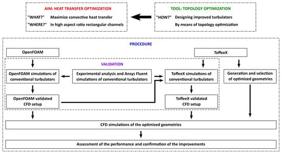
Figure 1.
Overview of the workflow for the project.
2. Materials and Methods
2.1. ToffeeX’s Physics-Driven Generative Design Platform
ToffeeX is a cloud-based computer-aided engineering platform for generative design and topology optimization for heat transfer and fluid dynamics applications. It combines physics numerical simulations and proprietary advanced optimization algorithms to allow users to explore in a relatively fast and automatic way a wide range of design configurations, identifying innovative solutions to maximize thermal and hydraulic performance, complying with user-defined objectives and constraints.
The ToffeeX optimization procedure can be summarized as two steps that are iterated until convergence is reached: during the first step, which can be seen as conceptually analogous to AM, virtual solid is added within the optimization domain (initially filled with virtual fluid) under the constraints set by the user. During the second step, fast CFD simulations are carried out to evaluate the performance of the created geometry, exploiting proprietary techniques in a finite-volume, immersed boundary framework, to make them suitable to obtain a solution on complex geometries in a short time. The results of the CFD simulations are then used to guide the addition or removal of solid in the following iteration of the first step, thus progressively refining the obtained geometry.
The described optimization process promotes the generation of non-intuitive, high-performance geometries that might be difficult or even impossible to conceive using traditional design approaches.
Compared to other Computational Design software packages, e.g., based on adjoint methods (see e.g., [49,50]), which often require specific knowledge and coding skills to create scripts that fully leverage these tools’ capabilities, ToffeeX is designed to be intuitive and fast to learn and use. The software also allows users to integrate geometric and manufacturing constraints in the design process, ensuring that the optimized geometries are not only highly performing from a physical standpoint, but manufacturable using conventional or advanced manufacturing techniques, such as AM—which is best suited for complex 3D shapes as those typically returned by the optimization. These points of strength can make it a valuable asset also for industries where performance and time-to-market are crucial; thus, it is important to fully assess its reliability and performance, which is also one of the aims of the present work.
Mathematical Foundations and Optimization Workflow
The mathematical framework of ToffeeX is based on the continuous description of the material distribution within a given design domain, which enables the optimization of fluid and thermal performance at the same time. This is achieved through the introduction of a scalar design field—the impermeability field a—which interpolates between fluid and solid phases. Such a quantity can vary continuously between zero (representing fluid) and a prescribed maximum (representing solid), enabling the optimizer to determine the optimal material layout in accordance with the specified design objectives and constraints. This approach allows the platform to autonomously generate complex geometries.
The physical behavior of the thermo-fluid system is described by means of RANS equations, as usual when modeling turbulent flows in engineering applications, with the standard model. To account for the effect of the evolving topology within the design region, a Brinkman penalization term [51] is incorporated into the momentum equation: this term efficiently represents the local permeability of the medium, suppressing flow in regions designated as solid while preserving fluid motion elsewhere. Under the assumption of steady-state conditions and incompressible flow, the governing equations solved within the optimization process, i.e., mass conservation, momentum conservation, and energy conservation, can be represented as follows:
where u is the velocity vector, T is the temperature, is the kinematic viscosity, is the turbulent viscosity, D is the thermal diffusivity, and a is the local impermeability, which is the design variable.
Before initiating the optimization, the user must define the computational domain, assign the relevant physical parameters, and specify the boundary conditions. The boundary conditions available in ToffeeX reflect those commonly used for conventional thermal CFD simulations. The available conditions are as follows:
- For inlets: Dirichlet conditions for the velocity () and temperature (), while a zero normal pressure gradient is applied.
- For outlets: the pressure is fixed (), and zero normal gradients are imposed for both velocity and temperature.
- On walls: no-slip conditions () are enforced for the velocity, with a zero normal pressure gradient and different possible thermal boundary conditions.
Finally, the optimization problem in ToffeeX is formulated as follows:
where S is the solution of the optimization problem and denotes the set of state variables (velocity, pressure, and temperature) together with the design impermeability field representing one of the feasible solutions for the provided design domain, . The multi-objective function, F, is typically defined as a weighted sum of multiple competing criteria, such as heat transfer maximization and pressure loss minimization:
where and are user-defined weights that allow the relative importance of thermal and hydraulic performance, respectively, to be balanced according to the specific requirements of the application, and f are the related objective functions.
More details on the ToffeeX foundations and methodology are provided in [27].
2.2. CFD Model Within ToffeeX
Air is selected as the working fluid, with the thermophysical properties kept constant due to the minimal temperature gradients encountered throughout the simulation domain.
The computational domain consists of half of a rectangular channel measuring 1280 mm in length with a cross-sectional aspect ratio of 10:1 (width: 120 mm, height: 12 mm), as illustrated in Figure 2. The thermal-fluid boundary conditions specify an inlet air temperature of K with a prescribed velocity corresponding to Reynolds number 7400. The analysis is limited to Re = 7400 because, at present, it represents the highest Reynolds number for which experimental data are available, allowing for the validation of the numerical results, as discussed later in the paper. Additionally, this Reynolds number is sufficiently far from the transitional regime, ensuring that turbulence models can be applied reliably without introducing significant uncertainties. The length of the channel permits the thermo-hydrodynamics to be fully developed within the analyzed domain.
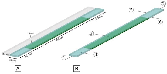
Figure 2.
Simulation domain with (A) main dimensions, (B) boundaries (1—inlet, 2—outlet, 3—upper wall, 4—lower wall, 5—plane of symmetry, 6—lateral wall).
Boundary conditions along the channel walls implement adiabatic constraints, with the exception of the bottom surface which maintains a constant temperature of . The thermal difference between inlet flow and heated wall surface is established at 23 K. Boundary conditions are summarized in Table 1. Considering the RANS modeling approach and the geometric characteristics of the flow domain, symmetry conditions are applied along the spanwise direction, enabling the computational analysis of half the domain.

Table 1.
Boundary conditions.
The designated topology optimization region (denoted in green in Figure 2) begins 220 mm downstream from the inlet and extends 840 mm along the channel length. This positioning preserves the remaining channel section from flow perturbations to mitigate potential reverse flow phenomena. The optimization region features a reduced height of 4 mm compared to the full channel height of 12 mm while spanning the entire width of 120 mm. These dimensional constraints have been specifically implemented to generate turbulator configurations within geometric parameters comparable to those previously investigated. In particular, extensive experimental results have already been acquired by the authors about standard V-shaped turbulators with the same height; thus, they allow direct comparative analysis between numerical and experimental data for this channel configuration. To give a first idea of the shape of the turbolators obtainable by TO, with respect to the more standard ones, Figure 3A shows the investigated domain with V-down turbulators while Figure 3B shows an example of the optimized obstacles, which will be more thoroughly described in the following sections.
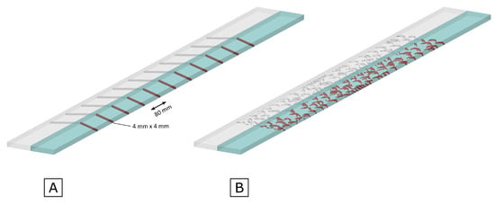
Figure 3.
Simulation domain with (A) standard V-down ribs, (B) ToffeeX turbulators.
2.3. Sensitivity Analysis Within ToffeeX
Initially, a sensitivity analysis has been performed within the software ToffeeX. Due to symmetry, half of a channel equipped with adiabatic V-down ribs (, apexes of the V pointing in the direction of flow) on the lower wall has been modeled on different meshes, respectively, of 400 k, 1 M, 2 M, 4 M, 8 M, and 16 M cells. The bulk outlet temperature and the pressure calculated at the inlet (which corresponds to the pressure difference along the whole channel) have been used as parameters for the mesh sensitivity analysis, showing that a 4 M cells mesh can be used without wasting computational resources and time, avoiding introducing a consistent error with respect to the value obtained for a finer mesh. The relative error e, computed by the following equations (Equations (4) and (5)), has been applied for the comparisons, and the obtained data are shown in Figure 4.
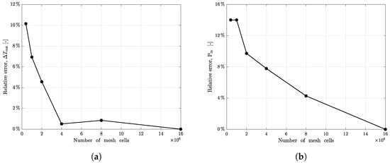
However, even the result deriving from a mesh with 400 k cells leads to a result that can give a good indication of the phenomenon and significantly shorten the computational times required, so it has been decided to work initially with a light mesh with 400 k cells and then to expand the TO procedure on a channel discretized with a finer mesh of D 4 M cells.
2.4. Validation of the CFD Model Inside ToffeeX
Before proceeding with TO, the CFD model applied by the optimization software has been benchmarked with respect to other previously validated CFD models and with available experimental data. The tested channels tested have the same boundary conditions, but adiabatic ribs are applied both on upper and lower walls, and parallel and in line; two types of ribbed channel configurations have been examined, denominated as V-down and V-up (the V-up configuration presents apexes oriented upstream relative to the flow direction). For both configurations, three different dimensionless pitch-to-side ratios have been analyzed; specifically, considering a 4 mm height rib, they have been placed equidistant from each other after 10, 20, and 40 times the height of the ribs. These configurations have been identified as P10S4, P20S4, and P40S4, respectively. More details on the geometric configuration, data, and results can be found in [46].
The analysis of the CFD model has been conducted at first by direct comparison of the outlet bulk temperature, since in the experimental setup is directly measured. It reveals that there are really close values between experimental and numerical data and between the Fluent and ToffeeX results. For the validation assessment, the thermal power exchanged has been selected as representative parameter. The heat transfer rate by the air flowing through the channel has been determined using the fundamental relation . This approach provides a more comprehensive validation metric for evaluating the accuracy of the overall thermal performance prediction of the computational model.
From Figure 5, it is evident that for each configuration, the CFD model employed by the TO software tends to underestimate both temperature and heat flux values. However, these deviations remain within acceptable error margins for the purpose of validating the CFD model. This validation assessment holds true both when the benchmark is against high-reliability Fluent simulations and when it is against experimental data collected in laboratory settings over the years for these specific configurations. The underestimation pattern across multiple configuration scenarios suggests a systematic behavior in the computational approach while maintaining sufficient accuracy for practical engineering applications. This validation framework provides confidence in the CFD model’s predictive capabilities despite its tendency toward conservative estimates of thermal parameters.
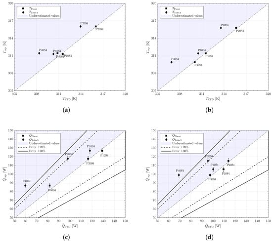
Figure 5.
An overview of the validation of the CFD model implemented in ToffeeX: (a) Outlet bulk temperature comparisons for V-down configuration. (b) Outlet bulk temperature comparisons for V-up configuration. (c) Heat transfer rate comparisons for V-down configuration. (d) Heat transfer rate comparisons for V-up configuration.
2.5. Design Setup
The computational design procedure is implemented by a bi-objective optimization framework that simultaneously targets thermal performance enhancement and hydraulic efficiency. The two objective functions are as follows: Maximize Heat Transfer and Minimize Total Pressure Losses, with the optimization governed by the weighted ratio between these competing objectives. Following the parametric evaluation of various weighting configurations, the optimization algorithm has been configured, in the end, with specific objective function coefficients: for heat transfer enhancement and for pressure loss minimization. This differential in weighting coefficients (5000:1) reflects the prioritization of thermal performance while substantially neglecting hydraulic penalties, in line with the objectives of the current investigation.
Spatial constraints have been imposed on the TO domain, restricting material distribution to the previously described subset of the channel geometry. Additionally, solid volumetric fraction constraints have been implemented to regulate material utilization within the design region. The range of 4% to 40% of solid volumetric fraction has been investigated. For the solid that will constitute the new turbulators, a fictitious material has been chosen, having a very low thermal conductivity ( W/m K) to mimic the properties of the standard polymethyl methacrylate turbulators tested in the experimental channel. This avoids the conductive fin effects.
Based on convergence analysis and computational resource optimization, the TO algorithm has been executed for 5000 iterations per configuration, which preliminary benchmarking determined sufficient to achieve solution convergence while maintaining computational efficiency.
2.6. CFD Model and Method with OpenFOAM
The ToffeeX results have been further validated by comparison with simulations performed with another CFD software tool. The Fluid solver of the OpenFOAM CFD software suite version 11 [52] has been selected. In particular, the best filling volume percentage has been selected as the optimum candidate and therefore subsequently analyzed in OpenFOAM through conventional RANS simulations on a high resolution mesh.
To grant a consistent comparison, all the settings of the domain and boundary conditions, and also the values of the fluid properties relevant for the thermo-fluid dynamics behavior, have been set equal to those used in the simulations performed with ToffeeX.
Again, as performed with ToffeeX, steady-state simulations have been carried out, monitoring both the convergence of the residuals (with threshold to stop the simulations set at ) and the stabilization of the quantities of interest (namely considering convergence reached when the variations become lower than K).
In order to create the mesh for the OpenFOAM simulations, the turbulator shapes returned by ToffeeX have been exported using the stereolitography (STL) format. Then, the mesh has been created, exploiting two utilities available in the standard OpenFOAM distributions: blockMesh has been used to build a preliminary background mesh, fully structured and suitable to be subsequently trimmed and adapted to follow the turbulators’ geometry using snappyHexMesh. The latter also allowed the automatic refinement of the background mesh in the regions around the turbulators, up to a distance of 1.75 mm from their external surfaces. Due to the complexity of the geometry, it has been decided to add no mesh boundary layers.
As already said, the final aim of the research is two-fold, with the creation of a methodological pipeline for heat transfer optimization that can be also applied in companies, in addition to the selection of the optimum shape of the turbulators. Thus, as is also the case in the OpenFOAM framework, RANS simulations have been favored to reduce the computational burden. The SST model has been identified as the best choice to capture the fluid dynamics and thermal interactions in the presence of complex geometries. The model coefficients have been left at the standard values.
Concerning the other simulation settings, first-order discretization schemes have been selected for the final simulations, again considering the first objective described in the previous lines. In fact, some preliminary simulations have been performed also with second-order schemes, leading to no change in the trends in the results and to small variations on the final , but with a much slower convergence due to more oscillating velocity fields.
Assessment of the Mesh Independence and Validation of the Simulations
Mesh resolution was varied to assess mesh independence: meshes from 2.14 M to 34.5 M cells were tested. For all resolutions, the mesh obtained with snappyHexMesh is still predominantly structured with hexahedral cells, with unstructured tetrahedral and polyhedral cells in the regions neighbouring the turbulators. For all resolutions, the background cell aspect ratio between the channel height direction and the streamwise and spanwise directions was kept to 0.62. The average mesh non-orthogonality was kept under 8% for all the meshes.
Figure 6 shows the 34.5 M cells mesh created with blockMesh and snappyHexMesh for the 8% filling volume percentage configuration. When using meshes between 4 M and 34.5 M cells, the difference in the remains under K.
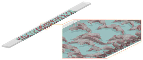
Figure 6.
Computational mesh (34.5 M cells) used for the OpenFOAM simulations.
To validate the numerical setup, a simulation has also been performed on the P20S4 V-down ribs test case, for which, as already said, both previous high-resolution simulations performed with Ansys Fluent 2023 R1 and accurate experimental results are available [46]. The values predicted by the OpenFOAM simulation are 114 W for the total heat transfer rate and 88.93 W/m2K for the convective heat transfer coefficient h, in good agreement with the previously determined values ( W and W/m2K [46]). With respect to the experimental values, errors are around 3% for the total heat transfer rate and 10% for the convective heat transfer coefficient computed from the energy balance ( W and W/m2K [46]).
3. Results and Discussion
When considering a constant wall temperature boundary condition, an effective preliminary approach to evaluate the heat transfer performance within the channel is to analyze the bulk temperature of the fluid at the outlet of the channel, . This parameter serves as a valuable indicator of the system’s thermal behavior. In particular, a higher difference between the inlet temperature, set at , and the outlet temperature, , under these boundary conditions corresponds to a more efficient heat transfer process. This is because a higher outlet temperature reflects a greater amount of thermal energy absorbed by the fluid as it flows through the channel, thereby indicating an enhanced heat transfer capability of the given configuration or design solution.
In order to establish a basis for comparison, a reference case consisting of a channel with the standard P20S4 V-down rib configuration has been selected (Figure 3A). Simulations have been conducted using both ToffeeX and OpenFOAM, with identical inlet temperature conditions. This reference case serves as a benchmark against which the heat transfer performance of other configurations can be evaluated.
Furthermore, to quantify the heat transfer efficiency as a percentage, the following ratio has been examined:
Subsequently, the results obtained from the most promising topology-optimized turbulators have been validated through simulations performed with OpenFOAM. This step has been useful to ensure the accuracy and reliability of the performance predictions for the selected configurations, providing a robust comparison with the numerical models and confirming the effectiveness of the optimized designs.
3.1. Topology Optimization
Solid volumetric fractions ranging from 4% to 40% have been tested to evaluate the effect of different filling levels on the heat transfer performance. Some examples of the generated turbulators at different filling volume percentages can be seen in Figure 7, whereas preliminary results from the analysis of the optimized design, based on an initial mesh, are shown in Figure 8.
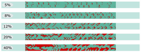
Figure 7.
ToffeeX turbulator geometries at different filling volume percentages, top view.
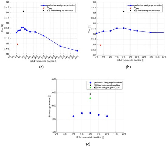
Figure 8.
Results on after topology optimization at different solid volumetric fractions: (a) Outlet bulk temperature distribution of the overall range tested. (b) Zoom in on the outlet bulk temperature distribution. (c) Percentage increase of the most promising configurations.
The results indicate that the optimal solid volumetric fraction lies within the range of 6% to 10%, with the outlet temperature showing a clear improvement within this interval. A more focused analysis, particularly between 7% and 9%, reveals the most significant improvements in thermal performance. In contrast, when the solid volumetric fraction exceeds 12%, the outlet temperature begins to decrease consistently, suggesting that higher filling fractions are detrimental to heat transfer efficiency.
Since differences within the range of 6–10% are negligible and are even more so within the range 7–9%, the 8% solid volumetric fraction has been chosen to perform an accurate topology optimization simulation. The results showed a notable increase in the outlet temperature. Specifically, the optimized design with this solid volumetric fraction led to a temperature increase of nearly 30% compared to a channel with standard V-down ribs, as depicted in Figure 8c. The resulting turbulators can be seen in details also in Figure 6. The proposed channel demonstrates significant potential for practical use due to its high compatibility with common industrial applications and manufacturing techniques.
3.2. OpenFOAM CFD Simulations
As hinted at in the previous sections, after validation, the numerical setup using OpenFOAM has been used to perform the final simulation with the turbulators at 8% filling volume percentage. The resulting bulk temperature is 316.97 K, with a percentage increase of 25.87% with respect to the reference V-down ribs case, as illustrated in Figure 8. This substantial enhancement further supports the validity of the proposed design strategy.
Moreover, in order to offer a qualitative insight into the thermal behavior induced by the presence of the turbulators, representative examples of the temperature distribution within the computational domain are presented.
Figure 9 and Figure 10 show the velocity fields on some vertical slices of the domain, at 1.5, 3 and 4.5 mm from the symmetry plane, for the ToffeeX 8% filling volume percentage case and for the P20S4 V-down ribs case, respectively.
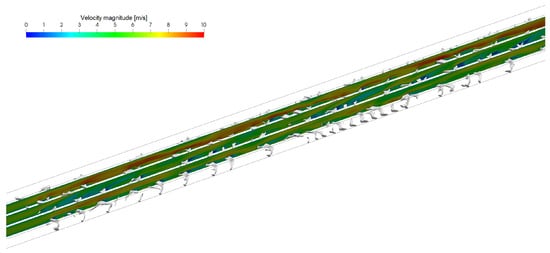
Figure 9.
Velocity fields on vertical slices of the domain at 1.5, 3, and 4.5 mm from the symmetry plane for the ToffeeX 8% filling volume percentage case.
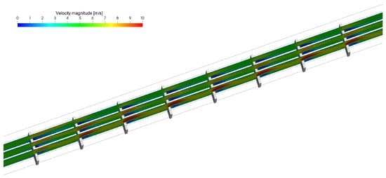
Figure 10.
Velocity fields on vertical slices of the domain at 1.5, 3, and 4.5 mm from the symmetry plane for the P20S4 V-down ribs case.
From these figures, it is evident that the velocity within the domain presents larger gradients and more frequent local variations when using the optimized geometry compared to traditional V-down ribs. In fact, as expected, the new obstacles manage to promote turbulence.
Figure 11 and Figure 12 show the velocity and temperature fields on a horizontal slice of the domain at a 1 mm height from the bottom boundary, for the ToffeeX 8% filling volume percentage case and for the P20S4 V-down ribs case, respectively.

Figure 11.
Velocity and temperature fields on a horizontal slice of the domain at 1 mm height from the bottom boundary for the ToffeeX 8% filling volume percentage case.

Figure 12.
Velocity and temperature fields on a horizontal slice of the domain at 1 mm height from the bottom boundary for the P20S4 V-down ribs case.
Looking at the figures, it is well established that the introduction of obstacles within a channel has a visible impact on the fluid dynamics and thermal field. The presence of such features induces the formation of recirculation zones and vortical structures immediately downstream, which alter the local temperature distribution. Such regions typically exhibit different temperature values compared to the surrounding flow, indicating that enhanced mixing occurs as a result of increased turbulence. The interaction between the main flow and the recirculating zones promotes a higher heat transfer. The ToffeeX-generated geometries exhibit more irregular and fragmented flow structures compared to the regular, periodic recirculation zones observed in the V-down ribs configuration. This effectively manages to increase the mixing of the fluid.
3.3. Concluding Remarks and Future Developments
The results obtained in this study underscore the potential of the newly designed turbulators to enhance thermal performance in industrial heat exchanger applications. ToffeeX facilitates this process by combining CFD simulations with advanced optimization algorithms. It enables the automated generation of innovative, application-specific geometries while incorporating geometric and manufacturing constraints directly into the design workflow. Therefore, the proposed approach may serve as a promising starting point for further investigations into geometry-based thermal optimization.
Nonetheless, there remains significant room for development, particularly in refining the topology optimization framework. In fact, in addition to exploring a wide ranges of flow conditions, one possible direction for future work involves increasing the resolution of the parametric study, for instance by considering more intermediate solid volume fractions between 5% and 10%, or by extending the analysis to even bigger areas of the domain. Such an approach could offer a more comprehensive understanding of the relationship between material distribution and heat transfer efficiency.
Alternatively, the optimization algorithm could be adapted to remove the constraint on the solid volumetric fraction altogether, enabling the generation of novel geometries without predefined constraints. In such cases, the most promising configurations identified through numerical simulation could also be selected for experimental validation, providing a more robust assessment of their practical applicability.
Additionally, despite the fact that the current work does not explicitly address manufacturability constraints such as minimum feature size, overhang angles, or support structures, these aspects are recognized as critical for practical implementation and will be considered in future developments of this research.
4. Conclusions
This work presents the development of novel turbulator geometries aimed at enhancing heat transfer in a high aspect ratio rectangular channel previously investigated by the authors. The designs have been generated through a TO process using a physics-driven design software and further evaluated through simulations performed in OpenFOAM. Several design alternatives have been explored by varying the solid volumetric fraction within the optimization domain. The results show that a solid volume fraction of approximately 8% yields the most effective configurations under the tested conditions. Compared to conventional V-down rib turbulators, the optimized geometries achieved a 25–30% increase in outlet fluid temperature, confirming their superior thermal performance under identical flow conditions. The study demonstrates the effectiveness of integrating topology optimization with CFD techniques to design high-performance surface features for heat exchangers.
Author Contributions
Conceptualization, M.C. and M.G.; methodology, M.C. and M.G.; software, M.C., R.C., and A.D.C.; validation, M.C., D.F., P.G., and L.V.; formal analysis, M.C., P.G., and M.G.; investigation, M.C., D.F., and P.G.; resources, M.C., R.C., A.D.C., D.F., P.G., L.V., and M.G.; data curation, M.C.; writing—original draft preparation, M.C. and A.D.C.; writing—review and editing, M.C., R.C., A.D.C., L.V., and M.G.; visualization, M.C. and R.C.; supervision, M.G.; funding acquisition, M.G. All authors have read and agreed to the published version of the manuscript.
Funding
The authors would like to acknowledge the following financial support: PNRR-M4C2-I1.1—MUR Call for proposals n.104 of 2 February 2022—PRIN 2022—ERC sector PE8—Project title: MOOD4HEX-MOrphology Optimized Design for Heat EXchangers—Project Code 2022SJP2A5-CUP Code D53D23004040006—Funded by the European Union—NextGenerationEU.
Data Availability Statement
The original contributions presented in this study are included in the article. Further inquiries can be directed to the corresponding author(s).
Acknowledgments
We would like to thank the late Alfonso Niro for his valuable guidance and inspiration throughout the development of this work.
Conflicts of Interest
Antonio Di Caterino is an employee of ToffeeX. The remaining authors declare that the research was conducted in the absence of any commercial or financial relationships that could be construed as a potential conflict of interest. The funders had no role in the design of this study; in the collection, analyses, or interpretation of the data; in the writing of this manuscript; or in the decision to publish the results.
Nomenclature
The following abbreviations are used in this manuscript:
| Latin letters | |
| a | Local impermeability [−]; |
| AM | Additive Manufacturing; |
| CFD | Computational Fluid Dynamics; |
| Specific heat capacity []; | |
| D | Thermal diffusivity []; |
| e | Relative error [−]; |
| f | Objective function [−]; |
| F | Multi-objective function [−]; |
| h | Convective heat transfer coefficient [W/m2K]; |
| Mass flow rate []; | |
| Nusselt number [−]; | |
| P | Fluid pressure [Pa]; |
| Prandtl number [−]; | |
| Heat transfer rate []; | |
| RANS | Reynolds-Averaged Navier–Stokes; |
| Reynolds number [−]; | |
| S | Solution of the optimization problem [−]; |
| T | Temperature [K]; |
| TO | Topology Optimization; |
| Fluid velocity []. | |
| Greek letters | |
| Angle between the ribs and the wall [°]; | |
| Thermal conductivity []; | |
| Dynamic viscosity [Pa s]; | |
| Kinematic viscosity []; | |
| Density []; | |
| Feasible solution [−]; | |
| Set of feasible solution [−]; | |
| Weight of the objective function [−]; | |
| Design domain [−]. | |
| Subscripts | |
| b | Bulk; |
| CFD | Numerical; |
| exp | Experimental; |
| HT | Heat transfer; |
| in | Inlet; |
| out | Outlet; |
| PL | Pressure loss; |
| t | Turbulent; |
| w | Wall. |
References
- Fawaz, A.; Hua, Y.; Le Corre, S.; Fan, Y.; Luo, L. Topology optimization of heat exchangers: A review. Energy 2022, 252, 124053. [Google Scholar] [CrossRef]
- Cerdá, J.; Cafaro, V.G.; Cafaro, D.C. Novel Mathematical Approaches for the Structural Synthesis of Heat Exchanger Networks. Ind. Eng. Chem. Res. 2022, 61, 464–486. [Google Scholar] [CrossRef]
- Yao, J. A Review of Industrial Heat Exchange Optimization. IOP Conf. Ser. Earth Environ. Sci. 2018, 108, 042036. [Google Scholar] [CrossRef]
- Ait Laasri, I.; Charai, M.; Mghazli, M.O.; Outzourhit, A. Energy performance assessment of a novel enhanced solar thermal system with topology optimized latent heat thermal energy storage unit for domestic water heating. Renew. Energy 2024, 224, 120189. [Google Scholar] [CrossRef]
- Sarap, M.; Kallaste, A.; Shams Ghahfarokhi, P.; Tiismus, H.; Vaimann, T. Utilization of additive manufacturing in the thermal design of electrical machines: A review. Machines 2022, 10, 251. [Google Scholar] [CrossRef]
- Anh, N.T.; Quynh, N.X.; Tung, T.T. Study on Topology Optimization Design for Additive Manufacturing. Eng. Technol. Appl. Sci. Res. 2024, 14, 14437–14441. [Google Scholar] [CrossRef]
- Anwajler, B. Potential of 3D Printing for Heat Exchanger Heat Transfer Optimization—Sustainability Perspective. Inventions 2024, 9, 60. [Google Scholar] [CrossRef]
- Li, N.; Hugo, J.M.; Serret, D.; Zhang, Y.; Gomes, S. A two-step parametric generative method for heat exchangers design in additive manufacturing. Procedia CIRP 2022, 109, 508–512. [Google Scholar] [CrossRef]
- Ghasemi, A.; Elham, A. Multi-objective topology optimization of pin-fin heat exchangers using spectral and finite-element methods. Struct. Multidiscip. Optim. 2021, 64, 2075–2095. [Google Scholar] [CrossRef]
- Pei, E.; Bernard, A.; Gu, D.; Klahn, C.; Monzón, M.; Petersen, M.; Sun, T. Springer Handbook of Additive Manufacturing; Springer Nature: Cham, Switzerland, 2023. [Google Scholar] [CrossRef]
- Careri, F.; Khan, R.H.; Todd, C.; Attallah, M.M. Additive manufacturing of heat exchangers in aerospace applications: A review. Appl. Therm. Eng. 2023, 235, 121387. [Google Scholar] [CrossRef]
- Liang, X.; Li, A.; Rollett, A.D.; Zhang, Y.J. An isogeometric analysis-based topology optimization framework for 2D cross-flow heat exchangers with manufacturability constraints. Eng. Comput. 2022, 38, 4829–4852. [Google Scholar] [CrossRef]
- Wei, L.s.; Liu, H.l.; Tang, C.g.; Tang, X.p.; Shao, X.d.; Xie, G. Investigation of novel type of cylindrical lithium-ion battery heat exchangers based on topology optimization. Energy 2024, 304, 131886. [Google Scholar] [CrossRef]
- Sun, S.; Rankouhi, B.; Thoma, D.J.; Cheadle, M.J.; Maples, G.D.; Anderson, M.H.; Nellis, G.; Qian, X. Topology optimization, additive manufacturing and thermohydraulic testing of heat sinks. Int. J. Heat Mass Transf. 2024, 224, 125281. [Google Scholar] [CrossRef]
- Dbouk, T. A review about the engineering design of optimal heat transfer systems using topology optimization. Appl. Therm. Eng. 2017, 112, 841–854. [Google Scholar] [CrossRef]
- Dong, C.C.; He, G.; Li, D.; Zhang, Z.; Cong, J.; Meng, Z. 3D Topology Optimization Design of Air Natural Convection Heat Transfer Fins. Nucl. Eng. Des. 2024, 429, 113623. [Google Scholar] [CrossRef]
- Paudel, B.J.; Masoomi, M.; Thompson, S.M. Multi-Objective Topology Optimization of Additively Manufactured Heat Exchangers. In Proceedings of the 2019 International Solid Freeform Fabrication Symposium, Austin, TX, USA, 12–14 August 2019. [Google Scholar] [CrossRef]
- Alexandersen, J.; Andreasen, C.S. A Review of Topology Optimisation for Fluid-Based Problems. Fluids 2020, 5, 29. [Google Scholar] [CrossRef]
- Shah, R.K.; Sekulic, D.P. Fundamentals of Heat Exchanger Design; John Wiley & Sons: Hoboken, NJ, USA, 2003. [Google Scholar] [CrossRef]
- Marler, R.T.; Arora, J.S. The weighted sum method for multi-objective optimization: New insights. Struct. Multidisc. Optim. 2010, 41, 853–862. [Google Scholar] [CrossRef]
- Caruana, R.; Marocco, L.; Guilizzoni, M. A novel CFD model for design and performance prediction of recuperators for Indirect Evaporative Cooling. Therm. Sci. Eng. Prog. 2024, 51, 102619. [Google Scholar] [CrossRef]
- Caruana, R.; Marocco, L.; De Antonellis, S.; Guilizzoni, M. Effect of the plates geometry on the performance of a cross-flow recuperator for indirect evaporative cooling systems. J. Phys. Conf. Ser. 2024, 2766, 012177. [Google Scholar] [CrossRef]
- Sahin, B.; Yakut, K.; Kotcioglu, I.; Celik, C. Optimum design parameters of a heat exchanger. Appl. Energy 2005, 82, 90–106. [Google Scholar] [CrossRef]
- Primo, T.; Calabrese, M.; Del Prete, A.; Anglani, A. Additive manufacturing integration with topology optimization methodology for innovative product design. Int. J. Adv. Manuf. Technol. 2017, 93, 467–479. [Google Scholar] [CrossRef]
- Lei, T.; Alexandersen, J.; Lazarov, B.S.; Wang, F.; Haertel, J.H.; De Angelis, S.; Sanna, S.; Sigmund, O.; Engelbrecht, K. Investment casting and experimental testing of heat sinks designed by topology optimization. Int. J. Heat Mass Transf. 2018, 127, 396–412. [Google Scholar] [CrossRef]
- Zeng, S.; Kanargi, B.; Lee, P.S. Experimental and numerical investigation of a mini channel forced air heat sink designed by topology optimization. Int. J. Heat Mass Transf. 2018, 121, 663–679. [Google Scholar] [CrossRef]
- Pietropaoli, M.; Montomoli, F.; Gaymann, A. Three-dimensional fluid topology optimization for heat transfer. Struct. Multidisc. Optim. 2019, 59, 801–812. [Google Scholar] [CrossRef]
- Jahan, S.; Wu, T.; Shin, Y.; Tovar, A.; El-Mounayri, H. Thermo-fluid topology optimization and experimental study of conformal cooling channels for 3D printed plastic injection molds. Procedia Manuf. 2019, 34, 631–639. [Google Scholar] [CrossRef]
- Li, H.; Ding, X.; Meng, F.; Jing, D.; Xiong, M. Optimal design and thermal modelling for liquid-cooled heat sink based on multi-objective topology optimization: An experimental and numerical study. Int. J. Heat Mass Transf. 2019, 144, 118638. [Google Scholar] [CrossRef]
- Yan, S.; Wang, F.; Hong, J.; Sigmund, O. Topology optimization of microchannel heat sinks using a two-layer model. Int. J. Heat Mass Transf. 2019, 143, 118462. [Google Scholar] [CrossRef]
- Hu, D.; Zhang, Z.; Li, Q. Numerical study on flow and heat transfer characteristics of microchannel designed using topological optimizations method. Sci. China Technol. Sci. 2020, 63, 105–115. [Google Scholar] [CrossRef]
- Høghøj, L.C.; Nørhave, D.R.; Alexandersen, J.; Sigmund, O.; Andreasen, C.S. Topology optimization of two fluid heat exchangers. Int. J. Heat Mass Transf. 2020, 163, 120543. [Google Scholar] [CrossRef]
- Ghosh, S.; Fernandez, E.; Kapat, J. Fluid-thermal topology optimization of gas turbine blade internal cooling ducts. J. Mech. Des. 2022, 144, 051703. [Google Scholar] [CrossRef]
- Ali, S.; Dbouk, T.; Wang, G.; Wang, D.; Drikakis, D. Advancing thermal performance through vortex generators morphing. Sci. Rep. 2023, 13, 368. [Google Scholar] [CrossRef] [PubMed]
- Hurry, A.S.; Hayward, K.; Guzzomi, F.; Rauthan, K.; Vafadar, A. Thermo-hydraulic performance evaluation of a NACA 63-015 heat exchanger with shark denticles as surface textures. Int. J. Heat Mass Transf. 2023, 216, 124591. [Google Scholar] [CrossRef]
- Xuan, W.; Xu, C.; Qian, C.; Wang, J.; Jiang, Z.; Ma, R.; Yu, B.; Shi, J.; Chen, J. Numerical simulation and thermodynamic test analysis of plate heat exchanger based on topology optimization. Appl. Therm. Eng. 2024, 255, 123882. [Google Scholar] [CrossRef]
- Navah, F.; Lamarche-Gagnon, M.É.; Ilinca, F. Thermofluid topology optimization for cooling channel design. Appl. Therm. Eng. 2024, 236, 121317. [Google Scholar] [CrossRef]
- Wang, D.; Wu, Q.; Wang, G.; Zhang, H.; Yuan, H. Experimental and numerical study of plate heat exchanger based on topology optimization. Int. J. Therm. Sci. 2024, 195, 108659. [Google Scholar] [CrossRef]
- Hu, J.; Chen, C.; Wang, X.; Xin, G.; Wang, M. Improvement of flow and heat transfer performance of microchannels with different ribs using topology optimization. Appl. Therm. Eng. 2024, 244, 122672. [Google Scholar] [CrossRef]
- Belwadi, Z.A.; Akula, R. Design of a PCM-based thermal management system for cylindrical Li-ion battery using topology optimization. Appl. Therm. Eng. 2025, 270, 126143. [Google Scholar] [CrossRef]
- Yang, C.; Wang, D.; Ali, S.; Wang, G.; Dbouk, T. Topology optimization of rectangular parallel plate heat exchanger unit. Int. J. Therm. Sci. 2025, 208, 109503. [Google Scholar] [CrossRef]
- Yu, H.; Li, T.; Zeng, X.; He, T.; Mao, N. A critical review on geometric improvements for heat transfer augmentation of microchannels. Energies 2022, 15, 9474. [Google Scholar] [CrossRef]
- Corti, M.; Gramazio, P.; Fustinoni, D.; Vitali, L.; Niro, A. Accuracy in evaluating heat transfer coefficient by RANS CFD simulations in a rectangular channel with high aspect ratio—Part 1: Benchmark on a channel with plane walls. J. Phys. Conf. Ser. 2023, 2509, 012009. [Google Scholar] [CrossRef]
- Corti, M.; Gramazio, P.; Fustinoni, D.; Vitali, L.; Niro, A. Accuracy in evaluating heat transfer coefficient by RANS CFD simulations in a rectangular channel with high aspect ratio—Part 2: Channel with ribbed walls. J. Phys. Conf. Ser. 2023, 2509, 012010. [Google Scholar] [CrossRef]
- Corti, M.; Gramazio, P.; Fustinoni, D.; Niro, A. Accuracy in evaluating convective heat transfer coefficient by RANS CFD simulations in a rectangular channel with high aspect ratio and 60° tilted staggered ribs. J. Phys. Conf. Ser. 2024, 2685, 012001. [Google Scholar] [CrossRef]
- Corti, M.; Gramazio, P.; Fustinoni, D.; Niro, A. Accuracy in evaluating convective heat transfer coefficient by RANS CFD simulations in a rectangular channel with high aspect ratio and V-shaped ribs. J. Phys. Conf. Ser. 2025, 2940, 012002. [Google Scholar] [CrossRef]
- Fustinoni, D.; Gramazio, P.; Colombo, L.P.; Niro, A. Heat Transfer Characteristics in Forced Convection Through a Rectangular Channel with V-Shaped Rib Roughened Surfaces. In Proceedings of the 15th International Heat Transfer Conference, Kyoto, Japan, 10–15 August 2014. [Google Scholar] [CrossRef]
- Physics-Driven Generative Design Software: ToffeeX. Available online: https://toffeex.com/ (accessed on 5 May 2025).
- Raikar, P.P.; Anand, N.; Pini, M.; De Servi, C. Concurrent optimization of multiple heat transfer surfaces using adjoint-based optimization with a CAD-based parametrization. Int. J. Heat Mass Transf. 2025, 236, 126230. [Google Scholar] [CrossRef]
- Kenway, G.K.; Mader, C.A.; He, P.; Martins, J.R. Effective adjoint approaches for computational fluid dynamics. Prog. Aerosp. Sci. 2019, 110, 100542. [Google Scholar] [CrossRef]
- Liu, Q.; Vasilyev, O.V. A Brinkman penalization method for compressible flows in complex geometries. J. Comput. Phys. 2007, 227, 946–966. [Google Scholar] [CrossRef]
- The OpenFOAM Foundation. OpenFOAM. Available online: https://openfoam.org/ (accessed on 5 May 2025).
Disclaimer/Publisher’s Note: The statements, opinions and data contained in all publications are solely those of the individual author(s) and contributor(s) and not of MDPI and/or the editor(s). MDPI and/or the editor(s) disclaim responsibility for any injury to people or property resulting from any ideas, methods, instructions or products referred to in the content. |
© 2025 by the authors. Licensee MDPI, Basel, Switzerland. This article is an open access article distributed under the terms and conditions of the Creative Commons Attribution (CC BY) license (https://creativecommons.org/licenses/by/4.0/).