Abstract
Characterizing the optimal operating parameters for a heat pump with a specific refrigerant is paramount, as it provides valuable guidance for refrigerant selection. The temperature mismatch between cold and hot fluids in the evaporator and condenser can lead to degraded thermal performance in heat pumps with large temperature variations. To address these two key issues, we selected several pure refrigerants with varying critical temperature levels for use in a large temperature variation heat pump configuration. The corresponding thermal performance was then investigated using the Ebsilon code under fixed temperature lift conditions as the operating temperature varied. It indicates that the maximum coefficient of performance (COP) is typically achieved when the deviation factors of temperature and pressure from their critical parameters fall within the ranges of 0.62~0.71 and 0.36~0.5, respectively. Our research recommends the binary refrigerant mixture of R152a/R1336mzz(z) (COP = 3.54) for the current operating conditions, as it significantly improves thermal performance compared to pure R1336mzz (z) (COP = 2.87) and R152a (COP = 3.01). Through research on the impact of the compositional ratio of R152a/R1336mzz(z) on the thermal performance of the heat pump, we found that that the optimal ratio of R1336mzz(z) component to R152a component is 0.5/0.5. This study offers valuable guidance for selecting the most suitable refrigerants for heat pumps in practical engineering design scenarios.
1. Introduction
Industry continues to rely on fossil fuels for its heat requirements [1,2], resulting in a surge in carbon emissions [3]. To contribute towards achieving carbon neutrality goals [4], industrial waste heat recovery utilizing heat pump technology [5,6,7,8] has garnered considerable attention from scholars. Traditional heat pumps employ pure refrigerant as their circulating fluid, maintaining a consistent temperature throughout both evaporation and condensation. However, this does not match with the variable temperature characteristics exhibited by industrial heat transfer media during the heat transfer processes [9]. Furthermore, due to constraints in critical temperature and pressure, the heat supply temperature of pure refrigerant heat pumps seldom exceeds 100 °C, making them unsuitable for fulfilling the high-grade heat demands of industrial settings [10,11].
The phase change process of non-azeotropic refrigerants [12,13] exhibits a unique property known as temperature glide, enabling them to match the temperature variations of the heat transfer medium and minimize heat transfer temperature differences [14,15]. This enhances the efficiency of heat pumps. Large temperature variable heat pumps (LTVHPs) utilizing non-azeotropic refrigerants are considered a crucial strategy for improving the energy efficiency of industrial processes and mitigating carbon emissions.
In contrast to pure refrigerants, numerous scholars have successfully blended various single refrigerants, leveraging their complementary advantages, to create mixed refrigerants [16,17]. This approach aims to achieve a lower condensing temperature and a higher coefficient of performance (COP) for heat pumps. Ganesan et al. [18] utilized MATLAB to establish a high-temperature heat pump (HTHP) model, specifically a two-stage cascade refrigeration system. This model employed natural non-azeotropic mixed refrigerants, such as R744/R600 and R744/R601, as the circulating fluids. The calculation results revealed that the system’s maximum heat production reached 205 kW, with a total COP reaching 4.5. This was achieved when the heat source temperature varied from 50 °C to 10 °C, and the hot water production temperature was maintained at 118 °C. Gomez-Hernandez et al. [19] employed a CO2/acetone mixture to substitute pure acetone as the circulating medium in a high-temperature heat pump (HTHP), aiming to enhance the system’s thermal performance. Their findings indicated that, with a mixture mass fraction of 0.05/0.95, a temperature rise of 70 K could be achieved between the heat source and radiator, resulting in a heating temperature of up to 200 °C. Notably, the corresponding COP increased by 46% compared to pure acetone. Hakkaki-Fard et al. [20] conducted an assessment of the efficacy of mixed refrigerant heat pumps for building heating in cold regions. Their analysis revealed that, when compared to R410A, a significant reduction in energy consumption of up to 12% could be achieved by utilizing R32/CO2 with a mass fraction of 0.8/0.2. Zhang et al. [21] explored the cycling potential of R152a/R245fa mixtures as a replacement for R234a. Experimental results indicated that the maximum condensation temperature on the radiator side reached 90 °C with a temperature lift of 45 °C. Notably, the corresponding COP of the heat pump exceeded 3.4, highlighting its superior efficiency. Zühlsdorf et al. [22] evaluated the performance of seven non-azeotropic refrigerants with varying compositions in a high-temperature heat pump operating at a heating temperature of 130 °C. The findings indicated that a mixture of propane and isopentane with a mass fraction of 0.5/0.5 achieved a COP of up to 3.08, whereas the COP of the heat pump using the corresponding pure fluid was only 2.89. Bamigbetan et al. [23] analyzed the cycling performance of a mixed refrigerant comprising n-pentane, n-butane, propane, and ammonia, operating under the conditions of a 40 °C evaporator inlet temperature and a condenser outlet temperature ranging from 90 °C to 150 °C. Their findings indicated that a mixture of n-pentane and n-butane, with a mass fraction of 0.6/0.4, exhibited the highest COP in the cascade heat pump system, surpassing that of a pure fluid by approximately 13%. Park et al. [24] conducted experimental measurements to gauge the potential of pure propylene, pure propane, and the mixture of dimethyl ether (DME) and R152a as replacements for R22 under typical heat pump conditions. The findings revealed that the thermal performance of the heat pump utilizing mixtures surpassed that of R22. The mixture of propylene, propane, and DME, with mass fractions of 0.45/0.40/0.15, exhibits the highest COP, equivalent to 5.7%.
Certain mixed refrigerants exhibit temperature glide, which refers to a temperature difference between the dew point and the bubble point exceeding 1 °C during the constant pressure phase transition. These refrigerants are classified as non-azeotropic refrigerants. Compared to pure refrigerants, the temperature glide of non-azeotropic refrigerants can effectively synchronize with the temperature variations of the heat transfer fluid during the heat exchange process, thus reducing exergy losses within the heat exchanger and enhancing the COP of the heat pump system [25]. Quenel et al. [26] conducted experimental measurements to assess the thermal performance of a heat pump system utilizing a propane/isobutane mixture as the refrigerant, under conditions of a 17 °C heat source temperature and a heat sink temperature ranging from 50 °C to 70 °C. Their findings revealed that the exergy losses in both the evaporator and condenser comprised approximately 21~25% of the total exergy losses within the system. Yelishala et al. [27] compared the thermal performance of a vapor compression refrigeration cycle employing a non-azeotropic hydrocarbon/CO2 mixture with that of a pure hydrocarbon refrigerant. This comparison was conducted under operating conditions where the heat transfer fluid in the condenser rose from 45 °C to 60 °C, and the heat transfer fluid in the evaporator declined from 30 °C to 15 °C. The results indicated that the COP of the hydrocarbon/CO2 system could be enhanced by 40% in comparison to the pure hydrocarbon system. Zühlsdorf et al. [28] analyzed the performance of a basic vapor compression heat pump employing 14 pure and non-azeotropic refrigerants. The study was performed under conditions analysis where the water temperature in the condenser was raised from 40 °C to 80 °C, and the inlet temperature of the heat source was maintained at 40 °C with a temperature decrease ranging from 5 °C to 20 °C. The results showed that an increase in the temperature change in heat source fluid leads to a greater mismatch between the two fluids (the heat source fluid and pure refrigerants) within the evaporator. This mismatch results in a lower COP compared to that achieved with mixed refrigerants. For example, when the heat source temperature declines by 10 °C, the optimal COP for pure refrigerants and non-azeotropic refrigerants is 5.28 and 5.62, respectively. Abedini et al. [29] suggested the use of various mixed refrigerants with varying temperature glides to attain the optimal COP based on three common heat transfer processes (latent heat/latent heat, latent heat/sensible heat, and sensible heat/sensible heat) encountered in industrial heat pump heat exchangers. As an instance, during the heating of liquid water in a heat sink from 140 °C to 200 °C under a constant pressure of 55 bar, the heat pump utilizing an ethanol/para-xylene refrigerant mixture (exhibiting a significant temperature glide of 26.8 °C) was able to attain a maximum COP of 3.60. Conversely, under the same operational conditions, the maximum COP achieved by a pure fluid (methanol) was only 3.25.
Different component ratios have a significant impact on the thermodynamic parameters, temperature glide of non-azeotropic refrigerants, as well as the thermodynamic performance of the heat pump system. Venkatarathnam and Srinivasa [30] discovered that the temperature glide results in a linear temperature–enthalpy relationship solely when binary non-azeotropic refrigerants are mixed in a 1:1 ratio. Any deviation from this 1:1 mixing ratio leads to a non-linear temperature–enthalpy relationship. Mulroy et al. [14] further demonstrated that the nonlinear nature of the temperature–enthalpy relationship in binary non-azeotropic refrigerants can be mitigated by the addition of a third component. Cheng et al. [31] established an air-source heat pump model to investigate the impact of varying the component ratio of the binary refrigerant R32/R1234ze(E) on the heat pump’s performance. Their findings revealed that as the proportion of R1234ze(E) increased from 0 to 1.0, the COP of the heat pump rose significantly by 70.3%, whereas the heat production decreased by 67.2%. On the other hand, D’Angelo et al. [32] discovered that the vapor injection heat pump system utilizing R290/R600a achieved its optimal COP when the mass fraction of R290 was set at 0.4. Guo et al. [33] evaluated the performance of a subcritical reheat high-temperature heat pump using five non-azeotropic refrigerants and discovered that the combination of n-hexane and propylene, with a molar fraction of 0.14/0.86, exhibited the highest COP, reaching 5.063. Tanaka et al. [34] conducted a study on the performance of a vapor compression cycle employing R1234ze(E)/R32 non-azeotropic refrigerants with varying mass ratios under the operating conditions of an evaporation temperature of −15 °C and a condensation temperature of 35 °C. Their findings indicated that the maximum COP was achieved when the mass fraction of R1234ze(E) was 0.89.
Changes in operating conditions significantly affect the performance of the heat pump cycle, generally exhibiting a trend where the COP diminishes as the temperature lifts [9]. Thu et al. [35] evaluated the performance of a domestic heat pump using a refrigerant mixture of HFC-32/HFO-1234yf/R744 with mass fractions of 0.22/0.72/0.06 across three distinct operating scenarios: summer cooling, winter heating, and winter high-temperature heating. Their results revealed that the peak COP was achieved in the winter heating mode, where the system’s exergy loss accounted for only 11–12% of the heat load.
In addition to the above theoretical analysis, numerous scholars have conducted experimental tests on the thermodynamic performance of non-azeotropic refrigerant heat pumps. The experimental results of Fleckl et al. [36] demonstrated that a simple single-stage heat pump using R1336mzz(Z) could achieve a COP ranging from 4.3 to 5.8 when operating under conditions of a 150 °C heating temperature and a 35 °C temperature lift. However, as the temperature lift of the heat pump rose to 70 °C, the COP plummeted significantly to only 2.5. Bobelin et al. [37] designed a high-temperature heat pump utilizing a mixture of refrigerants capable of generating high-quality heat at a temperature of 140 °C. The heat pump achieved a COP of 6 to 7 under operating conditions of a 55 °C heat source temperature and a 90 °C condensing temperature. Nevertheless, when the condensing temperature increased to 125 °C, the COP declined to a range of 2 to 3. Fukuda et al. [38] conducted an experimental study on the thermal performance of a single-stage, high-temperature, high-pressure heat pump using R1234ze(z). This heat pump was capable of producing 1.8 kW of heat under a temperature lift of 30 °C. Their results indicated that the COP under conditions of source/radiator temperatures of 45 °C/75 °C and 90 °C/120 °C were 5.4 and 6.6, respectively.
Current research primarily concentrates on analyzing the cycle performance of selected refrigerants under specific operating conditions, but it lacks illumination on the optimal operating parameters for a specific refrigerant and how to select the most suitable refrigerants for heat pumps in practical engineering design scenarios. In this study, we analyzed the thermodynamic parameters of eight distinct pure refrigerants across various critical temperature levels. Additionally, we investigated the thermal performance of the corresponding large temperature variation heat pump (LTVHP) with a constant temperature lift using Ebsilon software 16.0. We explored the universal correlation between the evaporation temperature and the thermal performance of the heat pump under a fixed temperature lift. This allowed us to establish a correlation between the optimal operating parameters and the unique thermodynamic characteristics of each pure refrigerant. Given the specific operating conditions in our study, we selected the most suitable binary refrigerant working pair. Furthermore, based on our research on temperature glide characteristics, we investigated the impact of the binary refrigerant ratio on the thermal performance of the LTVHP. The findings of this study could serve as a foundation for refrigerant selection in specific operating conditions.
2. Mathematical and Physical Models
2.1. High-Temperature Heat Pump Cycle
The ideal LTVHP configuration (illustrated in Figure 1) studied in this research comprises four fundamental thermodynamic processes: adiabatic compression in the compressor, isobaric heat rejection in the condenser, isenthalpic throttling through the throttle valve, and isobaric heat absorption in the evaporator. It is important to highlight that isobaric heat release in the condenser typically encompasses three thermodynamic processes: temperature drop of superheated gas, isothermal condensation of refrigerant, and temperature drop of supercooled gas. Due to the gas–liquid two-phase state at the throttle outlet, isobaric heat absorption typically involves two processes: isothermal evaporation and temperature rise of superheated gas. In this research, the term “large temperature variation” of the heat pump refers to three aspects: a significant temperature drop in the heat source fluid, a substantial temperature rise in the heat sink fluid, and a large temperature lift within the heat pump itself.
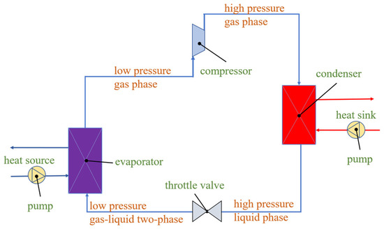
Figure 1.
System diagram of the heat pump.
2.2. Mathematical and Physical Models
2.2.1. Critical Equipment
The critical equipment in the LTVHP cycle primarily comprises the compressor, evaporator, condenser, and regenerator, and the corresponding energy conservation equations are detailed as follows.
- (1)
- Compressor
The compressor, a rotating device, elevates low-pressure gas to high-pressure gas, functioning as the central component of heat pump systems. The pressure ratio and isentropic efficiency [39] are crucial parameters that determine the compressor’s thermal efficiency. The equations pertaining to these parameters are expressed in Equations (1) and (2).
where denotes the pressure ratio; and represent the refrigerant pressure at the inlet and outlet of the compressor, respectively, which are generally specified by users.
where represents isentropic efficiency during the isentropic compression process in the compressor, and represent refrigerant enthalpy values at the inlet and outlet of the compressor, respectively; expresses enthalpy value under ideal conditions, which is determined by the inlet entropy of the compressor, , and the outlet pressure of the compressor, .
The electric energy [40] required to drive the compressor comprises both the enhancement of the refrigerant’s energy and mechanical energy losses. The formulation for this is expressed as follows:
where represents the electric energy; is the mechanical efficiency, which is set at 0.93; m is the mass flow rate of refrigerant passing through the compressor.
- (2)
- Throttle valve
The throttle valve is an isenthalpic device that regulates the refrigerant’s pressure by adjusting its flow velocity (through modification of the fluid’s flow area) in accordance with Bernoulli’s equation. Consequently, the fluid’s enthalpy at the outlet of the throttle valve is equivalent to that at its inlet. The fluid temperature at the outlet of the throttle valve is determined by the local thermodynamic parameters of pressure and enthalpy. The pressure of the throttle valve’s outlet is specified by the user, who selects an appropriate pressure based on the lower-end temperature difference of the evaporator, given its gas–liquid two-phase state.
- (3)
- Evaporator
The heat from the heat source (in this study, mid-temperature water) is conveyed into the heat pump cycle via the evaporator, positioned downstream of the throttle valve. The gas–liquid two-phase refrigerant exiting the throttle valve completely evaporates within the evaporator, subsequently undergoing further heating until it transitions into superheated gas. The energy conservation equation governing the exchange between the cold and hot fluids flowing through the evaporator is as follows [41]:
where represents the specific enthalpy of the refrigerant at the evaporator inlet, where the refrigerant is in a gas–liquid two-phase state. denotes the specific enthalpy of the refrigerant at the evaporator outlet, where the refrigerant is in the form of overheated gas. is equivalent to the saturation gas enthalpy, , plus the sensible heat absorption () resulting from superheating. Here, represents the specific heat at constant pressure of the refrigerant, and signifies the degree of superheating. and are the water temperatures at the evaporator inlet and outlet, respectively. is the specific heat of water at constant pressure. and refer to the mass flow rates of the refrigerant and water (the heat source fluid), respectively.
- (4)
- Condenser
The condenser, positioned subsequently to the compressor, is where the high-temperature refrigerant exiting the compressor releases its heat and undergoes a transformation into a low-temperature refrigerant. The heat release process typically comprises three stages: the temperature reduction of the superheated refrigerant, the condensation heat release of the saturated refrigerant, and the further temperature drop of the supercooled refrigerant. It is noteworthy that during the condensation process of binary refrigerants, a temperature glide phenomenon occurs characterized by a gradual decline in temperature as the gas content diminishes. The energy conservation equation governing the exchange between the cold and hot fluids flowing through the condenser is as follows [41]:
where and represent the water temperatures at the inlet and outlet of the condenser, respectively. is the specific heat of water at constant pressure. and are the mass flow rates of the refrigerant and water (the heat sink fluid), respectively. and are the specific enthalpies of the refrigerant at the inlet and outlet of the condenser, respectively. The refrigerant entering the condenser is in the form of superheated gas, and is the sum of the saturation gas enthalpy, , and the sensible heat absorption, , as stated in Equation (5), due to its superheat degree. The refrigerant exiting the condenser is in the form of supercooled gas, and is the difference between the saturation liquid enthalpy, , and the sensible heat release, , as defined in Equation (7), due to its supercool degree.
2.2.2. Comprehensive Evaluation Indicators of LTVHP
The overall thermal efficiency of a heat pump operating under large temperature variations is assessed using three thermodynamic indicators: COP (coefficient of performance), Qm (the heat output of the condenser per unit mass flow rate of refrigerant), and QV (the heat output of the condenser per unit volume flow rate of refrigerant).
COP, a widely adopted indicator for assessing the thermal efficiency of a heat pump, is defined as the ratio of the heat output delivered by the condenser to the input work demanded by the compressor [13,42].
where represents the heat transfer capacity of the condenser, and signifies the mechanical energy supplied to the compressor via the motor.
As the numerator of COP, the heat output of the condenser per unit mass flow rate (Qm, defined in Equation (9)) plays a direct role in determining the system’s thermal efficiency and the necessary refrigerant filling volume. Furthermore, the heat output of the condenser per unit volume flow rate of refrigerant (Qv, defined in Equation (10)) is equivalent to Qm divided by the refrigerant density at the compressor outlet. This factor is crucial in determining the geometric specifications of the equipment and system, ultimately affecting the engineering investment.
where m represents the mass flow rate of refrigerant, while V corresponds to the volume flow rate of refrigerant.
2.3. Computational Simulation
2.3.1. Computational Process
By thoroughly integrating the fundamental theory of energy conversion, mass transfer, and heat transfer, a calculation procedure has been developed and is depicted in Figure 2. The steps involved in this calculation are outlined as follows:
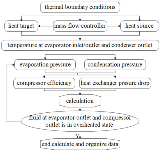
Figure 2.
Calculation flow chart.
- (1)
- Two mass flow controllers are configured for the fluids of the heat source and heat sink to maintain a constant outlet temperature.
- (2)
- Based on the heat demand of users and the energy quality of the heat source (including the type of heat source, as well as thermodynamic parameters of the fluid like mass flow rate, temperature, and pressure), the temperature of the refrigerant at the evaporator inlet/outlet and condenser outlet is determined.
- (3)
- Taking into account the superheat of the refrigerant at the evaporator outlet and the subcooling at the condenser outlet, the evaporation and condensation pressures are established.
- (4)
- The thermodynamic parameters of the heat pump are calculated in a coupled manner, after setting the isentropic efficiency of the compressor and the pressure drop across the heat exchangers.
- (5)
- It is assessed whether the thermodynamic parameters satisfy the following conditions: the refrigerant at both the evaporator outlet and compressor outlet should be in a superheated state (with a vapor quality of refrigerant equal to 1).
- (6)
- If the conditions mentioned in Step 5 are not met, the pressure of the refrigerant at the evaporator inlet is reduced, and the entire thermodynamic system is recalculated.
- (7)
- Finally, the thermodynamic parameters at the inlet and outlet of each component are output, and the internal change patterns are analyzed as the system undergoes disturbances.
2.3.2. Boundary Conditions and Assumptions
Based on the previously mentioned calculation requirements, the following conditions and assumptions have been established:
- (1)
- The fixed isentropic efficiency of the compressor is fixed at 0.85, while the mechanical efficiency is assigned at 0.93.
- (2)
- A temperature decrement of 20 °C is imposed on the heat source, aimed at maximizing the utilization of waste heat.
- (3)
- The evaporator’s lower-end temperature difference is set at 3 °C, and its upper-end temperature difference is determined to be 5 °C. This is achieved by adjusting the mass flow rate of the heat source fluid.
- (4)
- A lower-end temperature difference of 5 °C is assigned to the condenser.
- (5)
- The temperature increase of the heat sink is adjusted to 20 °C, matching the temperature variation of the heat source.
- (6)
- The pressure drops of the refrigerant flowing through the evaporator and condenser are specified as 0.05 bar and 0.2 bar, respectively.
- (7)
- It is assumed that the binary refrigerant is uniformly mixed.
- (8)
- Heat dissipation from both the evaporator and condenser to the surrounding environment is disregarded.
- (9)
- The evaluation of the heat pump cycle’s performance will be based on the constant reference thermodynamic parameters of the refrigerant, specifically 0 °C and 1 bar.
- (10)
- The minimal value for the pinch point is designated to be not less than 0.1 °C.
The Ebsilon software version 16.0 is utilized for calculating the current thermodynamic systems pertaining to LTVHP. This software is a professional code developed by the STEAG Power Group in Germany. As a visual thermal system modeling tool, it has gained widespread application in the design, optimization, transformation, and operational processes of diverse thermal systems. During the design phase, numerous scholars have employed this software to devise and refine thermodynamic configurations and parameters. It has furthermore been extensively utilized to analyze the variations in thermodynamic parameters under varying conditions, such as in traditional coal-fired power plants [43], solar thermal power generation [44], absorption heat pumps [45], combined heat and power generation [46,47], and gas–steam combined turbine systems [48]. During the system’s operational phase, this software can be employed to evaluate the equipment/system’s operational efficiency, detect system malfunctions, and design and evaluate transformation schemes. Numerous scientific studies and engineering practices have demonstrated that the Ebsilon software serves as a powerful tool for predicting the parameters and performance of thermal systems.
3. Results and Discussions
3.1. Thermodynamic Performance of LTVHP with Pure Refrigerant under Fixed Heat Source and Heat Sink
In this section, the configurations involving pure refrigerant are established within the constraints imposed by a fixed heat source and heat sink. Specifically, the heat source (such as waste heat from the power plant) maintains a temperature of 70 °C at the evaporator inlet and 50 °C at the outlet. Similarly, the heat sink (used in processes such as polymer preheating and food drying) maintains a temperature of 80 °C at the condenser inlet and 100 °C at the outlet.
To ensure an optimal alignment with the energy quality of the heat source, and to maximize the potential of the LTVHP system, the inlet and outlet temperatures of the refrigerant flowing through the evaporator are set at 47 °C and 65 °C, respectively. This ensures a 3 °C lower end temperature difference and a 5 °C upper end temperature difference for the evaporator. Notably, the evaporating pressure corresponds to the saturated pressure at the refrigerant temperature at the evaporator inlet, resulting in a superheated degree of 18 °C (65~47 °C) for the refrigerant at the evaporator outlet, which is a crucial thermodynamic parameter.
To ensure optimal alignment with the energy quality of the heat sink, the refrigerant temperature at the condenser outlet is set to 103 °C, maintaining a subcooling degree of 5 °C. It is crucial to note that the refrigerant temperature at the condenser outlet must exceed the outlet temperature of the condenser’s cooling fluid (also water in this study) to prevent temperature pinch points in the condenser. This is due to the isothermal nature of the refrigerant’s condensation process. Furthermore, the refrigerant temperature at the condenser inlet is determined by the compression process of the upstream compressor, where its outlet pressure corresponds to the saturated pressure at 108 °C.
Critical temperature and pressure are pivotal factors in assessing the suitability of a refrigerant and the thermal performance of the corresponding LTVHP. In this study, the refrigerant’s critical temperature must exceed the condensation temperature of 108 °C to guarantee complete condensation within the condenser.
Given these restrictions regarding the critical temperature, we have chosen several commonly used pure refrigerants from the past few years, categorized into four distinct types: HCFC, HFO, HCFO, and HFC. The environmental performance of these refrigerants is summarized in Table 1.

Table 1.
Environmental performance of pure refrigerants for LTVHP.
Table 2 presents the critical temperature (tcrit), critical pressure (pcrit), and bubble point temperature (tbub) at a pressure of 1 bar for the selected pure refrigerants. These refrigerants have been categorized into four levels based on the difference between their critical temperature and the condensation temperature (108 °C) in the condenser of the current models: low-temperature (L), medium-temperature (M), high-temperature (H), and very high-temperature (vH). As evident from the data in Table 2, the bubble point temperature at 1 bar exhibits a generally positive correlation with the critical temperature. The ratios, ε, of tbub to tcrit fall within the range of 0.6 to 0.7, respectively. However, no direct correlation between critical pressure and critical temperature is noticeable.

Table 2.
Thermodynamic parameters of pure refrigerants for LTVHP.
The thermodynamic performance of LTVHP with different pure refrigerants, listed in Table 2, has been calculated. Their COP, Qm, and QV values are illustrated in Figure 3. The refrigerants on the horizontal axis are arranged in ascending order based on their critical temperatures. From a broader perspective, the COP of LTVHP with R1234ze(e) (featuring a low critical temperature) is the lowest. The COP of LTVHP with R152a and R124 (possessing mid-range critical temperatures) is higher than that with R1234ze(e). Furthermore, the COP of LTVHP with other refrigerants (possessing high or very high critical temperatures) is relatively high. However, considering LTVHP with refrigerants in the H and vH critical temperature ranges, the COP does not strictly correlate monotonically with the critical temperature. This suggests the existence of optimal operating parameters for LTVHP with specific refrigerants.
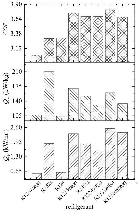
Figure 3.
Thermodynamic performance of LTVHP with pure refrigerants.
Qm and QV of LTVHP using R1234ze(e) and R124 reach their minimum values, with the former being a low-critical temperature refrigerant and the latter a medium-critical temperature refrigerant. However, there is an exception in the case of R152a, a medium-critical temperature refrigerant. In particular, its Qm value is even higher than that of LTVHP using pure refrigerants with high or very high critical temperatures, reaching a maximum of 210.27 kW/kg. When comparing the Qm and QV values of LTVHP with R1234ze(e) to those of R245fa and R1233zd(e) (which have comparable critical pressures to R1234ze(e)), it becomes evident that the critical temperature not only directly determines the COP but also significantly impacts Qm and QV. Furthermore, a comparison between R1233zd(e) and R1336mzz(Z) reveals that high critical pressure can also positively influence COP, Qm, and QV to some extent.
Qm and QV do not always vary in tandem with the refrigerant. For instance, when R152a is chosen as the refrigerant for LTVHP, Qm attains its maximum value, while the corresponding QV is not the maximum due to the influence of density (specifically, at the compressor outlet).
Figure 4 illustrates the low-pressure (pL), high-pressure (pH), and pressure ratio (αp) of LTVHP using various pure refrigerants. In this figure, pL and pH signify the evaporation and condensation pressures, respectively. It is evident from Figure 4 that the low pressure of LTVHP using R124, R1234ze(e), and R152a is comparatively elevated compared to the other refrigerants, and accordingly, the high pressure is similarly elevated. This is because the critical pressure of these three refrigerants is relatively high within the current calculation scope, while their corresponding critical temperatures are comparatively lower. Nonetheless, the pressure ratio of these three refrigerants is relatively small, which results in a low COP, as illustrated in Figure 3 and Figure 5. The evaporating and condensing pressure of LTVHP using R1336mzz(z) are the lowest, and its corresponding pressure ratio is the highest.
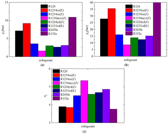
Figure 4.
Low pressure, high pressure, and pressure ratio of LTVHP with different pure refrigerants: (a) low pressure, (b) high pressure, (c) pressure ratio.
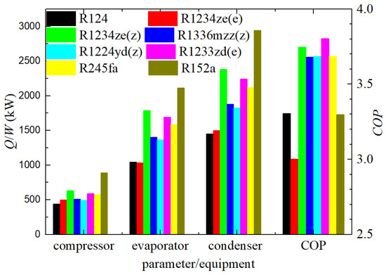
Figure 5.
Energy transfer or conversion of each equipment.
The thermal exchange from the heat source to the refrigerant in the evaporator, the heat transferred from the refrigerant to the heat sink in the condenser, and the heat converted from mechanical energy into the internal energy of the refrigerant in the compressor are depicted in Figure 5 for LTVHP using various pure refrigerants. In this section, the mass flow rate of the refrigerant remains consistent at a value of 14 kg/s across all scenarios. The heat transferred or converted per unit mass for LTVHP with R152a, R1234ze(e), R1233ze(e), and R245fa is relatively high. However, this does not correspond directly to the variation in the COP. The high heat output from LTVHP is attributed to the relatively high mechanical energy and heat energy inputs via the compressor and evaporator. Consequently, considering the total heating capacity, R152a, R1234ze(e), R1233ze(e), and R245fa are relatively preferred refrigerants. Nevertheless, this does not necessarily mean that their corresponding COPs are also relatively high, as exemplified by R152a, which has a COP of only 3.30. Upon analyzing the data presented in Figure 3, it becomes apparent that achieving all three qualities of environmental friendliness, high efficiency, and compactness simultaneously is not feasible.
To gain further insights into the underlying reasons for the thermodynamic performance variations observed in LTVHP, Figure 6 and Figure 7 present the t-s diagrams for LTVHP configurations employing various pure refrigerants. Segments 1–2 represent the heat release process in the condenser, which comprises three distinct sections: the superheated region, the saturated region, and the supercooled region. Segments 2–3 depict the isentropic throttling process carried out by the throttle valve. Segments 3–4 illustrate the endothermic process in the evaporator, encompassing both the saturated region and the superheated region. Finally, segments 4–1 represent the compression process, resulting in the production of high-temperature and high-pressure superheated gas.
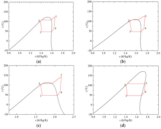
Figure 6.
t-s Diagrams of LTVHP configurations: (a) R124, (b) R1234ze(e), (c) 152a, (d) R1336mzz(z).
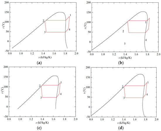
Figure 7.
t-s diagrams of LTVHP configurations: (a) R1234ze(z), (b) R245fa, (c) R1224yd(z), (d) R1233zd(e).
Figure 6a–c depict the t-s diagrams of LTVHP configurations utilizing R124, R1234ze(e), and R152, all exhibiting comparatively narrower diagrams in contrast to the other t-s diagrams shown in Figure 6 and Figure 7. It is observed that the two nearly vertical lines representing the compression process and the throttling process, are virtually indistinguishable from those seen in other t-s diagrams. This similarity arises from the assumption of a constant isentropic efficiency of 0.85 for the compressor across all configurations with different pure refrigerants, as well as the isenthalpic nature of the throttling process achieved by the throttle valve. Notably, these three t-s diagrams significantly diverge from the idealized Carnot cycle, given the fixed evaporation and condensation temperatures, resulting in inferior thermodynamic performance, as demonstrated in Figure 3 and Figure 5.
Figure 6d showcases the t-s diagrams of LTVHP configurations that employ R1336mzz(z), a refrigerant boasting the highest critical temperature. Remarkably, the operating range of this refrigerant is the farthest from its critical point. Consequently, the refrigerant temperature at the compressor outlet is merely 113.43 °C, translating to a superheat degree of just 5.43 °C. This significant factor has a considerable impact on heat release and the cycle’s COP, which stands at 3.68. Therefore, it becomes evident that as the refrigerant’s operating range moves further away from the critical point, the thermodynamic performance does not necessarily enhance.
Figure 7a–d illustrate the t-s diagrams of LTVHP configurations using R1234ze(z), R245fa, R1224yd(z), and R1233zd(e), none of which are positioned either too close or too far from their respective critical points. The COP for configurations with R1234ze(z), R245fa, and R1224yd(z) are comparable, averaging approximately 3.70. However, the COP for configurations utilizing R1233zd(e) is slightly higher, reaching 3.80. Given the fixed evaporation and condensation temperatures, the descending order of COP is as follows: R1233zd(e), followed by R1234ze(z), R245fa, and R1224yd(z), with the latter two exhibiting identical performance. These subtle differences in COP can be attributed to variations in critical parameters and other thermophysical properties. Overall, it can be inferred that the optimal COP is achieved when the distance between the condensation temperature and the critical temperature is neither excessively close nor overly distant from the critical point.
3.2. Thermodynamic Performance of LTVHP Utilizing Pure Refrigerant under Diverse Heat Source and Heat Sink Conditions
The calculation results in Section 3.1 point to the existence of an optimal operating range for a given pure refrigerant. In this section, we have designed a series of LTVHP configurations with a constant temperature lift for more application areas, where both the evaporating temperature (or evaporating pressure) and condensing temperature (or condensing pressure) vary concurrently by a fixed temperature increment. Subsequently, we have calculated the corresponding thermodynamic parameters of each node as well as the thermal performance of the entire LTVHP cycle.
Figure 8 illustrates the thermodynamic performance parameters, including ,, COP, and αp, of LTVHP as the evaporation temperature varies within the range of 7 to 77 °C, with a fixed step size of 10 °C. Simultaneously, the condensing temperature rises in lockstep with the evaporating temperature, maintaining a constant temperature lift of 61 °C, representing the difference between the condensing and evaporating temperatures. It is apparent from the figures that there is a gap in the data for certain LTVHP configurations using specific refrigerants (such as R124, R1234ze(e), and R152a). This missing segment corresponds precisely to the three narrow LTVHP t-s diagrams presented in Figure 6a–c. For R1234ze(e) and R152a, the lower limit of the condensation temperature is 108 °C (with a corresponding evaporating temperature of 47 °C), while for R124, it is 118 °C (with a corresponding evaporating temperature of 57 °C). This constraint arises from the requirement of refrigerant thermophysical properties that the condensation temperature must remain below the critical temperature, as detailed in Table 2.
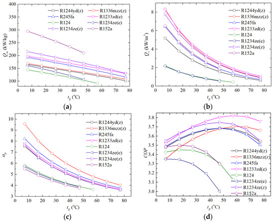
Figure 8.
Thermal performance of LTVHP with a series of heat sources with different energy quality, (a) , (b) , (c) αp, (d) COP.
As the evaporation temperature escalates, all thermodynamic parameters including , , and αp, diminish. The variations in for the evaporating temperature are relatively stable, and the corresponding change gradients are fairly similar across LTVHPs using different refrigerants. For refrigerants such as R1234ze(z), R1336mzz(z), R1224yd(z), R1233zd(e), and R245fa, the maximum relative changes of at an evaporating temperature of 77 °C compared to that at 7 °C range from 34% to 40%. The changes in LTVHPs using R245fa and R1234ze(z) are relatively significant, with relative changes of 39.61% and 39.31%, respectively, for operation at 77 °C versus 7 °C. For R124, R1234ze(e), and R152a, the relative variations lie within the range of 29% to 36%.
However, the changes in and αp are relatively pronounced. The maximum relative changes of in the condenser and αp flowing through the compressor in LTVHP with R1234ze(z), R1336mzz(z), R1224yd(z), R1233zd(e), and R245fa at 77 °C are in the ranges of 87~89% and 52~58%, respectively, compared to those at 7 °C. Additionally, the relative changes of and αp for R124, R1234ze(e), and R152a lie within the ranges of 71~81% and 32~37%, respectively. The decay rate of is significantly greater than that of , as the density increases with a larger magnitude relative to as the refrigerant’s pressure rises. Figure 9 demonstrates the variations in saturation pressure of the aforementioned pure refrigerants for temperature, where saturation pressure steadily increases with a gradually increasing slope as the temperature rises. However, the pressure ratio of LTVHP gradually diminishes with an increasing evaporating pressure due to the increasing baseline pressure.
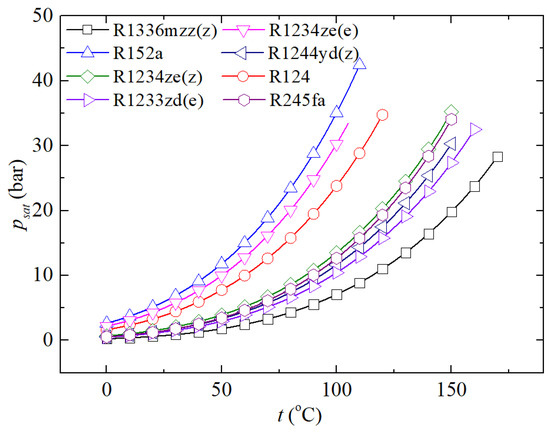
Figure 9.
Saturation pressure varies for temperature.
The COP of LTVHP initially surges and subsequently wanes with varying evaporating temperatures for all refrigerants. The evaporating temperature that corresponds to the peak COP value varies among distinct refrigerants. Under conditions of low evaporating temperature, where LTVHP typically operates, refrigerants such as R1234ze(z), R1233zd(e), R245fa, and R1244yd(z) exhibit comparatively superior performance. However, as the evaporating temperature rises, the benefits of refrigerants like R1233zd(e) and R1336mzz(z) gradually become evident due to their comparatively higher critical temperatures. In contrast, the performance of LTVHP with refrigerants R124, R1234ze(e), and R152a remains comparatively poor throughout the current operating temperature range.
Observing the curves in Figure 8d and the data listed in Table 2, it becomes apparent that the optimal operating points for different refrigerants exhibit a strong correlation with their critical temperature. Table 3 listed several typical thermodynamic parameters of LTVHP utilizing various refrigerants under their optimal design conditions, including the evaporating temperature (teva), condensing temperature (tcon), condenser outlet temperature (tcon,o), condensing pressure (pcon), critical pressure (pcrit), and critical temperature (tcrit). Using these fundamental physical parameters and thermodynamic cycle parameters, the degree of deviation from the critical point in the optimal configuration is quantified by the temperature deviation factor (δt) and pressure deviation factor (δp). δt is defined as the ratio of the condensing temperature to the critical temperature, while δp represents the ratio of the condensing pressure to the critical pressure. From the calculation results, we can deduce that the maximum COP for LTVHP is typically achieved when δt and δp are confined to the ranges of 0.62 to 0.71 and 0.36 to 0.5, respectively.

Table 3.
Thermodynamic parameters of LTVHP under optimal design conditions.
Figure 10 illustrates the progression of t-s diagrams for diverse LTVHP configurations as the evaporating temperature incrementally rises from 7 °C to 77 °C. The optimal operating scenarios are indicated with thick lines. Given the fixed temperature lift condition (predefined), the thermodynamic parameters of various points throughout the entire LTVHP cycle shift vertically as the evaporating temperature varies. Operating deviating from the critical point means less heat is absorbed from the heat source, which is not conducive to enhancing the COP. Conversely, operating too close to the critical point results in a lower achievement level in the Reversed Carnot Cycle, which is also not beneficial for improving the COP. Therefore, for an LTVHP utilizing a specific refrigerant, there must be optimal operating parameters within its standard operating range.
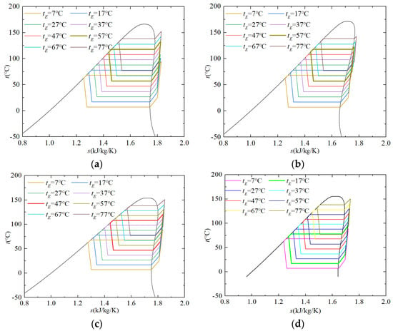
Figure 10.
t-s diagrams of LTVHP configurations utilizing a range of heat sources with different energy quality: (a) 1233zd(e), (b) R1336mzz(z), (c) R245fa, (d) R1224yd(z).
3.3. Thermodynamic Performance of Heat Pump with Binary Mixture
Due to isothermal condensation and evaporation, the temperature difference between cold and hot fluids in the evaporator and condenser of LTVHPs employing pure refrigerants such as R1336mzz(z) displays an extremely uneven distribution, as depicted in Figure 11. To ensure the normal operation of the evaporator, a unilateral phase change heat exchanger, the upper and lower end temperatures (UDT and LDT) are designated as 5 °C and 3 °C, respectively, by adjusting the mass flow rate of the heat source fluid. The curves indicate that the temperature difference throughout the heat exchange process is greater than that at the extremities, with a maximum difference reaching 20 °C. There is a point along the flow where the temperature difference between the hot and cold fluids is the smallest, located near the hot-fluid inlet position, under the condition of a predefined lower temperature difference. The minimum value for the pinch-point temperature differential is set at 3 °C for the condenser model. The significant heat transfer temperature difference between the cold and hot fluids in the condenser and evaporator leads to substantial exergy loss, thereby reducing the thermal and exergy efficiencies of the LTVHP cycle.
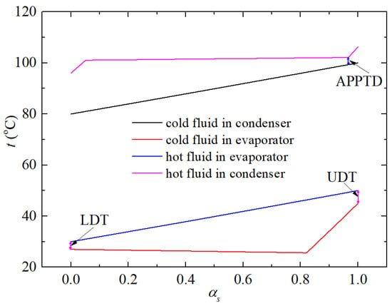
Figure 11.
Temperature distribution of cold and hot fluids flowing along their flow path in evaporator and condenser of LTVHP with R1336mzz(z).
To address the aforementioned problem, the binary refrigerant mixture is utilized to establish an LTVHP configuration, exemplified by R1336mzz(z) 0.5/R152a 0.5 as depicted in Figure 12. As the gas content ratio increases, the saturation temperature of the binary refrigerant rises during the phase transition process. Observing the schematic diagram comparing the temperature evolution of cold and hot fluids in the condenser and evaporator (where the cold fluid in the condenser is the binary refrigerant, and the hot fluid in the evaporator is also the binary refrigerant), it becomes evident that an outstanding temperature match between the hot and cold fluids is achieved, leading to a uniform temperature difference along the flow path.
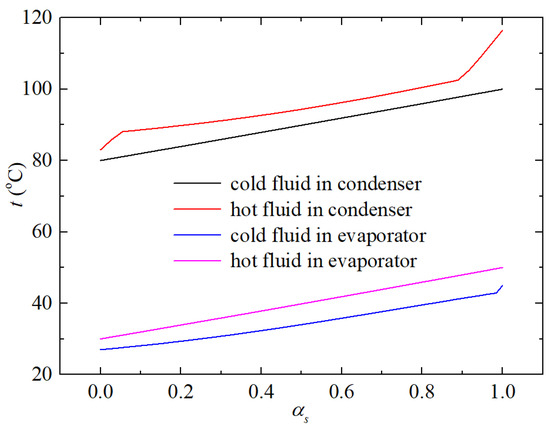
Figure 12.
Temperature distribution of cold and hot fluids flowing along their flow path in evaporator and condenser of LTVHP with R1336mzz(z)/R152a (0.5/0.5).
Given its relatively high critical temperature of 171.35 °C and its relatively low critical pressure of 29.03 bar, R1336mzz(z) is chosen as the primary component of the binary refrigerant. In this section, the energy quality of the heat source and heat sink is fixed at 30 °C/50 °C water (at evaporator inlet and outlet), and 80 °C water/100 °C steam (at condenser inlet and outlet), respectively. Additionally, a pinch point temperature difference of 3 °C is set for the condenser model. Consequently, the refrigerant temperature at the condenser outlet may vary for different refrigerants, considering the specific heat and latent heat variations among them. Operating an LTVHP with the aforementioned 30 °C heat source results in conditions far from the critical point of R1336mzz(z), leading to suboptimal performance. Therefore, several refrigerants with comparatively low critical temperatures, such as R227ea, R134a, R152a, and 1234ze(e), are selected as potential second components for the binary refrigerant. This selection aims to reduce the critical temperature level of the binary refrigerant compared to pure R1336mzz(z), thereby enhancing the COP of the corresponding LTVHP configuration. Table 4 lists the thermodynamic parameters of the binary refrigerant, assuming a component proportion of 0.5/0.5 with R1336mzz(z) as the first component. It also includes the boiling point and dew point temperatures at a pressure of 2.3 bar. By comparing the COPs of LTVHPs utilizing the listed binary refrigerants, it is apparent that the R152a/R1336mzz(z) combination exhibits optimal performance under the specified operating conditions.

Table 4.
Thermodynamic parameters of binary refrigerant based on first component R1336mzz(z).
The thermodynamic properties of the binary mixture R152a/R1336mzz(z) are depicted in Figure 13, along with the thermal performance of the corresponding heat pump, as the proportion of the R1336mzz(z) component varies from 0 to 1.0. From Figure 13a, it can be observed that the critical temperature rises with the increasing concentration of R1336mzz(z) because the critical temperature of pure R1336mzz(z) refrigerant is higher than R152a. However, the critical pressure decreases as the concentration of R1336mzz(z) increases. This indicates that as the R1336mzz(z) component increases, the optimal working temperature for the mixture also rises, according to the data in Table 3. Simultaneously, the decrease in critical pressure results in a corresponding reduction in the operating pressure of the heat pump. Nevertheless, the pressure ratio initially decreases gradually but then exhibits a rapid increase, as illustrated in Figure 13b. This is because, while both high and low pressure decrease monotonically with the proportion of the R1336mzz(z) component, the relative percentage decrease in low pressure is greater than that of high pressure.
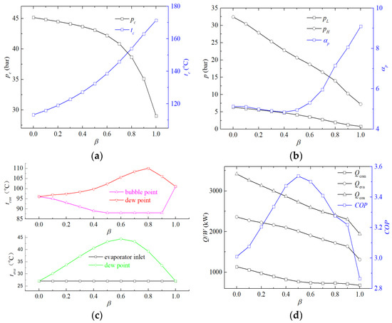
Figure 13.
The changes in the thermodynamic properties of the binary mixture R152a/R1336mzz(z) and the thermal performance of its corresponding heat pump cycle, with respect to the increase in the component R1336mzz(z) proportion. (a) the critical pressure and critical temperature; (b) the high pressure, low pressure, and pressure ratio; (c) the temperature glide of binary refrigerant in evaporator and condenser; (d) the power consumption of the compressor, the heat transfer quality of the condenser and COP of heat pump.
Figure 13c illustrates the temperature glide of the mixture refrigerant as it flows through the evaporator. This temperature glide does not necessarily represent the full temperature range change at a specific pressure value, as the evaporator inlet is in a gas–liquid two-phase state. Consequently, the evaporator’s temperature glide is defined as the difference between the dew point temperature at the evaporating pressure and 27 °C. Similarly, the condenser’s temperature glide is the difference between the dew point temperature and the bubble point temperature under the condensing pressure. As the temperature glide escalates, the bubble point temperature of the condenser declines compared to that of pure refrigerant, leading to a corresponding decrement in the high temperature and high pressure of the heat pump cycle. Consequently, the COP improves.
Figure 13c further highlights that the peak temperature glide values for the evaporator and condenser occur when the R1336mzz(z) component (β) is equal to 0.6 and 0.8, reaching up to 17.41 °C and 22 °C, respectively. However, Figure 13d demonstrates the peak COP value of 3.54 is observed when β is set to 0.5, representing a significant improvement compared to the heat pump using pure R1336mzz(z) refrigerant (2.87) and R152a refrigerant (3.01). As β increases, the heat transfer capacity of both the evaporator and condenser decreases almost linearly, indicating that the enthalpy change in the heat pump cycle with pure R1336mzz(z) refrigerant is relatively smaller compared to that with pure R152a refrigerant. This is due to the relatively small pressure difference in the heat pump cycle using pure R1336mzz(z) refrigerant. Furthermore, the gradient of compressor power consumption is relatively steep when β is small and gradually flattens out as β increases, leading to an optimal value being obtained at β equal to 0.5.
To deeply analyze the thermodynamic performance of LTVHP configurations using non-azeotropic mixtures with varying component proportions, Figure 14 presents their t-s diagrams. The operating parameters of LTVHP configurations using R1336mzz(z) and the R1336mzz(z)/R152a mixture with a ratio of 0.8/0.2, as shown in Figure 14a,e, are significantly distant from their critical points. Conversely, the configurations with R1336mzz/R152a mixtures of 0.2/0.8, 0.4/0.6, and pure R152a operate closer to their critical points. Both of these scenarios are disadvantageous for enhancing the thermal performance of the heat pump. Therefore, the COP of the LTVHP configuration using the R1336mzz(z)/R152a mixture with a ratio of 0.5/0.5 is maximized. In this case, the ratio of condensing temperature (calculated as the average of dew point and bubble point temperatures) to critical temperature is 0.72, which aligns with the conclusion outlined in Section 3.2.
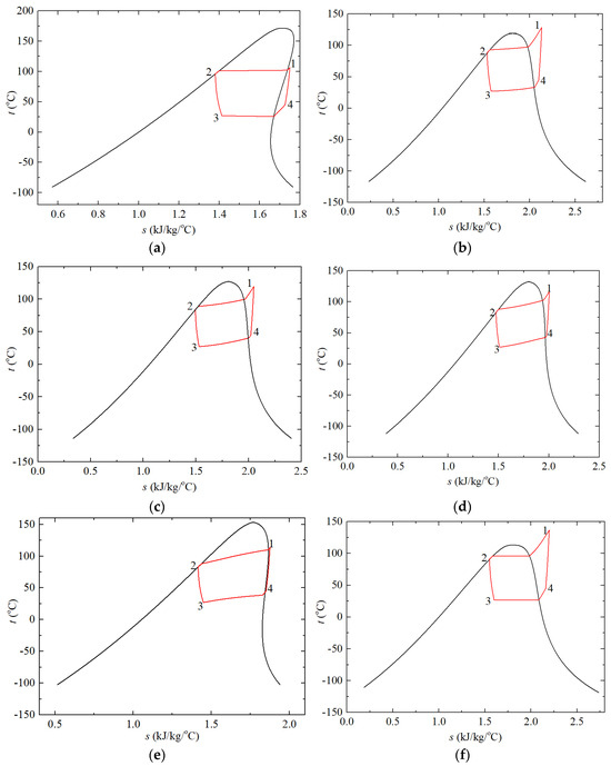
Figure 14.
t-s diagrams of the LTVHP configurations: (a) R1336mzz, (b) R1336mzz/R152a(0.2/0.8), (c) R1336mzz/R152a(0.4/0.6), (d) R1336mzz/R152a(0.5/0.5), (e) R1336mzz/R152a(0.8/0.2), (f) R152a.
4. Conclusions
Several configurations of LTVHP, utilizing various pure refrigerants, have been established. The thermodynamic parameters of the nodes have been calculated, and an investigation into the thermal performances of the cycle has been conducted. Moreover, to tackle the issue of temperature mismatch between hot and cold fluids in the evaporator and condenser, binary refrigerants have been utilized in LTVHP. Additionally, the fundamental mechanisms responsible for enhancing the thermal performance of these configurations have been explored. The key findings can be summarized as follows.
- (1)
- Multiple pure refrigerants with varying critical temperature levels have been utilized for the construction of LTVHP configurations. Taking into account three distinct thermal evaluation parameters—environmental friendliness, high efficiency, and compactness—different refrigerants can be recommended for use in LTVHP. Refrigerants such as R152a, R1234ze(z), R1233ze(e), and R245fa display relatively high heating capacity per unit mass. Furthermore, LTVHP systems utilizing refrigerants with high or very high critical temperature levels tend to exhibit higher COP.
- (2)
- A condensation temperature that is too close and too far from the critical temperature is not conducive to enhancing the performance of LTVHP. For a specific refrigerant used in LTVHP, optimal operating parameters within its normal operating range exist. Generally, the maximum COP for LTVHP is achieved when the temperature lift (δt) and pressure lift (δp) fall within the ranges of 0.62~0.71 and 0.36~0.5, respectively.
- (3)
- Binary refrigerant mixtures were introduced in a 0.5/0.5 proportion to establish LTVHP configurations. After conducting thorough research, it was discovered that the binary refrigerant mixture of R152a/R1336mzz(z) exhibited optimal performance under the current operating conditions, achieving a COP of 3.54. This represents a significant improvement in thermal performance compared to the use of pure R1336mzz(z) (COP = 2.87) and R152a (COP = 3.01).
- (4)
- The thermodynamic properties of the binary mixture R152a/R1336mzz(z) were calculated as the R1336mzz(z) component varied from 0 to 1.0, and the thermal performance of the corresponding heat pump was investigated. The results indicated that the maximum COP of 3.54 was observed when β was equal to 0.5, where the ratio of the condensing temperature to the critical temperature was 0.72.
Author Contributions
H.H.: Methodology, Investigation, Data Curation, Writing—Original Draft, Funding acquisition; F.Z.: Formal analysis, Writing—Original Draft; B.Z.: Formal analysis, Writing—Original Draft; T.W.: Conceptualization, Data Curation; Supervision, Funding acquisition; J.Q.: Conceptualization, Writing—Reviewing and Editing. All authors have read and agreed to the published version of the manuscript.
Funding
This research was funded by Fundamental Research Funds for the Central Universities (buctrc202138) and (buctrc202301).
Data Availability Statement
Data can be made available upon request from the authors.
Conflicts of Interest
There are no conflicts to declare.
Nomenclature
| Abbreviations | |
| LTVHP | large temperature variation heat pump |
| L | low temperature |
| H | high temperature |
| vH | very high temperature |
| M | medium temperature |
| LDT | lower end temperature |
| UDT | upper end temperature |
| PINPMIN | minimal value for pinch point |
| Symbols | |
| COP | coefficient of performance |
| cp | specific heat at constant pressure, kJ/(kg·°C) |
| h | enthalpy, kJ/kg |
| m | mass flow rate, kg/s |
| p | pressure, Pa |
| Q | heat transfer capacity, kW |
| s | entropy, kJ/kg |
| t | temperature, °C |
| W | electric energy, kW |
| V | volumetric flow rate, m3/s |
| Greek symbols | |
| αp | pressure ratio |
| η | efficiency, % |
| δ | thermodynamic parameter of optimal configuration deviating from the critical point |
| ε | ratio of boiling point temperatures at 1 bar pressure to critical temperature |
| β | the proportion of R1336mzz(z) component in R152a/R1336mzz(z) binary refrigerant |
| Subscripts | |
| bub | bubble point |
| com | compressor |
| crit | critical |
| dew | dewing point |
| i | inlet |
| ise | isentropic |
| m | unit mass |
| mech | mechanics |
| o | outlet |
| sat | saturated |
| V | unit volume |
| w | water |
| con | condensation |
| t | temperature |
| p | pressure |
References
- Yolcan, O.O. World energy outlook and state of renewable energy: 10-Year evaluation. Innov. Green Dev. 2023, 2, 100070. [Google Scholar] [CrossRef]
- Liu, Z.; Zhu, H.; Wilson, J.; Adams, M.; Walker, T.R.; Xu, Y.; Tang, Y.; Wang, Z.; Liu, T.; Chen, Q. Achieving China’s ‘double carbon goals’, an analysis of the potential and cost of carbon capture in the resource-based area: Northwestern China. Energy 2024, 292, 130441. [Google Scholar] [CrossRef]
- Siddik, M.; Islam, M.; Zaman, A.K.M.; Hasan, M. Current status and correlation of fossil fuels consumption and greenhouse gas emissions. Int. J. Energy Environ. Econ. 2021, 28, 103–119. [Google Scholar]
- Chen, J.M. Carbon neutrality: Toward a sustainable future. Innovation 2021, 2, 100127. [Google Scholar] [CrossRef] [PubMed]
- Brückner, S.; Liu, S.; Miro, L.; Radspieler, M.; Cabeza, L.F.; Lavemann, E. Industrial waste heat recovery technologies: An economic analysis of heat transformation technologies. Appl. Energy 2015, 151, 157–167. [Google Scholar] [CrossRef]
- Sulaiman, A.Y.; Cotter, D.; Wilson, C.; Kamkari, B.; Hewitt, N. Energetic and exergo-environmental analysis of transcritical high-temperature heat pumps with low GWP refrigerants for industrial waste heat recovery. Int. J. Refrig. 2023, 156, 12–28. [Google Scholar] [CrossRef]
- Vieren, E.; Demeester, T.; Beyne, W.; Magni, C.; Abedini, H.; Arpagaus, C.; Bertsch, S.; Arteconi, A.; De Paepe, M.; Lecompte, S. The Potential of Vapor Compression Heat Pumps Supplying Process Heat between 100 and 200 °C in the Chemical Industry. Energies 2023, 16, 6473. [Google Scholar] [CrossRef]
- Kosmadakis, G. Estimating the potential of industrial (high-temperature) heat pumps for exploiting waste heat in EU industries. Appl. Therm. Eng. 2019, 156, 287–298. [Google Scholar] [CrossRef]
- Arpagaus, C.; Bless, F.; Uhlmann, M.; Schiffmann, J.; Bertsch, S. High temperature heat pumps: Market overview, state of the art, research status, refrigerants, and application potentials. Energy 2018, 152, 985–1010. [Google Scholar] [CrossRef]
- Jiang, J.; Hu, B.; Wang, R.Z.; Deng, N.; Cao, F.; Wang, C.C. A review and perspective on industry high-temperature heat pumps. Renew. Sustain. Energy Rev. 2022, 161, 112106. [Google Scholar] [CrossRef]
- El Samad, T.; Żabnieńska-Góra, A.; Jouhara, H.; Sayma, A.I. A review of compressors for high temperature heat pumps. Therm. Sci. Eng. Prog. 2024, 51, 102603. [Google Scholar] [CrossRef]
- Vieren, E.; Demeester, T.; Beyne, W.; Andersen, M.P.; Elmegaard, B.; Arteconi, A.; Paepe, M.; Lecompe, S. Selection of pure and binary working fluids for high-temperature heat pumps: A financial approach. Appl. Therm. Eng. 2024, 252, 123615. [Google Scholar] [CrossRef]
- Hu, H.; Wang, T.; Jiang, Y.; Bi, C.; Zhang, B.; Fan, S.; Li, J.; An, S.; Bai, X.; Guo, C. Thermodynamic performance of heat pump with R1234ze(E)/R1336mzz(E) binary refrigerant. Appl. Therm. Eng. 2023, 230, 120795. [Google Scholar] [CrossRef]
- Mulroy, W.J.; Domanski, P.A.; Didion, D.A. Glide matching with binary and ternary zeotropic refrigerant mixtures Part 1. An experimental study. Int. J. Refrig. 1994, 17, 220–225. [Google Scholar] [CrossRef]
- Domanski, P.A.; Mulroy, W.J.; Didion, D.A. Glide matching with binary and ternary zeotropic refrigerant mixtures Part 2. A computer simulation. Int. J. Refrig. 1994, 17, 226–230. [Google Scholar] [CrossRef]
- Hamid, K.; Sajjad, U.; Ahrens, M.U.; Ren, S.; Ganesan, P.; Tolstorebrov, I.; Arshad, A.; Said, Z.; Hafner, A.; Wang, C.; et al. Potential evaluation of integrated high temperature heat pumps: A review of recent advances. Appl. Therm. Eng. 2023, 230, 120720. [Google Scholar] [CrossRef]
- Cop, M.; Barta, R.B.; Thomas, C.; Hesse, U. Experimental investigation of a heat pump tumble dryer with a zeotropic refrigerant mixture. Int. J. Refrig. 2024, 158, 190–201. [Google Scholar] [CrossRef]
- Ganesan, P.; Eikevik, T.M.; Hamid, K.; Wang, R.; Yan, H. Thermodynamic analysis of cascade high-temperature heat pump using new natural zeotropic refrigerant mixtures: R744/R600 and R744/R601. Int. J. Refrig. 2023, 154, 215–230. [Google Scholar] [CrossRef]
- Gómez-Hernández, J.; Grimes, R.; Briongos, J.V.; Marugán-Cruz, C.; Santana, D. Carbon dioxide and acetone mixtures as refrigerants for industry heat pumps to supply temperature in the range 150–220 °C. Energy 2023, 269, 126821. [Google Scholar] [CrossRef]
- Hakkaki-Fard, A.; Aidoun, Z.; Ouzzane, M. Improving cold climate air-source heat pump performance with refrigerant mixtures. Appl. Therm. Eng. 2015, 78, 695–703. [Google Scholar] [CrossRef]
- Zhang, S.; Wang, H.; Guo, T. Experimental investigation of moderately high temperature water source heat pump with non-azeotropic refrigerant mixtures. Appl. Energy 2010, 87, 1554–1561. [Google Scholar] [CrossRef]
- Zühlsdorf, B.; Bühler, F.; Mancini, R.; Cignitti, S.; Elmegaard, B. High temperature heat pump integration using zeotropic working fluids for spray drying facilities. In Proceedings of the Rotterdam: 12th IEA Heat Pump Conference, Rotterdam, The Netherlands, 15–18 May 2017. [Google Scholar]
- Bamigbetan, O.; Eikevik, T.; Neksa, P.; Bantle, M. Evaluation of natural working fluids for the development of high temperature heat pumps. In Proceedings of the 12th Iir Gustav Lorentzen Natural Working Fluids Conference, Edinburgh, UK, 21–24 August 2016; pp. 575–582. [Google Scholar]
- Park, K.J.; Seo, T.; Jung, D. Performance of alternative refrigerants for residential air-conditioning applications. Appl. Energy 2007, 84, 985–991. [Google Scholar] [CrossRef]
- Rashidi, M.M.; Mahariq, I.; Nazari, M.; Accouche, O.; Bhatti, M. Comprehensive review on exergy analysis of shell and tube heat exchangers. J. Therm. Anal. Calorim. 2022, 147, 12301–12311. [Google Scholar] [CrossRef]
- Quenel, J.; Anders, M.; Atakan, B. Propane-isobutane mixtures in heat pumps with higher temperature lift: An experimental investigation. Therm. Sci. Eng. Prog. 2023, 42, 101907. [Google Scholar] [CrossRef]
- Yelishala, S.C.; Kannaiyan, K.; Sadr, R.; Wang, Z.; Levendis, Y.A.; Metghalchi, H. Performance maximization by temperature glide matching in energy exchangers of cooling systems operating with natural hydrocarbon/CO2 refrigerants. Int. J. Refrig. 2020, 119, 294–304. [Google Scholar] [CrossRef]
- Zühlsdorf, B.; Jensen, J.; Cignitti, S.; Madsen, C.; Elmegaard, B. Analysis of temperature glide matching of heat pumps with zeotropic working fluid mixtures for different temperature glides. Energy 2018, 153, 650–660. [Google Scholar] [CrossRef]
- Abedini, H.; Vieren, E.; Demeester, T.; Beyne, W.; Lecompte, S.; Quoilin, S.A. comprehensive analysis of binary mixtures as working fluid in high temperature heat pumps. Energy Convers. Manag. 2023, 277, 116652. [Google Scholar] [CrossRef]
- Venkatarathnam, G.; Murthy, S. Effect of mixture composition on the formation of pinch points in condensers and evaporators for zeotropic refrigerant mixtures. Int. J. Refrig. 1999, 22, 205–215. [Google Scholar] [CrossRef]
- Cheng, Z.; Wang, B.; Shi, W.; Li, X. Numerical research on R32/R1234ze(E) air source heat pump under variable mass concentration. Int. J. Refrig. 2017, 82, 1–10. [Google Scholar] [CrossRef]
- d’Angelo, J.V.H.; Aute, V.; Radermacher, R. Performance evaluation of a vapor injection refrigeration system using mixture refrigerant R290/R600a. Int. J. Refrig. 2016, 65, 194–208. [Google Scholar] [CrossRef]
- Guo, H.; Gong, M.; Qin, X. Performance analysis of a modified subcritical zeotropic mixture recuperative high-temperature heat pump. Appl. Energy 2019, 237, 338–352. [Google Scholar] [CrossRef]
- Tanaka, K.; Higashii, Y.; Akasaka, R. Thermodynamic property modeling of HFO-1234ze (E)+ HFC-32 mixtures for evaluating cycle performance. In Proceedings of the 23rd IIR International Congress of Refrigeration, Prague, Czech Republic, 21–26 August 2011. [Google Scholar]
- Thu, K.; Takezato, K.; Takata, N.; Miyazaki, T.; Higashi, Y. Drop-in experiments and exergy assessment of HFC-32/HFO-1234yf/R744 mixture with GWP below 150 for domestic heat pumps. Int. J. Refrig. 2021, 121, 289–301. [Google Scholar] [CrossRef]
- Fleckl, T.; Hartl, M.; Helminger, F.; Kontomaris, K. Performance Testing of a Lab-Scale High Temperature Heat Pump with HFO-1336mzz-z as the Working Fluid; European Heat Pump Summit: Nuremberg, German, 2015. [Google Scholar]
- Bobelin, D.; Bourig, A.; Peureux, J.L. Experimental results of a newly developed very high temperature industrial heat pump (140 °C) equipped with scroll compressors and working with a new blend refrigerant. In Proceedings of the International Refrigeration and Air Conditioning Conference, West Lafayette, IN, USA, 16–19 July 2012. [Google Scholar]
- Fukuda, S.; Kondou, C.; Takata, N.; Koyama, S. Low GWP refrigerants R1234ze(E) and R1234ze(Z) for high temperature heat pumps. Int. J. Refrig. 2014, 40, 161–173. [Google Scholar] [CrossRef]
- Verdnik, M.; Rieberer, R. Influence of operating parameters on the COP of an R600 high-temperature heat pump. Int. J. Refrig. 2022, 140, 103–111. [Google Scholar] [CrossRef]
- Hu, H.; Jiang, Y.; Guo, C.; Liang, S. Thermodynamic and exergy analysis of a S-CO2 Brayton cycle with various of cooling modes. Energy Convers. Manag. 2020, 220, 113110. [Google Scholar] [CrossRef]
- Sun, S.; Guo, H.; Gong, M. Thermodynamic analysis of single-stage compression air-source heat pumps with different recuperation ways for large temperature lift. Int. J. Refrig. 2019, 108, 91–102. [Google Scholar] [CrossRef]
- Chen, J.; Chen, Q.; Qin, X.; Wang, D. Energy, exergy, economic and environmental analyses and optimization of a novel vapor injection autocascade heat pump for high-temperature water heating. Energy Convers. Manag. 2022, 267, 115909. [Google Scholar] [CrossRef]
- Hu, H.; Li, Z.; Jiang, Y.; Du, X. Thermodynamic characteristics of thermal power plant with hybrid (dry/wet) cooling system. Energy 2018, 147, 729–741. [Google Scholar] [CrossRef]
- Zhu, Y.; Zhai, R.; Qi, J.; Yang, Y.; Reyes-Belmonte, M.A.; Romero, M.; Yan, Q. Annual performance of solar tower aided coal-fired power generation system. Energy 2017, 119, 662–674. [Google Scholar] [CrossRef]
- Vandersickel, A.; Wedel, W.G.; Spliethoff, H. High temperature heat and water recovery in steam injected gas turbines using an open absorption heat pump. Appl. Therm. Eng. 2020, 165, 114663. [Google Scholar] [CrossRef]
- Li, P.; Nord, N.; Ertesvåg, I.S.; Ge, Z.; Yang, Z.; Yang, Y. Integrated multiscale simulation of combined heat and power based district heating system. Energy Convers. Manag. 2015, 106, 337–354. [Google Scholar] [CrossRef]
- Zhao, S.; Ge, Z.; He, J.; Wang, C.; Yang, Y.; Li, P. A novel mechanism for exhaust steam waste heat recovery in combined heat and power unit. Appl. Energy 2017, 204, 596–606. [Google Scholar] [CrossRef]
- Hu, H.; Wang, T.; Ren, Y.; Zhang, F.; Zhang, B.; Li, J. A case study of thermal performance of gas-steam combined cycle with gas turbine inlet air cooling and condenser deep cooling. Case Stud. Therm. Eng. 2024, 60, 104747. [Google Scholar] [CrossRef]
Disclaimer/Publisher’s Note: The statements, opinions and data contained in all publications are solely those of the individual author(s) and contributor(s) and not of MDPI and/or the editor(s). MDPI and/or the editor(s) disclaim responsibility for any injury to people or property resulting from any ideas, methods, instructions or products referred to in the content. |
© 2024 by the authors. Licensee MDPI, Basel, Switzerland. This article is an open access article distributed under the terms and conditions of the Creative Commons Attribution (CC BY) license (https://creativecommons.org/licenses/by/4.0/).