Abstract
In the process of the on–board transportation of liquid hydrogen storage and transportation tanks, apart from considering the support strength and adiabatic performance, it is imperative to take into account the vibration characteristics of the carrying platform. The present work introduces a versatile support structure comprising a damping module and a ball contact insulation structure, enabling effective isolation of external vibrations while simultaneously providing support and insulation. The first step involves describing the principle of a flexible support structure and designing the mechanical structure. Subsequently, a damping analysis is conducted based on dynamic theory to establish the relationship between the spring and damping. Finally, the structural parameters of the dual–function strut are determined, followed by simulation of heat transfer performance. The results demonstrate that the dual–function strut exhibits exceptional vibration damping performance by reducing the amplitude of external vibrations greater than 5 Hz to less than 6%. Moreover, owing to the compact linear diameter spring structure of the vibration damping module and its ball contact effect, the thermal resistance of the dual–function strut is significantly enhanced, resulting in a mere heat leakage of only 22 W/m2 in a single rod section.
1. Introduction
Two primary forms of energy that are most relevant to human beings are thermal energy and electrical energy, both of which heavily rely on fossil fuels (80–85%). Notably, coal accounts for 39% of the world’s total electricity generation [1]. The main concern with coal is that power plants fueled by coal contribute to nearly 30% of global CO2 emissions [2].
Hydrogen energy is a form of clean energy characterized by zero carbon emissions and versatile applications. It serves as an ideal medium for storing renewable energy and balancing peak demands, thereby accelerating the deep decarbonization of power, industry, transportation, construction, and other sectors [3]. Moreover, it is expected to play a significant role in promoting global energy transformation. The production of hydrogen offers flexibility, particularly through wind power and photovoltaic generation technologies that enable achieving zero carbon emissions [4,5]. Currently, hydrogen development has garnered considerable attention worldwide. Taking China as an example, research and analysis predict that the demand for hydrogen will reach approximately 6 × 107 t by 2050, with its share in the energy system increasing to 10% [6]. The concept of “the utilization of hydrogen as an energy storage medium for electricity” offers a viable solution to tackle the challenges associated with curtailment issues encountered by renewable energies like wind and solar power, while simultaneously ensuring an abundant supply of hydrogen in the future. However, there are still major hurdles in the advancement of hydrogen energy. Hydrogen exists as a gas at room temperature and pressure with a density only amounting to 7.14% of that of air, which results in relatively low volumetric energy density compared to natural gas (approximately one–third at 20 MPa). Therefore, developing high–mass–fraction or high–energy–density storage and transportation technologies for hydrogen is crucial for enabling large–scale utilization of this form of clean energy [7].
The available methods for storing and transporting hydrogen primarily include high–pressure gas storage/transportation systems, cryogenic liquid storage/transportation systems, organic liquid storage/transportation systems, and solid–state adsorption storage/transportation technologies. Among them, the storage mass fraction of liquid hydrogen is the greatest due to its saturation density at atmospheric pressure being approximately 70.8 kg/m3, which is 845 times greater than that of gaseous hydrogen. However, the challenges faced by liquid hydrogen storage and transportation technology are evident as it relies on cryostorage methods. The saturation temperature of liquid hydrogen under normal pressure is around 20 K, posing design difficulties for the crucial component: the liquid hydrogen storage tank. On the one hand, there exists a significant temperature disparity between the container and its surroundings. Despite employing special adiabatic measures, some heat leakage occurs, necessitating highly efficient insulation for non–destructive storage [8]. On the other hand, any leaks in the liquid hydrogen storage system can have severe consequences [9].
At present, there has been a lot of research on the insulation of liquid hydrogen storage tanks, and advanced technical approaches are focused on insulation/thermal management of vacuum–variable density–multilayer insulation–vapor–cooling shields. The insulation requirements for storage tanks vary depending on the amount of boil–off. Generally, liquid hydrogen requires cryogenic storage technology, which minimizes heat flux by stacking multiple insulation layers in a high vacuum (10−1–10−5 Pa). However, large–scale tanks use a medium vacuum (102–10−1 Pa) to reduce maintenance expenses. Solid insulation is applied to prevent liquefaction of residual gas up to 150 K, followed by the stacking of multilayer insulation with a vapor–cooling shield to minimize the insulation thickness [10]. This is because the cryogenic tanks generally require a comprehensive consideration of technology [11].
In addition to the insulation layer itself, the support structure is also a crucial component that connects the low–temperature inner tank and the normal–temperature outer tank. Further attention is required for its design and research [8]. Studies have indicated that the heat leakage from the support structure in the tank accounts for a significant proportion, which adversely affects the uniformity of liquid hydrogen’s temperature field in the tank, thereby significantly reducing its non–boil–off time [12]. Another study has highlighted that as a thermal bridge between the inner liner and shell, the support structure often generates thermal leakage heat exceeding 30% of total heat leakage. Hence, it is imperative to carefully design this support structure by selecting materials with low thermal conductivity, minimizing its cross–sectional area and increasing its effective adiabatic length, in such a way as to reduce heat leakage as much as possible [13]. Shao X. et al. [14] employed the CFD method to numerically calculate the heat transfer and strength of storage tanks while verifying adiabatic performance through experiments on hydrogen storage tanks with adiabatic support structures. They obtained high–performance parameters with a leakage heat flux less than 1.4 W/m2 and hydrogen storage density of 39.4%. Li J. et al. [15], in their analysis of cryogenic propellant thermal management technology progress and application in launch vehicles, emphasized the thermal conductivity of tank connection structures while illustrating optimal insulation materials for connecting liquid oxygen and liquid hydrogen tanks on Titan rockets. They found that heat leakage from these 12 connecting components was approximately 0.2 W [16]. Notably, achieving a cooling capacity of 0.2 W at a temperature of 20 K would require consuming about 100 W by refrigeration systems [17].
Different applications of liquid hydrogen storage tanks have varying structures. They are commonly found in the typical forms of spherical storage tanks and cylindrical dewar tanks. Xu W. et al. [18] conducted an analysis on the structural design and strength of a UAV’s airborne cryogenic liquid hydrogen storage tank, emphasizing that adiabatic tanks are generally either spherical or cylindrical. It is worth noting that a cylindrical tank with the same capacity has a larger surface area compared to a spherical tank due to its shape. Additionally, the cylinder tank requires a thicker wall because it operates at higher internal pressures. The use of cylindrical tanks also necessitates minimal shaking to ensure weight balance along its entire length, which calls for vibration isolation in addition to insulation for the supporting structure [19]. For instance, when considering truck transportation on conventional pavement, vibrations caused by acceleration can reach approximately 0.5 g and increase significantly with speed acceleration. The exciting frequency falls within 200 Hz, while the main frequency ranges from 1 Hz to 10 Hz. With large amplitudes, accelerations can exceed 1 g and potentially damage the tank support rod [20].
The simple supporting rod is the most commonly used structure in practice. NASA initially proposed a passive orbital disconnect strut (PODS), which involves heat transfer through the pin and rod when subjected to heavy loads. However, when the load is light, there is no contact between the pin and rod, resulting in heat transfer solely through the rod. This modification significantly reduces heat leakage from the tank by altering the path of heat transfer [21]. Zheng Z. et al. [22] analyzed the new PODS support structure considering both load–bearing capacity and heat leakage issues associated with low–temperature storage tank connection supports. They conducted simulations to evaluate force and thermal characteristics under different operating conditions. The research findings indicate that at a cold–end temperature of 2 K, hot–end temperature of 300 K, and ambient temperature of 273 K, heat leakages in non–contact state, tension state, and pressure state are calculated as 0.114 W, 0.142 W, and 0.143 W, respectively, using heat flux conversion methods. Heat leakage in non–contact state is approximately 20% lower than that in contact state. Another innovative structure known as ceramic ball–gasket combined point–contact adiabatic support has demonstrated excellent thermal insulation performance along with its supporting capability [23]. Relevant studies have indicated that this proposed innovative combined point–contact adiabatic support structure can reduce heat leakage by over 90% compared to conventional boom supports.
To conclude, with the development of liquid hydrogen for civilian purposes, it is crucial to address not only heat insulation and structural strength, but also the emerging challenges posed by vibration during its transportation. However, research in this particular domain remains insufficient. This paper proposes a dual–function support structure that combines thermal insulation and vibration attenuation capabilities. The theoretical analysis and simulation conducted herein aim to validate the feasibility of employing flexible supports in low–temperature storage tanks.
2. Design Scheme of Dual–Function Strut
The core section of the dual–function strut comprises a vibration damping module, a ball contact thermal insulation module, and two sections of rod. The vibration damping module consists of a spring damping system, while the ball contact thermal insulation module is a locking structure made up of a composite ball and multiple ceramic balls. Both sections of the rod are constructed from the same composite material. Its structure is depicted in Figure 1. The spring damping module comprises two opposing assembly springs, a damping pool, and a stabilizer bar. A hole plate is provided at the end of the stabilizer bar to interact with the working medium in the damping pool for achieving the dampening effect. The restraint mechanism for the end utilizes ceramic ball–to–ball contact, allowing planar contact between ceramic balls and restraints. The restraint shell is connected to an outer supporting tank and employs a two–layer three–point constraint method for restraining the end. The spherical design of the end provides three degrees of freedom to maintain flexibility during small rotations. The triangular structure of the restraint shell ensures that only six adiabatic balls are used for locking purposes. Three–point constraint refers to each adiabatic ball being tangentially in contact with two adjacent surfaces of the restraint shell.
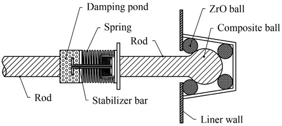
Figure 1.
Scheme of dual–function struct.
The key parameters of the 50 L liquid hydrogen storage tank sample used in this paper are shown in Table 1.

Table 1.
Key parameters of 50 L liquid hydrogen storage tank.
3. Dynamic Analysis of Dual–Function Strut
In order to effectively attenuate the vibration transmitted to the inner wall of the tank, we intended to analyze the dynamic relationships among the spring, mandrel, and damper. A dynamic equation is established based on the target load and given impact. Subsequently, a parameter setting scheme for the stiffness coefficient, stroke, damping coefficient, module stiffness, and spring strength is discussed. Finally, various input signals are simulated to evaluate the response of the dual–function strut.
3.1. Analysis of Damping Module
Through schematic analysis of the damping module, the vibration model of the damping module can be simplified and described, as depicted in Figure 2. The two ends of the damping module are, respectively, connected to the inner liner and outer shells through composite rods (which are rigid). The vibration from the outer shell transmits to the damping module via the rigid rod. By utilizing spring assembly and damping mechanisms, the transmission of vibrations to the inner liner will be effectively attenuated. In order to achieve optimal attenuation performance, specifically minimizing vibrations within the inner tank, a dynamic analysis of the damping module is conducted along with an examination of how input signal x2 influences the response x1 within this context.
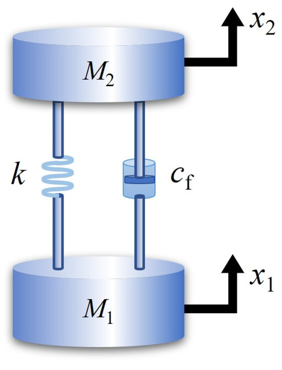
Figure 2.
Diagram of dynamics of damping module.
Newton’s second law is used to describe the dynamic equation for the vibration reduction model, as shown in Equation (1):
where x1 and x2 are response displacement and exciting displacement, respectively. M1 is the total weight of liner, M2 is the weight of outer shell (if the outer shell is fixed on the transporting platform, M2 is the total weight of the shell and the transporting platform), k is the stiffness coefficient of the spring, and cf is the damping coefficient. The function p(t) is the instantaneous input force.
Considering that M1 is a free end so that p(t) = 0,
Then, use Laplace transform to convert Equation (2) to Equation (3):
The transfer function from X2(S) to X1(S) is obtained as shown in Equation (4).
The transfer function analysis reveals that the denominator is a quadratic equation with one variable. By assuming the denominator to be equal to zero, the equation is examined through its roots. In accordance with the second–order response theory, to minimize vibration within the internal tank, it is imperative for the damping ratio of the second–order system to at least attain critical damping, i.e., a damping ratio of unity. This can be observed in Equation (5).
In addition to the critically damped state, there are also underdamped and overdamped states. In the underdamped state, the internal tank will vibrate in response to input vibrations, but the amplitude will gradually decrease until it reaches an equilibrium state after a certain period of time. When critical damping is achieved, the internal tank will reach an equilibrium state with minimal vibration. Overdamping prolongs the time required to reach equilibrium beyond that of critical damping. Equation (5) is derived to establish the relationship between the damping coefficient, spring stiffness, and tank mass. Among these variables, the mass of the internal storage tank is known; specifically, it consists of 17.91 kg from all materials comprising the inner tank composite and an additional 3.51 kg from 45 L of liquid hydrogen for a total weight of 21.42 kg.
The dual–function struts installed between the liner and outer shall of the tank can be divided into either six or twelve pairs depending on different operating conditions. During vertical vibrations of the tank (without considering lateral vibrations at this stage), all struts function simultaneously. Therefore, M1 in the equation should represent either one–sixth or one–twelfth of the total mass depending on whether six or twelve pairs of struts are used, respectively.
The choice between these two installation options will impact both damping coefficient and spring stiffness selection as explained in detail later on. Considering installation with six pairs of struts, M1 represents one–twelfth of the total mass (each group consisting of two support rods). The relationship between cf and k is shown in Equation (6):
The critical damping condition implies a direct relationship between cf and k, which is a one–to–one correspondence.
In fact, the process of Equation (5) to (6) yields a specific scenario. When considering various conditions, including 6 sets of supports resulting in system operation within 3 g acceleration and 12 sets of supports resulting in system operation within 15 g acceleration, the relationship between the damping and stiffness coefficients of the spring is depicted in Figure 3. It can be observed from Figure 3 that achieving the same damping effect requires adjusting cf with k based on the number of separate damping rods installed. The greater the number of installed damping rods, the more gradual the change in the damping coefficient with spring stiffness becomes. Consequently, for a given spring, one can select damping devices with lower damping coefficients. There exists a direct correspondence between the damping coefficient and spring stiffness. Thus, this finding can serve as a reference when selecting spring and damping devices.
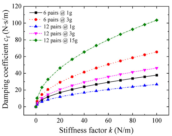
Figure 3.
cf–k under different scenarios.
3.2. Simulation of Damping Module Response
After obtaining the corresponding relationship between cf and k, the response of x1 to different inputs x2 can be further simulated. The calculation process is implemented using MATLAB programming language. Here, k is set to 1 unit, and the calculation time needs to consider the actual load loading frequency. If the loading frequency of the actual driving load on the road falls within the range of 1 Hz~102 Hz, then it is necessary to control the calculation time within 1~0.01 s. For ease of analysis and observation, it can be appropriately extended to 0.2 s.
3.2.1. Analysis of Single–Step Excitation Response
By inputting a unit step signal at time 0, we obtain both the response curve and signal input curve as shown in Figure 4. In case of an input unit step signal (which remains unchanged after loading), we observe that there is a jump start point for response at time 0. When reaching a time period of 0.2 s, we find that the response value for the inner tank reaches approximately 0.27 units.
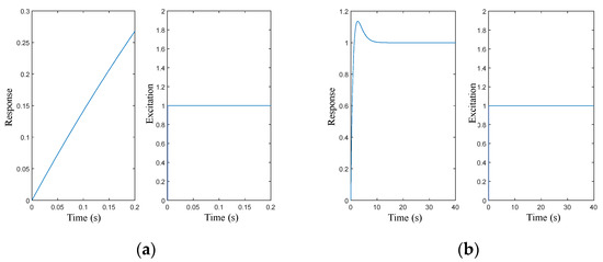
Figure 4.
Single–step excitation response. (a) Input signal and maintaining 0.2 s; (b) input signal and maintaining to the steady state.
The response value initially exceeds unity before stabilizing for longer response times. The periodic nature of actual vibrations, with very short durations for each vibration cycle, results in the production of an effective vibration damping effect by the vibration damping module.
The calculation time in Figure 4b is extended compared to Figure 4a in order to observe the change in the overall response curve. It can be observed that the vibration amplitude of the response curve exceeds 1 for a certain period of time and then gradually decreases to 1. This phenomenon is attributed to the difference in transfer function, where an additional primary term on the numerator leads to vibration occurrence. Considering the loading frequency of the actual load, it can be seen that changes occur in the input signal before vibration happens, and the vibration damping system achieves an effective damping effect.
3.2.2. Continuous Excitation Response Analysis
In order to better simulate continuous vibrating input signals similar to actual conditions, it is more appropriate to replace pulse functions with sine functions as inputs. Therefore, further analysis is conducted on responses under different loading frequencies, as shown in Figure 5. Figure 5a presents calculation results for a loading frequency of 5 Hz. It can be observed that for the unit input signal, the amplitude reaches stability within one cycle (i.e., 0.2 s), accounting for approximately 6% of the loaded signal strength and significantly weakened compared to initial values. In contrast, the mean vibration response is influenced by the initial load direction and gradually returns from maximum deviation back towards zero within about 2.5 s until reaching a stable state while keeping the loading signal unchanged.
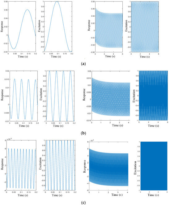
Figure 5.
Response results of different frequencies of sinusoidal input. (a) Results of 5 Hz sinusoidal input, both 0.2 s simulation period and until equilibrium state. (b) Results of 20 Hz sinusoidal input, both 0.2 s simulation period and until equilibrium state. (c) Results of 50 Hz sinusoidal input, both 0.2 s simulation period and until equilibrium state.
Compared with Figure 5b,c, under different loading frequencies, the amplitude of the response signal clearly varies with frequency; higher frequencies result in weaker amplitudes, indicating that better vibration reduction effects under high–frequency vibrations are achieved. Subsequently, deviations in vibrations are observed over time.
3.3. Parameter Design for the Strut
Based on the aforementioned analysis, the parameters of the damping spring can be determined. For quicker analysis, a single spring is used instead of a spring group, while maintaining consistent stiffness. The total mass of the onboard liquid hydrogen storage tank is 21.42 kg, supported by 6 pairs of struts. To ensure that the maximum deformation of the springs does not exceed 10 mm under a load of 1 g acceleration, the spring constant is required to be 1.75 kN/m. Additionally, due to spatial constraints, the original length of the springs must not exceed 40 mm, with a compressed length of 30 mm. The spring’s parameters are shown in Table 2.

Table 2.
Spring parameters (304 stainless steel).
Regarding the modeling of the damping module, the main considerations are the preload force of the installed spring and the form matching of the damper. Figure 6 shows the assembly structure of the vibration reduction module combined with a spring and damper. Considering the space constraints for installation, the diameter of the vibration reducer is 21 mm, and the total length is 44 mm. The design of the damper is currently incomplete. Since the damper may operate in the −50 °C low–temperature range and under vacuum conditions, gas pressure or oil pressure dampers cannot be used. Therefore, it is proposed to use an elastic strain damper.
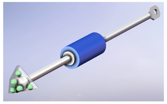
Figure 6.
Model of the strut.
Regarding the optimization of the rod length, in principle, the cold–end rods should be as long as possible while the hot–end rods should be relatively shorter under the installation space running conditions. As analyzed previously, due to the large length–to–diameter ratio of the rods, the temperature gradient along the rod direction is the biggest. The longer the cold–end rod, the higher the temperature that the vibration reduction module can reach, which facilitates the material selection for the vibration reduction module to operate in the high–temperature range. The effective length of the support rod is 217 mm. The model of the strut is shown in Figure 6.
4. Simulation of Thermal Insulation Performance
The goal of the system analysis is to obtain the force state and heat transfer characteristics of the rods during operation. The tank body is modeled according to the relevant parameters of the inner tank given in Table 1. The tank body adopts the new struts, and the overall structure diagram is shown in Figure 7. It primarily includes the necessary components for analysis, such as the liner, connecting rings, connecting hinges, struts, and outer shell.
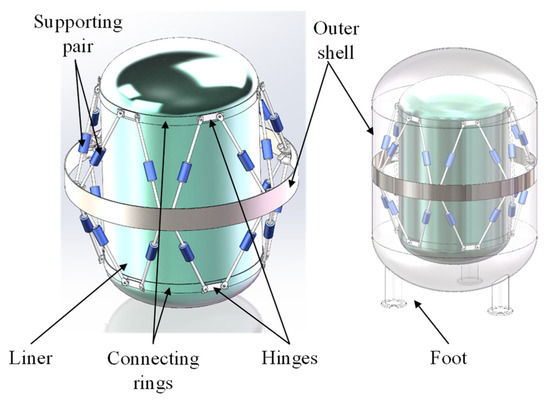
Figure 7.
Overall structure diagram of the tank.
The support rods are arranged in pairs, with the low–temperature ends of two rods connected to the same hinge. The hinge is fixed to the inner tank. The directions of the two rods form a certain angle. Combined with the overall structure diagram of the storage tank, the inner tank connections and outer shell connections of the support rods are distributed circumferentially with an offset angle of 30°. Upon constraining both the inner and outer contact mechanism, a stable multi–triangular support structure was obtained.
4.1. Simulation Model
Figure 8 illustrates the simulation model of dual–function struts. The model comprises a set of hinged corner pieces, two sets of rods, and two sets of support ends. To simplify the finite element analysis, the middle portion is modeled as an elastic part. The two support ends consist of six zirconia insulating balls and a limiting box that constrains the displacement of the struts. The zirconia balls establish tangential, or point, contacts with the limiting box and the rod ball joints.

Figure 8.
A pair assembly model.
The materials employed in this study are zirconia, 304 stainless steel, and composite fiberglass (FRP). Their material properties are listed in Table 3:

Table 3.
Material properties.
For mesh segmentation, complex regions need to be segmented into partial regions to facilitate swept or structured mesh generation. For the constraint box component, which exhibits high symmetry, a symmetric segmentation approach is employed. A global seed size of 0.5 mm is specified, with denser seeding in rounded corner regions using localized seed assignment.
The cell type chosen for the analysis is the linear DC3D4 (standard) cell in the implicit solver, which is a tetrahedral first–order linear cell suitable for analyzing the heat transfer characteristics. The mesh comprises 357,946 elements and 411,296 nodes, with a unit aspect ratio error of 0.
4.2. Numerical Analysis of Heat Transfer
After completing the calculation, the temperature field cloud of the rod system at heat transfer equilibrium is shown in Figure 9.
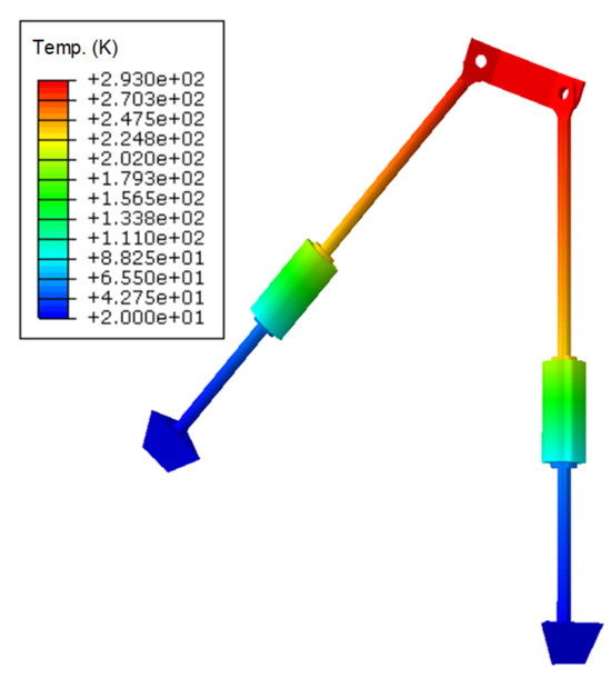
Figure 9.
Temperature cloud diagram of the struts.
It can be observed that the temperature decreases gradually from the room temperature section to the liquid hydrogen low–temperature section, and the temperatures of the two rods exhibit a symmetric distribution. Within the FRP section, the temperature distribution is uniform in the high–temperature region, and a sudden temperature drop occurs in the elastic section. This is due to the low thermal conductivity of the elastic section, which is 0.0049 W/(m·K), approximately 1/40 times that of the FRP. The temperature ultimately drops to 20 K at the cold end.
The temperature field cloud diagrams of the subcomponents are shown in Figure 10.
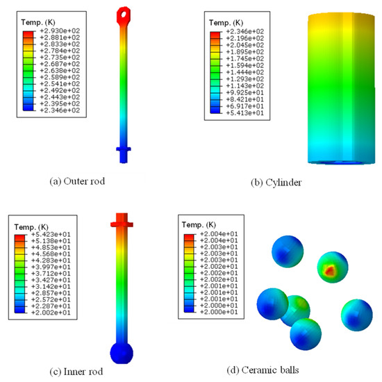
Figure 10.
Temperature field cloud diagrams of the subcomponents.
The result reveals that the overall temperature gradient distribution of the strut is significant, mainly attributed to the large length–to–diameter ratio of the rod. Additionally, the use of composite materials with a low thermal conductivity of only 0.2 W/(m2·K) contributes to this effect. The temperatures on both sides of the damping module are 235 K and 54 K, respectively, indicating a substantial thermal gradient across the damping module. This is primarily due to the very large length–to–diameter ratio of the spring wires, resulting in a large overall thermal resistance, even with the use of stainless–steel materials. Observations of the ceramic ball show a relatively small temperature gradient and a uniform temperature distribution. Two factors contribute to this: first, the ceramic ball’s small size, with a diameter of 5 mm, and its thermal conductivity of 1.4 W/(m2·K), which makes it difficult to form large temperature gradients. However, the main role of the ceramic ball is to significantly reduce the conductive area for axial heat transfer along the strut, creating a “bottleneck” for heat flow, making it challenging for heat to rapidly reach the other end.
The temperature distribution curve along the length of the strut is illustrated in Figure 11. It can be observed that both the vibration damping module and the ball contact region exhibit a larger temperature gradient, with consistent slopes in their respective temperature profiles. This can be attributed to the higher thermal resistance of the vibration damping module and the additional contact thermal resistance introduced by the ball contact.
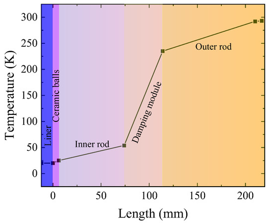
Figure 11.
Temperature distribution curve along the rod length direction.
Overall, the thermal conduction rate of a single rod is approximately 6.1351 × 10⁻⁴ W, which is equivalent to the heat flux of 22 W/m2, compared to the heat flux of the strut in Ref. [23], which is about 49 W/cm2. The findings presented in this paper constitute only 45% of the results reported in the reference.
5. Conclusions
With the advancement of liquid hydrogen civilianization, the transportation environment for liquid hydrogen storage and transportation equipment has become increasingly complex and challenging. Traditional support structures that solely consider thermal insulation and strength can no longer adapt to transportation working conditions with complex vibrations. In this paper, a dual–function strut is proposed, and a 50 L liquid hydrogen tank is used as the object to carry out the structural design and vibration damping dynamics analysis of the strut, followed by heat transfer simulation. This study yields the following conclusions:
- (1)
- The total weight of the liner and its collateral material is 21.42 kg, which is supported by six pairs of dual–function struts. When the damping ratio reaches the critical damping ratio, there exists a one–to–one correspondence between the damping coefficient cf and the spring stiffness coefficient k. For a unit value of k, cf is equal to 2.672 N·s/m.
- (2)
- The damping effect of the dual–function strut is closely correlated with the loading frequency. As the frequency increases, the amplitude response decreases proportionally. Moreover, when the loading frequency exceeds 5 Hz, the amplitude response remains below 6% of the loading signal strength.
- (3)
- Thanks to incorporating a fine–diameter spring structure in its damping module and a ball–contact insulating structure in the end connection, the dual–function strut exhibits significantly enhanced thermal resistance, resulting in an impressively low heat leakage rate of only 22 W/m2 within a single rod cross–section.
Author Contributions
Conceptualization, X.M.; Methodology, Y.Q.; Software, J.X.; Formal analysis, J.X.; Investigation, Y.X.; Resources, Y.X.; Data curation, J.X.; Writing—original draft, Y.Q.; Writing—review & editing, H.K.; Supervision, X.M.; Funding acquisition, X.M. All authors have read and agreed to the published version of the manuscript.
Funding
This work is supported by the fund of the State Key Laboratory of Technologies in Space Cryogenic Propellants, SKLTSCP202206.
Data Availability Statement
The original contributions presented in the study are included in the article, further inquiries can be directed to the corresponding author.
Conflicts of Interest
We declare that we do not have any commercial or associative interests that represent a conflict of interest in connection with the work submitted.
References
- Banerjee, T.; Bravo, J.; Sarunac, N.; D’Agostini, M.; Romero, C.; Banerjee, T.; Bravo, J.; Sarunac, N.; D’Agostini, M.; Romero, C. Sustainable energy storage solutions for coal–fired power plants: A comparative study on the integration of liquid air energy storage and hydrogen energy storage systems. Energy Convers. Manag. 2024, 310, 118473. [Google Scholar] [CrossRef]
- Sources of Greenhouse Gas Emissions | US EPA. 2022. Available online: https://www.epa.gov/ghgemissions/sources-greenhouse-gas-emissions (accessed on 5 November 2023).
- Ley, M.B.; Meggouh, M.; Moury, R.; Peinecke, K. Development of hydrogen storage tank systems based on complexmetal hydrides. Materials 2015, 8, 5891–5921. [Google Scholar] [CrossRef] [PubMed]
- Yang, P.; Zhu, W.; He, Y. Study on wide power characteristics of water electrolysis hydrogen production plant under fluctuating hydrogen production conditions. Ionics 2024, 30, 2767–2781. [Google Scholar] [CrossRef]
- Li, J.; Liang, Z.; Li, G.; Song, J.; Xu, G. Analysis of key technologies for solar hydrogen production. Acta Energiae Solaris Sin. 2022, 3, 2–11. [Google Scholar]
- Cao, J.; Qin, X.; Geng, G.; Zhang, W.; Yu, B. Current Status and Prospects of Hydrogen Storage and Transportation Technology. Acta Pet. Sin. (Pet. Process. Sect.) 2021, 37, 1461–1478. [Google Scholar]
- Morales–Ospino, R.; Celzard, A.; Fierro, V. Strategies to recover and minimize boil–off losses during liquid hydrogen storage. Renew. Sustain. Energy Rev. 2023, 182, 113360. [Google Scholar] [CrossRef]
- Lee, H.; Brilianto, R.M.; Lee, S.S.; Kim, C. Design and structural safety verification of the tank trailer for liquid hydrogen transport. J. Mech. Sci. Technol. 2024, 38, 671–681. [Google Scholar] [CrossRef]
- Cirrone, D.; Makarov, D.; Molkov, V. Rethinking “BLEVE explosion” after liquid hydrogen storage tank rupture in a fire. Int. J. Hydrogen Energy 2023, 48, 8716–8730. [Google Scholar] [CrossRef]
- Kang, D.-H.; An, J.-H.; Lee, C.-J. Numerical modeling and optimization of thermal insulation for liquid hydrogen storage tanks. Energy 2024, 291, 130143. [Google Scholar] [CrossRef]
- Xu, X.; Zhou, Q.; Yu, D. The future of hydrogen energy: Bio–hydrogen production technology. Int. J. Hydrogen Energy 2022, 47, 33677–33698. [Google Scholar] [CrossRef]
- Wang, H.; Wang, B.; Sun, J.; Pan, Q.; Luo, G.; Tao, X.; He, Y.; Pfotenhauer, J.; Jin, T.; Gan, Z. Experimental and computational fluid dynamic investigation on thermal behaviors of liquid hydrogen during the no–vented storage process: A literature review. Int. J. Hydrogen Energy 2024, 57, 822–843. [Google Scholar] [CrossRef]
- Shao, X.; Zhang, S.; Hou, C.; Zhu, S. Research and design for zero boil–off storage of hydrogen. Acta Energiae Solaris Sin. 2023, 44, 465–474. [Google Scholar]
- Li, J.-C.; Liang, G.-Z. Analysis of Thermal Management Technology and its Application Progress for Launch Vehicle Cryogenic Propellants. Astronaut. Syst. Eng. Technol. 2017, 2, 59–70. [Google Scholar]
- Liu, Z.; Li, Y.; Jin, Y. Pressurization performance and temperature stratification in cryogenic final stage propellant tank. Appl. Therm. Eng. 2016, 106, 211–220. [Google Scholar] [CrossRef]
- Bo, W.; Lu, Y.; Ruize, L.; Qinyu, Z.; Chuangpei, Z.; Shuze, S.; Chunjie, Y.; Gan, Z. Thermal optimization of inter–stage heat exchangers distribution in a three–stage cascading pulse tube cooler. Appl. Therm. Eng. 2024, 15, 122120. [Google Scholar] [CrossRef]
- Xu, W.; Li, Q.; Li, W. Simulation of Mechanical Strength of Novel Cryogenic Liquid Hydrogen Tank for Unmanned Aerial Vehicle. Chin. J. Vac. Sci. Technol. 2015, 35, 1017–1022. [Google Scholar]
- Abdelkareem, M.A.; Xu, L.; Ali, M.K.A.; El–Daly, A.-R.B.; Hassan, M.A.; Elagouz, A.; Bo, Y. Analysis of the prospective vibrational energy harvesting of heavy–duty truck suspensions: A simulation approach. Energy 2019, 15, 332–351. [Google Scholar] [CrossRef]
- Stosiak, M.; Karpenko, M. Dynamics of Machines and Hydraulic Systems. In Mechanical Vibrations and Pressure Pulsations; Springer: Cham, Switzerland, 2024; ISBN 978-3-031-55524-4. [Google Scholar]
- Karpenko, M.; Nugaras, J. Vibration damping characteristics of the cork–based composite material in line to frequency analysis. J. Theor. Appl. Mech. 2022, 60, 593–602. [Google Scholar] [CrossRef] [PubMed]
- Zheng, Z.; Gao, Z.; Wu, S.; Wu, Q.; Chen, L. Mechanical and Thermal Properties Simulation of Cryogenic Tank Passive Orbital Disconnect Strut. Manned Spacefl. 2020, 26, 185–189. [Google Scholar]
- Selcuk, S.; Ahmetoglu, U.; Gokce, E.C. Basalt Fiber Reinforced Polymer Composites (BFRP) other than rebars: A review. Mater. Today 2023, 37, 107359. [Google Scholar] [CrossRef]
- Yu, J.; Zhang, Q.; Kang, H.; Zhang, D. Comprehensive Optimization Design of VCS Composite Thermal Insulation Structure for Cryogenic Propellant Tank. Vac. Cryog. 2021, 2, 165–170. [Google Scholar]
Disclaimer/Publisher’s Note: The statements, opinions and data contained in all publications are solely those of the individual author(s) and contributor(s) and not of MDPI and/or the editor(s). MDPI and/or the editor(s) disclaim responsibility for any injury to people or property resulting from any ideas, methods, instructions or products referred to in the content. |
© 2024 by the authors. Licensee MDPI, Basel, Switzerland. This article is an open access article distributed under the terms and conditions of the Creative Commons Attribution (CC BY) license (https://creativecommons.org/licenses/by/4.0/).