Abstract
This paper focuses on the modeling, analysis, and design of grid-forming (GFM) inverter-based microgrids (MGs). It starts with the development of a mathematical model for three-phase voltage source inverters (VSI). The voltage and current controllers consist of two feedback loops: an outer feedback loop of the capacitance-voltage and an inner feedback loop of the output inductance current. The outer voltage loop is employed to enhance the controller’s response time. The inner current loop is used to provide active damping for the resonance created by the LCL filter. A two-layer control scheme is adopted for the GFM inverter control. The primary decentralized control uses droop control and virtual impedance loops to share active and reactive power. Simultaneously, the centralized secondary control addresses frequency and amplitude deviations induced by the droop control. Additionally, a synchronization loop is proposed for seamless reconnection of GFM inverters to the MG and to connect the GFM-controlled MG to the main grid. It has the advantage that the inverter operates in GFM mode even after the synchronization has occurred. The simulation results have shown that the voltage controller ensures a 0.005 s settling time and maintains the steady-state error at its minimum value of 0.1 V. Similarly, the current controller ensures a 0.006 s settling time with a 10−5 steady-state error. The system with the designed controller has a low total harmonic distortion (THD) of 1.46% and improved power quality of the output voltage. Furthermore, a quick restoration time is observed during load steps and tripping events, with a restoration time of 1 s with 10−10 steady-state error. Synchronization is achieved within 0.8 s for the incoming inverters and requires 3 s to synchronize the MG with the main grid, maintaining a steady-state error of 10−9.
1. Introduction
The amount of renewable energy generation systems that are connected to the grid is continuously increasing. Consequently, the presence of power electronics devices in power systems has also increased. At present, the electrical grid is predominantly characterized by synchronous generators (SGs). These generators provide a consistent voltage and frequency, facilitating the synchronization of VSIs and their connection at the point of common coupling (PCC) for injecting power into the main grid. These inverters operate as current sources and are known as grid-following inverters. The imperfections of grid-following inverters arise when the grid is absent, as this concept fails to produce instantaneous voltage and frequency set points. Therefore, this operating mode has been significantly modified, from following the grid to leading it. This concept is known as grid-forming (GFM) inverters, which can independently set up and keep the voltage and frequency within their nominal ranges without the need for the main grid []. The block diagram of both concepts is depicted in Figure 1.
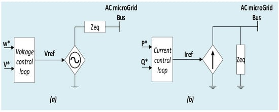
Figure 1.
Power converter classification: (a) grid-forming and (b) grid-following inverters.
GFM inverter control consists of a voltage control path that regulates the output voltage to a specified voltage reference and a phase-angle reference path that integrates a predetermined frequency to obtain the phase-angle reference. These references (voltage and frequency) are commonly achieved through decentralized control such as droop control [,], virtual synchronous machines [], virtual SG [], synchronverter [], power synchronization control [], generalized virtual synchronous control [], and virtual oscillator control []. Presently, the biggest challenges for decentralized control schemes are the seamless reconnection and black-start of GFM inverters [].
The decentralized control for GFM inverters is generally composed of inner control loops for current and voltage, a virtual impedance loop, and a controller employing a droop mechanism []. The primary control objectives for GFM inverters involve stabilizing amplitudes and ensuring power sharing among them. The stabilization of frequency and voltage is typically accomplished through current and voltage control loops, while the droop control mechanism facilitates power sharing [].
This paper is structured as follows: In Section 2, a comprehensive review of the GFM inverter control methods is carried out. Section 3 outlines the design methodology of an MG-based GFM inverter, including system description, modeling, voltage, and current loop control design. Section 4 explores GFM inverter frequency synchronization and restoration, emphasizing decentralized control using droop mechanisms. It introduces a new synchronization approach and examines frequency and voltage restoration during disturbances. Section 5 shows cases of the simulation results. A dedicated discussion is provided in Section 6. Finally, conclusions and future work are described in Section 7.
2. Related Work
The decentralized control design is very important for the GFM inverter’s performance. Various control approaches for GFM inverters are examined and compared with the GFM characteristics exhibited by synchronous machines in []. A hybrid grid-forming/following controller was proposed in []. Voltage synchronization is achieved by incorporating a phase-locked loop (PLL), and load sharing is facilitated through the utilization of a power-frequency droop. A droop-based GFM adaptive virtual resistance control was suggested in [] for postfault oscillation mitigation in GFM inverters. In [], authors investigated the use of impedance-based analysis to define, assess, and enhance the performance of GFM inverter controllers in various ways. In [], a multivariable controller was proposed with the aim of decoupling P and Q loops in GFM inverters using droop control and other methods. A decentralized control approach for multiparallel GFM-distributed generators on island MG was developed in []. It offers the advantage of decoupling the frequency from load conditions. The authors in [] explored GFM inverter modeling and control methodology, focusing on droop control. Embedding voltage and current loops within a single controller is a strategy that can significantly enhance the dynamic performance of the GFM system, as discussed in []. In MG’s with mismatched inductive/resistive feeder impedance, the virtual impedance loop, acting as an optional loop, plays a role in improving the power quality and power-sharing accuracy of GFM systems []. Drawbacks such as steady-state error and deviations in frequency and voltage amplitude are associated with the GFM droop control mechanism []. Consequently, a secondary control is introduced to mitigate these deviations []. Despite the deviations introduced by the total demand for active and reactive power from the loads, the GFM inverter system effectively restores both frequency and amplitude []. Additionally, a threshold-based method for frequency and voltage restoration in islanded MGs fed by droop-controlled GFM is proposed in []. It aims to restore the system when pulse load and plug-in events occur. A relevant solution for enhancing the efficiency and power quality of GFM inverters can be found in compact inverter structures, as demonstrated in [].
The primary focus of the above studies is on the dynamics of GFM microgrids. This focus intensifies specifically after a disturbance in the system when GFM inverters are operated in parallel. Less attention has been given to the synchronization and reconnection of GFM inverters in MG or the synchronization of GFM microgrids to the main grid. The main difficulty is the lack of information about voltage, frequency, and phase angle at the PCC. Hence, the synchronization with other sources and proportional contribution to power-sharing in the (V-f) mode becomes challenging tasks for the incoming inverter. Likewise, when transitioning from islanded operation to grid-connected mode, the synchronization of the MG with the main grid is a necessary step. Thus, a synchronization control algorithm is necessary. A seamless connection to the MG/grid is essential for both GFM and grid-following inverters. A synchronization method for inverters in GFM, known as the controller-sync, is proposed in []. In this approach, the inverter initially aligns with the MG frequency without contributing to power sharing. Subsequently, the controller transitions to power-sharing mode. A communication-based method to synchronize the GFM microgrid to the utility grid is proposed in []. This approach is based on exchanging data between two proposed devices: synchronization data sender and a synchronization data controller.
In summary, the current state of research reveals certain gaps:
- The comprehensive applicability of droop-based control in GFM inverters remains inadequately addressed.
- The analysis of the decentralized control’s performance is lacking, particularly in the context of off-grid systems and varying PQ load demands.
Furthermore, when it comes to synchronization techniques, several gaps exist:
- While many techniques address the connection of inverters to the utility grid, there is a lack of exploration regarding the (re)connection of an inverter to an islanded MG.
- The majority of techniques are designed for inverters operating in (P-Q) control mode, leaving a gap in the understanding of inverters in (V-f) control mode post-(re)connection.
- Certain methods require communication infrastructure, leading to cost implications for the seamless plug-and-play operation of inverters and exposing them to potential cyber-attacks.
This paper provides a comprehensive examination of the theoretical analysis of GFM inverters and their control structures. It validates the assumed and resulting P-f and Q-V droop characteristics utilized to drive GFM inverters. The verification process includes assessing the power-sharing concept and demonstrating its effectiveness by connecting two GFM inverters to meet varying load demands. The study also addresses the seamless connection or reconnection of an inverter to an islanded MG in GFM mode. Additionally, the paper proposes a synchronization loop designed to maintain the system in GFM mode even after synchronization is established.
3. Methodology
3.1. System Description and Modeling
Usually, GFM inverter-based MG consists of VSIs, which can operate in stand-alone and grid-connected modes of operation. VSIs stand as an interface between distributed energy sources and loads; their main role is to convert the DC power into AC power and supply the entire MG. The VSIs are controlled by the pulse width modulation (PWM) signals, which generate harmonic components that decrease the power quality. Thus, filters are required to mitigate harmonics and avoid disturbances caused by them. Considering the voltage harmonic limitations defined in [], the use of an LCL filter is considered to be a good compromise in terms of high-frequency harmonic mitigation and passive element design []. The LCL topology is adopted in this work, as can be seen in Figure 2. The inverter is associated with the LCL filter to form the VSI.

Figure 2.
Three-phase inverter single-line diagram interfaced using an LCL filter.
The mathematical model of the VSI in the dq reference frame can be summarized by the following equations:
3.1.1. Voltage and Current Loops
For the voltage and current controllers, a cascade loop has been used; the current loop must have the fastest response time and, hence the highest bandwidth. The voltage loop must be slower than the current loop, and it must be quick enough to guarantee that the system is properly operated. PI controllers have been employed by both regulators. This choice has been made due to the straightforward design of the PI controller gains and the simplicity of system modeling in the dq reference frame.
The state space representation of the current loop is described as follows:
The terms and in Equation (1) represent a coupling between the two equations and . In other words, a variation of the current will create a variation of the current and vice-versa.
The state space representation of the voltage loop is as follows:
3.1.2. Inner Loops Control Design
The objective of any control system is to shape the response of the system according to a given reference. It also aims to maintain the stability of the system in a closed loop with the desired performance while minimizing the effect of disturbances and measurement noise and avoiding the saturation of controllers, despite the uncertainties of modeling, variations of parameters, or changes in the operating point.
The control diagram used for the GFM-MG in Figure 3 consists of an external voltage loop and an internal current loop that provides the current reference and control signal, respectively. This type of control is called multi-loop control or cascaded loop control. It is usually chosen for current and voltage control of GFM inverters due to its superior disturbance rejection performance and current-limiting capability [].
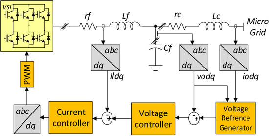
Figure 3.
Inner loops (voltage and current controllers).
When using the GFM configuration, the voltage and frequency references are offered by the local controller, such as droop control.
Current Loop Controller Design
The current control loop is responsible for the characteristics of the injected current. It is highly desirable that the inverter current be free of low-order harmonics. High-frequency harmonics can be eliminated with the LCL filter. Current control for the inner loop is implemented using standard feedback control. The current control can be expressed by the following system of equations:
where:
- and are the d- and q-axis components of the voltage modulation signals, respectively.
- and are the values of the inductance current for the d- and q-axis components, respectively.
- and are the proportional and integral PI regulator parameters for current control and represents the inductance of the inverter-side filter.
Figure 4 shows the detailed diagram of the current control loop. It should be noted that all the current control loops, all signals in the loop feedforward, and the feedback loops are direct quantities [].
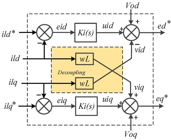
Figure 4.
Block diagram of current controller loops.
The transfer function of the d component of the current loop is identified by:
To decouple the dynamics of the loops, the internal loop (current loop) must be designed to have faster dynamics compared to the outer loop (voltage loop).
From Figure 4, it can be concluded that the two current control loops of the two d- and q-axes are similar. Thus, the corresponding controllers can also be identical. Since the switching frequency is significantly higher than the line frequency, sample delays can be neglected in controller design [].
The transfer function of the current PI regulator is:
From the block diagram in Figure 5, the closed loop transfer function for the current loop is as follows:
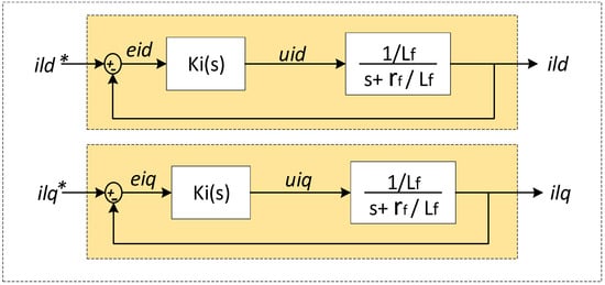
Figure 5.
Block diagram of the closed-loop control for current.
By assimilating the equation above with the quadratic characteristic equation, the damping factor and the natural oscillation frequency can be obtained as follows:
Hence, the parameters of the current regulator can be designed as follows:
According to the theory of optimal techniques and are based on the time domain specification. Usually, the natural frequency is selected as , with is the switching angular frequency.
Voltage Loop Controller Design
Voltage regulation is required to inject good-quality energy. The external voltage control loop is developed using the standard feedback/feedforward control, which commonly uses a PI controller. The voltage control can be expressed as:
where
- and are the d- and q-axis inductance current references, respectively;
- and are the voltage references;
- is the angular frequency, and are the proportional and integral parameters of the PI regulator. For voltage control, represents the capacitance of the filter and is the feedforward current gain. Figure 6 shows the block diagram of the voltage control loop.
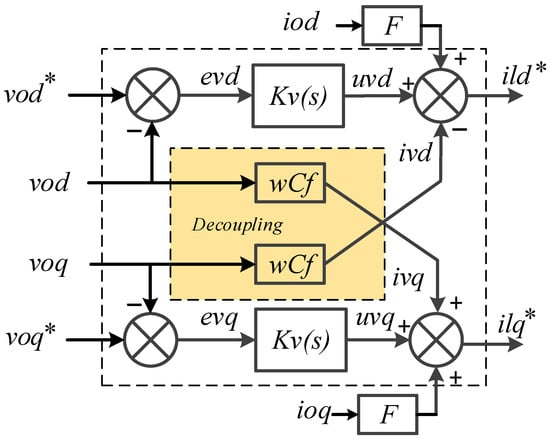
Figure 6.
Block diagram of voltage controller loops.
The transfer function of the voltage loop in the d-axis is:
The transfer function of the voltage PI regulator is:
From the block diagram in Figure 7, the closed-loop transfer function of the voltage loop is as follows:
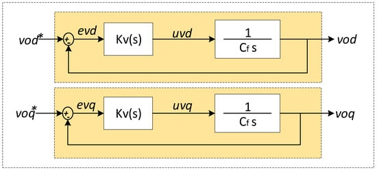
Figure 7.
Block diagram of closed-loop control for voltage.
Like the process of designing the current loop controller, the damping factor and the natural oscillation frequency of the voltage loop can be obtained as follows:
Hence, the voltage regulator parameters can be designed as follows:
is chosen equal to 0.707 and is chosen as /500.
4. Grid-Forming Inverters Frequency Synchronization and Restoration
4.1. Droop Control and Virtual Impedance
In order to equally share the power between the GFM inverters and to ensure the power flow, the reference of the voltage control loop vref is provided by the decentralized control that comprises the droop controller and the virtual impedance loop. The amplitude and phase of the voltage reference are generated by the droop control according to the measured active and reactive powers. The droop functions can be expressed as follows []:
where and are the nominal frequency and voltage references, and are the droop coefficients for the frequency and the voltage, respectively. Notice that the d-axis is aligned with the phase A voltage in a three-phase system, thus the q-component is equal to zero.
The droop coefficients and can be selected based on the following equations:
Being, and are the maximum frequency and voltage amplitude deviations, respectively. Parameters and are the rated active and reactive powers, respectively. The averaged power can be calculated through a low-pass filter to attenuate the high-frequency noises as follows:
A virtual impedance loop has been added to the decentralized control to improve the current sharing between the GFM inverters by fixing and normalizing the output impedance of the GFM inverters, which will determine the P/Q power angle/amplitude relationship (inductive droop), thus, avoiding using additional physical inductors/resistors. Figure 8 shows the additional block of the virtual impedance loop; the output impedance of the VSI must be sufficiently inductive. Thus, the additional block of the virtual impedance loop can be expressed as shown below []:
where and are the virtual resistance and inductance value and are the virtual voltage compensation and output current in dq—reference frame, respectively. The closed-loop modeling and the stability analysis of the virtual impedance loop have been studied in previous works [,], and will not be addressed here.
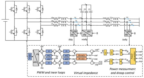
Figure 8.
Block diagram of grid-forming inverter controller.
4.2. Proposed Synchronization Loop
Before connecting the incoming GFM inverter to the MG, it must be synchronized with the MG, and then the circuit breaker is closed for power sharing. Similarly, to connect the MG to the utility grid for grid-connected operation, a synchronization process is required. The synchronization process provides a seamless connection, which mitigates the current fluctuations and maintains the system’s stability. The synchronization is achieved through the proposed synchronization control loop in a synchronous dq reference frame, as presented in Figure 9.
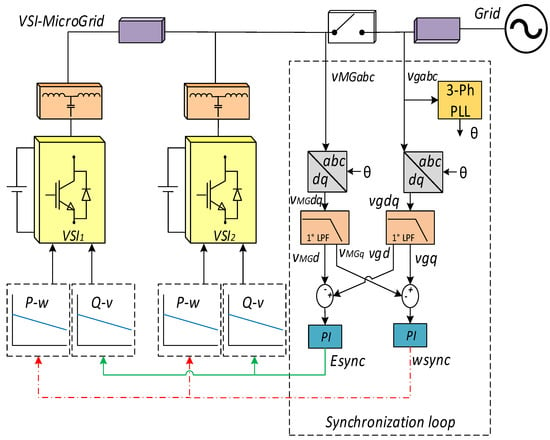
Figure 9.
Block diagram of the synchronization control loop for GFM-based MG.
The main difference between the state-of-the-art synchronization approaches and the proposed one is that the controller in those approaches switches from GFM mode to grid-following mode after connection to the PCC, causing the inverter to lose control over the voltage magnitude and frequency. Indeed, in the proposed approach, the inverter operates in GFM mode even after the synchronization has occurred.
When scheduling grid-connected mode operation, synchronization is released by utilizing the direct and quadrature voltage components Vdqg and VdqMG of both the grid and the MG, respectively. These components are acquired through the Park transformation, employing the phase angle provided by the phase-locked loop (PLL). A comparison between the direct and quadrature components of both MG and the main grid voltages produces signal errors, which serve as input for the proportional-integral (PI) regulators. The PI controllers generate correction signals, Esync and sync, to ensure proper synchronization. Similarly, for connecting an incoming VSI to the MG, the direct and quadrature voltage components of the MG and the incoming VSI are used. The synchronization is achieved when the voltage components are equal: VdMG = Vdg and VqMG = Vqg (MG and grid synchronization). To achieve this, a synchronization structure is required.
The synchronization structure includes a three-phase PLL, a low pass filter and a PI controller for both direct and quadrature axes as follows:
where and are the PI parameters, which are the same for both axes and is the filter cut-off frequency. and are the synchronization controller output signals to be added for the droop controller functions P-w and Q-v, respectively at each VSI to synchronize itself. Notice that the three-phase PLL is used to extract the phase angle of the utility grid that is used after to transform both grid and MG voltages from the abc reference frame to the dq reference frame.
4.3. Frequency and Voltage Restoration
The secondary control is introduced to compensate for the steady-state error caused by the droop control deviations after load connection to meet the grid standard. In this work, a centralized topology is adopted to allow the GFM inverters to compensate for the frequency and voltage set points, as expressed as follows []:
where , , , and are the control gains of the secondary control regulators. Notice that the output must be saturated to avoid exceeding the maximum and minimal limits of the voltage and frequency drops.
The entire GFM control system, including inner loops, virtual impedance, droop control, and secondary control, is depicted in Figure 10.
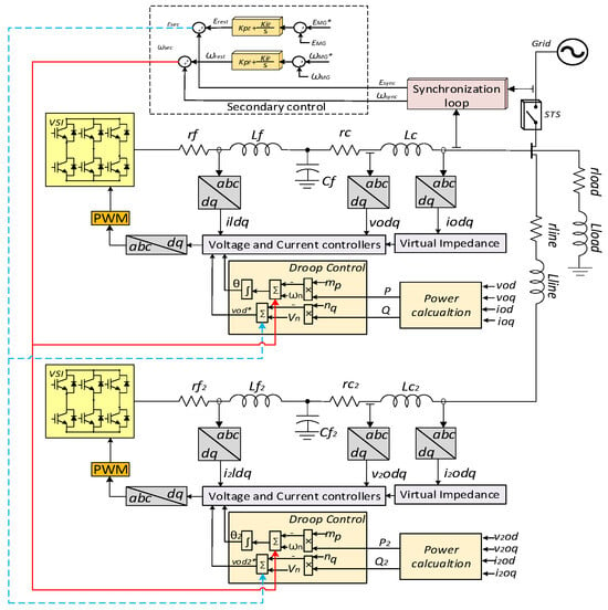
Figure 10.
Block diagram of the entire control system of the MG.
4.3.1. Frequency Restoration
To design the frequency restoration controller gains and to ensure system stability, the model depicted in Figure 11 is used. It consists of three main blocsk; the droop control block to determine the MG frequency, a reduced first-order PLL model to measure the MG frequency, and the secondary control compensator Gfsec(s) associated with a delay transfer function Gd(s) to mimic the communication line delay. From the developed model in Figure 10, the transfer function can be obtained as follows:
where the transfer function of each bloc is as follows:
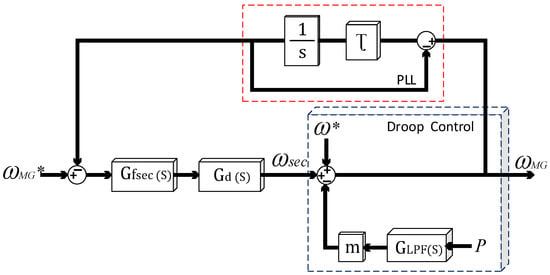
Figure 11.
Block diagram of the frequency restoration control.
Consequently, the closed loop transfer function P to can be obtained as follows:
With the following parameters:
Figure 12 depicts the step response of the model in (29) for a P step change. This model allows us to properly adjust the control parameters of the secondary control and study the limitations of the communications delay.
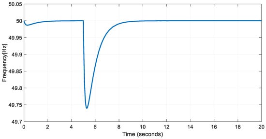
Figure 12.
Example of transient response for frequency restoration.
4.3.2. Amplitude Restoration
A similar method has been followed to adjust the voltage secondary controller parameters. The obtained block diagram, in this case, is depicted in Figure 13.
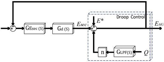
Figure 13.
Block diagram of the amplitude restoration control.
By the same procedure, the closed loop voltage dynamic model is as follows:
Being is the voltage compensator.
Thus, the closed-loop transfer function of the voltage secondary controller from Q to can be expressed as follows:
By using this model, the dynamics of the system for a step change in Q can be obtained, as shown in Figure 14.
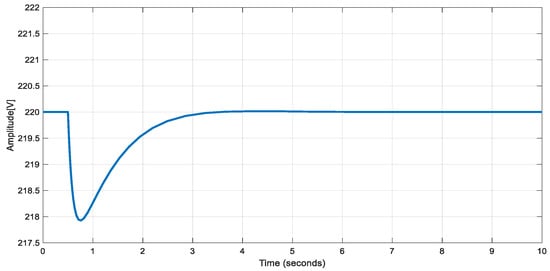
Figure 14.
Transient response for amplitude restoration.
5. Simulation Results
To implement and test the feasibility of the theoretical analysis developed above, a GFM inverters-based MG model was built in Matlab-Simulink, as illustrated in Figure 10. The used parameters are listed in Table A1 in Appendix A. The MG model consists of two VSIs interfaced using an LCL filter and connected to each other through a line. These GFM inverters supply a local load.
5.1. Voltage and Current Waveforms
Figure 15 and Figure 16 illustrate the voltage and output current waveforms of the GFM inverters supplying a local load. Figure 16 further depicts the dynamic response of the voltage and current loops in the dq reference frame for both axes. Notably, the voltage controller achieves a settling time of 0.005 s while maintaining a steady-state error at its minimum of 0.1 V. Similarly, the current controller ensures a settling time of 0.006 s with a steady-state error of 10−5.
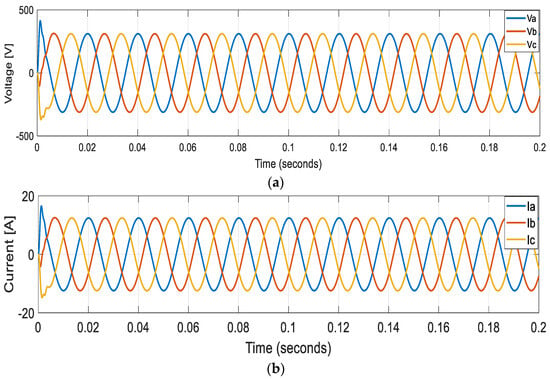
Figure 15.
Grid-forming controlled inverter (a) output voltage and (b) current waveforms.
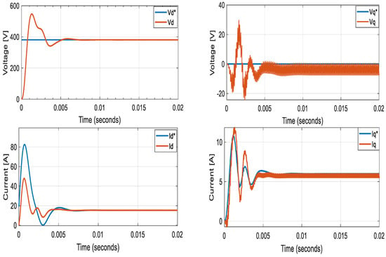
Figure 16.
Inner loops voltage and current d- and q-axes components.
Figure 17 illustrates the output currents of the two-paralleled GFM inverters controlled using droop control in stand-alone mode. Initially, both inverters shared the load equally. At t = 1 s, the second inverter is disconnected, and the remaining inverter continues to supply the load, ensuring uninterrupted power supply even if one inverter is tripped. This test shows the robustness of droop control in power-sharing among inverters without the need for communication, thereby enhancing system reliability.
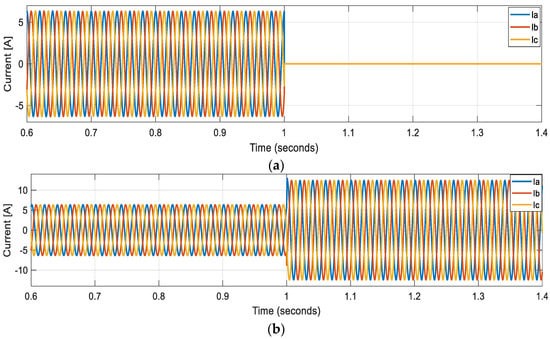
Figure 17.
Transient response of the output currents (a) VSI1 (b) VSI2, when the VSI 1 is disconnected at t = 1 s.
In Figure 18, the spectrum of the voltage at the PCC is presented. The system employing the proposed controller demonstrates a low total harmonic distortion (THD) of 1.46%, indicative of improved power quality of the output voltage.
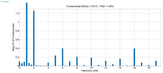
Figure 18.
Spectrum of the voltage at the point of common coupling.
5.2. Inverters Synchronization to the MG
The process of connecting an incoming GFM inverter into the MG involves a crucial synchronization step to ensure seamless integration, as depicted in Figure 19. Based on the proposed synchronization approach, Figure 19a illustrates the synchronization process by displaying the frequency profiles of both the MG and the incoming GFM inverter. At t = 0.5 s, the synchronization process is initiated. During this phase, the incoming inverter undergoes adjustments to match its frequency and its phase with that of the MG. These adjustments can lead to temporary frequency fluctuations in the incoming GFM inverter. These fluctuations are part of the synchronization procedure, and they are carefully managed to minimize any disruption to the MG’s operation. The critical moment arrives at t = 2 s when synchronization is successfully achieved. At this point, the incoming inverter’s frequency is perfectly aligned with that of the MG. Thus, the incoming GFM inverter can be safely connected to the MG. Upon connection, the incoming inverter immediately begins sharing active power within the MG, as can be seen in Figure 19b. This synchronization and subsequent power-sharing ensure that the MG is efficiently operating, maintaining stable frequency, and efficiently distributing electrical power to meet the connected loads power demand.
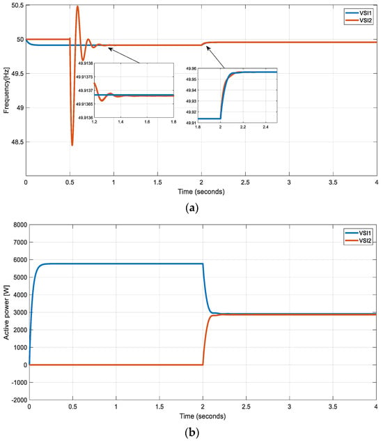
Figure 19.
Synchronization process of inverters (a) frequency of two sides (b) Active power sharing between the two GFM inverters.
5.3. Freaquency and Voltage Restoration Performance
This test demonstrates how the secondary control restores the voltage and frequency of the GFM-MG to switch to grid-connected mode. As can be seen in Figure 20a, the secondary control is activated at t = 0.5 s and the system starts recovering the frequency to its nominal value. After that the system subjected load changes at t = 2 s and t = 4 s. It can be noticed that the secondary control acted for both sudden changes and eliminated the deviation. Similarly, when the inverter two is disconnected at t = 6 s, the secondary control is quickly acted, and the frequency is kept at its set point after 2 s. It is clear from Figure 20b that the active power sharing among GFM inverters was not affected by the action of the secondary control.
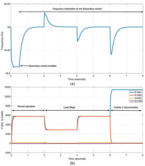
Figure 20.
Simulation results during load step changes (t = 2 s and t = 4 s) and sudden disconnection of inverter 2 (t = 6 s): (a) Frequency restoration (b) Active and reactive powers.
5.4. Impact of Communication Time Delays
Communication infrastructures play a critical role in GFM-MG operation by providing and exchanging the data between the MG central controller (MGCC)and the DG units local controllers. In secondary control, the voltage and frequency correction signals are sent using the MGCC through a low-bandwidth communication infrastructure to restore the deviations caused by the primary control. For this, the communication delay effect on the secondary control has been investigated for different time delay amounts. Figure 21 shows the voltage and frequency during the restoration process. It is clear that the communication delays cause oscillations in both voltage and frequency, and the increase of the time delay results in high oscillations up to 300 ms where the system stability becomes threatened.
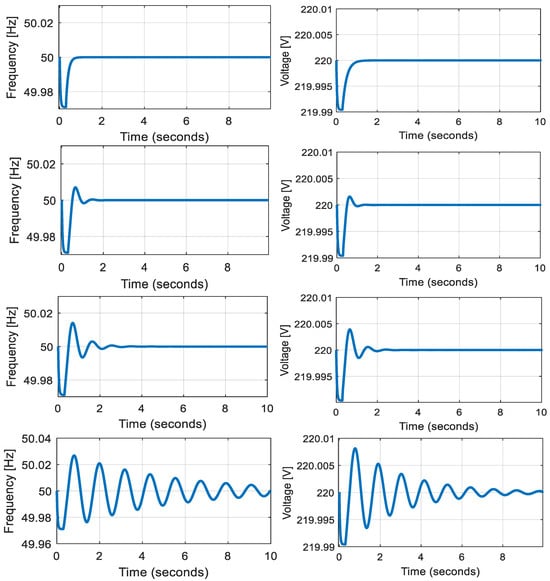
Figure 21.
Secondary frequency dynamics under different communication delays (from top to bottom 150 ms until 300 ms).
5.5. Synchronization with the Main Grid
Synchronization is necessary for the transition from islanded mode to grid-connected mode to avoid high current fluctuations and equipment damage. The synchronization process between the DG unit and the main grid is illustrated in Figure 22a,b. As can be seen at the start of the synchronization the voltage waveforms are not synchronized yet and the voltage difference between the MG and the grid is high, during the synchronization process the voltage waveforms started becoming closer to each other as shown by Figure 22b and the voltage difference starts decreasing as depicted in Figure 22a. At the end of the synchronization process, the voltage waveforms are matched and the voltage error value is decreased to zero, which ensures a seamless transition mode. It is worth to notice that the synchronization process has no impact on the system stability since the bandwidth is much more reduced.
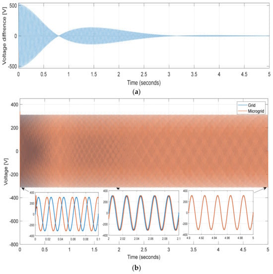
Figure 22.
Synchronization process (a) voltage difference (b) Grid and MG voltages.
6. Discussion
The simulation results provide a comprehensive overview of the proposed control strategies’ effectiveness. The GFM inverter exhibits a low total harmonic distortion (THD) of 1.46%, enhancing the power quality of the output voltage. In stand-alone mode, two paralleled GFM inverters controlled with droop control share the load seamlessly, demonstrating the system’s reliability. The synchronization process is crucial for integrating an incoming inverter into the MG. It ensures the successful alignment of the frequency and phase, facilitating a smooth connection. Moreover, secondary control is proved to be vital in restoring MG voltage and frequency, efficiently managing load changes and inverters disconnection. Communication delays are identified as potential sources of voltage and frequency oscillations, threatening system stability. Lastly, the synchronization between the Distributed Generation (DG) unit and the main grid illustrates a gradual and stable transition from islanded to grid-connected mode. Overall, the proposed control strategies exhibit robust performance, ensuring stability and efficiency across diverse operating scenarios. Table 1 summarizes the main simulation results of the proposed control approach for frequency synchronization and amplitude restoration. However, the proposed control approach exhibit some limitations, notably a substantial frequency drop during the synchronization process, increasing the synchronization time. Additionally, the dynamic behavior of the voltage and current loops, assuming they are faster than the outer loop, is proven to be accurate for high-bandwidth power converters in low-power applications like MG and UPS. Nevertheless, in high-power scenarios such as transmission systems, the control bandwidth constraints imposed by the switching frequency can result in delayed responses, decreased stability regions, and potential instability issues in grid-connected mode, as detailed in our analysis. Addressing and mitigating these limitations will be a priority for future works.

Table 1.
Simulation results: Time domain and steady-state specifications of the proposed control diagram.
7. Conclusions
This paper focused on the modeling, analysis, and design of GFM inverters within a MG. The islanded operation of GFM inverters is investigated. The droop control is adopted as a decentralized method, and a secondary control for frequency and voltage restoration is developed as centralized control loops. Moreover, this paper proposes a synchronization loop to connect incoming inverters to the MG. The successful application of this decentralized approach highlights the feasibility and accuracy of deploying GFM inverters in the distribution network without the need for communication. The simulation results highlight the robustness and efficiency of the implemented control strategies. The voltage controller, ensuring an impressive settling time of 0.005 s, maintains a minimal steady-state error of 0.1 V. Similarly, the current controller exhibits efficient dynamics, achieving a settling time of 0.006 s and a low steady-state error of 10−5. The designed controller contributes to the system’s overall quality by minimizing total harmonic distortion (THD) to 1.46%, thereby enhancing the power quality of the output voltage. Moreover, the system displays interesting resilience during dynamic load conditions and tripping events, demonstrating a quick restoration time of 1 s with a minimal steady-state error of 10−10. The synchronization process further validates the system’s reliability, with incoming inverters achieving synchronization in just 0.8 s. The MG synchronization with the main grid is accomplished in 3 s, maintaining a steady-state error ratio of 10−9. These simulation results not only confirm the accuracy of the assumed droop settings but also shows the responsive droop behavior to PQ load variations. The droop control methodology effectively meets load demand with precision, ensuring equitable power sharing between GFM inverters. Additionally, the proposed synchronization loop facilitates a seamless transition for incoming inverters without the need for communication between power generation units. This integrated approach demonstrates the potential for practical implementation, offering a reliable and efficient solution for MG operation with enhanced stability, power quality, and synchronization capabilities. Thus, these methods provide decentralized power sharing and avoid transients and undesired dynamics in the MG.
Future research possibilities include examining GFM inverters at distribution and transmission levels, addressing aspects such as hardware implementation, energy storage, system protection, fault ride-through capability, stability analysis, and economic dispatching. Furthermore, exploring the intricate dynamics between a GFM inverter and multiple grid-following inverters within a MG offers an additional avenue for future investigations.
Author Contributions
Conceptualization, I.B., E.E., A.H., Y.D., A.S., A.E.M.B. and B.K.; methodology, I.B., E.E., A.H., Y.D., A.S., A.E.M.B. and B.K.; software, I.B., E.E., A.H. and Y.D.; validation, I.B., E.E., A.H., Y.D., A.S., A.E.M.B. and B.K.; formal analysis, I.B., E.E., A.H., Y.D., A.S., A.E.M.B. and B.K.; investigation, I.B., E.E., A.H., Y.D., A.S., A.E.M.B. and B.K.; resources, I.B., E.E., A.H. and Y.D.; data curation, I.B.; writing—original draft preparation, I.B.; writing—review and editing, E.E., A.H., Y.D., A.S., A.E.M.B. and B.K.; supervision, E.E., A.H., Y.D., A.S. and A.E.M.B.; funding acquisition, E.E., A.H. and Y.D. All authors have read and agreed to the published version of the manuscript.
Funding
This research received no external funding.
Data Availability Statement
Data are contained within the article.
Conflicts of Interest
The authors declare no conflict of interest.
Abbreviations
The following abbreviations are used in this manuscript:
| GFM | Grid-forming |
| MG | Microgrid |
| VSI | Voltage source inverters |
| SG | Synchronous generators |
| DG | Distributed generation |
| PLL | Phase-locked loop |
| THD | Total harmonic distortion |
| PWM | Pulse width modulation |
| PCC | Point of common coupling |
| MGCC | Microgrid central controller |
| UPS | Uninterruptible power supply |
Appendix A

Table A1.
Microgrid parameters.
Table A1.
Microgrid parameters.
| Inverter Parameters (10 kVA Rating) | |||
|---|---|---|---|
| Parameter | Value | Parameter | Value |
| fs | 8 kHz | Cf | 50 uF |
| Lf | 1.35 mH | rf | 0.1 Ω |
| Lc | 0.35 mH | rc | 0.03 Ω |
| Line and Load parameters | |||
| rline | 0.1 Ω | rload | 25 Ω |
| Lline | 0.35 mH | Lload | 10−5 mH |
| Primary control parameters | |||
| mp | 9.4 × 10⁻⁵ (=0.3% droop) | nq | 1.3 × 10⁻³ (=2% droop) |
| Wn | 314.16 rad/s | Vn | 311 V |
| Wc | 31.41 rad/s | ||
| Rv | 0.0370 | Lv | 0.0200 |
| Voltage and current Controller parameters | |||
| Voltage controller | Current controller | ||
| Kpv | 0.037 | Kiv | 393 |
| Kpc | 10.5 | Kic | 16 × 103 |
| F | 0.75 | ||
| Secondary control | |||
| KpE | 0.2 | KiE | 0.05 |
| KpF | 0.01 | KiF | 5 |
| τ | 50 ms | ||
References
- Gursoy, M.; Mirafzal, B. Direct vs. Indirect control schemes for grid-forming inverters–unveiling a performance comparison in a microgrid. IEEE Access 2023, 11, 75023–75036. [Google Scholar] [CrossRef]
- Guerrero, J.M.; Vasquez, J.C.; Matas, J.; De Vicuña, L.G.; Castilla, M. Hierarchical control of droop-controlled AC and DC microgrids—A general approach toward standardization. IEEE Trans. Ind. Electron. 2010, 58, 158–172. [Google Scholar] [CrossRef]
- Issa, W.; Al-Naemi, F.; Konstantopoulos, G.; Sharkh, S.; Abusara, M. Stability analysis and control of a microgrid against circulating power between parallel inverters. Energy Procedia 2019, 157, 1061–1070. [Google Scholar] [CrossRef]
- Alsiraji, H.A.; Guerrero, J.M. A new hybrid virtual synchronous machine control structure combined with voltage source converters in islanded ac microgrids. Electr. Power Syst. Res. 2021, 193, 106976. [Google Scholar] [CrossRef]
- Bevrani, H.; Ise, T.; Miura, Y. Virtual synchronous generators: A survey and new perspectives. Int. J. Electr. Power Energy Syst. 2014, 54, 244–254. [Google Scholar] [CrossRef]
- Shuai, Z.; Hu, Y.; Peng, Y.; Tu, C.; Shen, Z.J. Dynamic stability analysis of synchronverter-dominated microgrid based on bifurcation theory. IEEE Trans. Ind. Electron. 2017, 64, 7467–7477. [Google Scholar] [CrossRef]
- Wu, H.; Wang, X. Design-oriented transient stability analysis of grid-connected converters with power synchronization control. IEEE Trans. Ind. Electron. 2018, 66, 6473–6482. [Google Scholar] [CrossRef]
- Rathnayake, D.B.; Razzaghi, R.; Bahrani, B. Generalized virtual synchronous generator control design for renewable power systems. IEEE Trans. Sustain. Energy 2022, 13, 1021–1036. [Google Scholar] [CrossRef]
- Gurugubelli, V.; Ghosh, A.; Panda, A.K. Design and implementation of optimized virtual oscillatory controllers for grid-forming inverters. ISA Trans. 2023, 139, 685–712. [Google Scholar] [CrossRef]
- Unruh, P.; Nuschke, M.; Strauß, P.; Welck, F. Overview on grid-forming inverter control methods. Energies 2020, 13, 2589. [Google Scholar] [CrossRef]
- Rathnayake, D.B.; Akrami, M.; Phurailatpam, C.; Me, S.P.; Hadavi, S.; Jayasinghe, G.; Zabihi, S.; Bahrani, B. Grid forming inverter modeling, control, and applications. IEEE Access 2021, 9, 114781–114807. [Google Scholar] [CrossRef]
- Guerrero, J.M.; Matas, J.; Garcia De Vicunagarcia De Vicuna, L.; Castilla, M.; Miret, J. Wireless-Control Strategy for Parallel Operation of Distributed-Generation Inverters. IEEE Trans. Ind. Electron. 2006, 53, 1461–1470. [Google Scholar] [CrossRef]
- Anttila, S.; Döhler, J.S.; Oliveira, J.G.; Boström, C. Grid forming inverters: A review of the state of the art of key elements for microgrid operation. Energies 2022, 15, 5517. [Google Scholar] [CrossRef]
- Geng, S.; Hiskens, I.A. Unified grid-forming/following inverter control. IEEE Open Access J. Power Energy 2022, 9, 489–500. [Google Scholar] [CrossRef]
- Me, S.P.; Zabihi, S.; Blaabjerg, F.; Bahrani, B. Adaptive Virtual Resistance for Postfault Oscillation Damping in Grid-Forming Inverters. IEEE Trans. Power Electron. 2022, 37, 3813–3824. [Google Scholar] [CrossRef]
- Ray, I. Review of impedance-based analysis methods applied to grid-forming inverters in inverter-dominated grids. Energies 2021, 14, 2686. [Google Scholar] [CrossRef]
- Rathnayake, D.B.; Bahrani, B. Multivariable control design for grid-forming inverters with decoupled active and reactive power loops. IEEE Trans. Power Electron. 2022, 38, 1635–1649. [Google Scholar] [CrossRef]
- Huang, X.; Wang, K.; Qiu, J.; Hang, L.; Li, G.; Wang, X. Decentralized control of multi-parallel grid-forming DGs in islanded microgrids for enhanced transient performance. IEEE Access 2019, 7, 17958–17968. [Google Scholar] [CrossRef]
- Salem, Q.; Aljarrah, R.; Karimi, M.; Al-Quraan, A. Grid-Forming Inverter Control for Power Sharing in Microgrids Based on P/f and Q/V Droop Characteristics. Sustainability 2023, 15, 11712. [Google Scholar] [CrossRef]
- Dragičević, T. Model predictive control of power converters for robust and fast operation of AC microgrids. IEEE Trans. Power Electron. 2017, 33, 6304–6317. [Google Scholar] [CrossRef]
- Wang, X.; Li, Y.W.; Blaabjerg, F.; Loh, P.C. Virtual-impedance-based control for voltage-source and current-source converters. IEEE Trans. Power Electron. 2014, 30, 7019–7037. [Google Scholar] [CrossRef]
- Bennia, I.; Daili, Y.; Harrag, A. Hierarchical Control of Paralleled Voltage Source Inverters in Islanded Single Phase Microgrids. In Proceedings of the International Conference in Artificial Intelligence in Renewable Energetic Systems, Tipaza, Algeria, 22–24 November 2020; Springer: Berlin/Heidelberg, Germany, 2020; pp. 302–313. [Google Scholar]
- Bekker, I.; Hofmann, L.; Mertens, A. Secondary control with grid-forming inverters for an island grid restoration approach without communication. Electr. Power Syst. Res. 2022, 213, 108498. [Google Scholar] [CrossRef]
- Bennia, I.; Harrag, A.; Daili, Y.; Bouzid, A.; Guerrero, J.M. Decentralized secondary control for frequency regulation based on fuzzy logic control in islanded microgrid. Indones. J. Electr. Eng. Comput. Sci. 2023, 29, 85–100. [Google Scholar] [CrossRef]
- Sadeque, F.; Mirafzal, B. Frequency restoration of grid-forming inverters in pulse load and plug-in events. IEEE J. Emerg. Sel. Top. Ind. Electron. 2022, 4, 580–588. [Google Scholar] [CrossRef]
- Aouichak, I.; Jacques, S.; Bissey, S.; Reymond, C.; Besson, T.; Le Bunetel, J.-C. A bidirectional grid-connected DC–AC converter for autonomous and intelligent electricity storage in the residential sector. Energies 2022, 15, 1194. [Google Scholar] [CrossRef]
- Sharma, D.; Sadeque, F.; Mirafzal, B. Synchronization of inverters in grid forming mode. IEEE Access 2022, 10, 41341–41351. [Google Scholar] [CrossRef]
- Litwin, M.; Zieliński, D.; Gopakumar, K. Remote micro-grid synchronization without measurements at the point of common coupling. IEEE Access 2020, 8, 212753–212764. [Google Scholar] [CrossRef]
- Llaria, A.; Curea, O.; Jiménez, J.; Camblong, H. Survey on microgrids: Unplanned islanding and related inverter control techniques. Renew. Energy 2011, 36, 2052–2061. [Google Scholar] [CrossRef]
- Bennia, I.; Daili, Y.; Harrag, A. LCL Filter Design for Low Voltage-Source Inverter. In Proceedings of the International Conference on Artificial Intelligence in Renewable Energetic Systems, Tipasa, Algeria, 22–24 November 2021; Springer: Berlin/Heidelberg, Germany, 2021; pp. 332–341. [Google Scholar] [CrossRef]
- Loh, P.C.; Holmes, D.G. Analysis of multiloop control strategies for LC/CL/LCL-filtered voltage-source and current-source inverters. IEEE Trans. Ind. Appl. 2005, 41, 644–654. [Google Scholar] [CrossRef]
- Haddadi, A.; Boulet, B.; Yazdani, A.; Joós, G. A μ-based approach to small-signal stability analysis of an interconnected distributed energy resource unit and load. IEEE Trans. Power Deliv. 2014, 30, 1715–1726. [Google Scholar] [CrossRef]
- Issa, W.R. Improved Control Strategies for Droop-Controlled Inverter-Based Microgrid. Master’s Thesis, University of Exeter, Exter, UK, 2015. [Google Scholar] [CrossRef]
- Pogaku, N.; Prodanovic, M.; Green, T.C. Modeling, Analysis and Testing of Autonomous Operation of an Inverter-Based Microgrid. IEEE Trans. Power Electron. 2007, 22, 613–625. [Google Scholar] [CrossRef]
- Vasquez, J.C.; Guerrero, J.M.; Savaghebi, M.; Eloy-Garcia, J.; Teodorescu, R. Modeling, analysis, and design of stationary-reference-frame droop-controlled parallel three-phase voltage source inverters. IEEE Trans. Ind. Electron. 2012, 60, 1271–1280. [Google Scholar] [CrossRef]
- Erdocia, J.; Urtasun, A.; Marroyo, L. Power Angle–Frequency Droop Control to Enhance Transient Stability of Grid–Forming Inverters under Voltage Dips. IEEE J. Emerg. Sel. Top. Power Electron. 2022, 11, 3751–3764. [Google Scholar] [CrossRef]
- Qoria, T.; Gruson, F.; Colas, F.; Guillaud, X.; Debry, M.-S.; Prevost, T. Tuning of cascaded controllers for robust grid-forming voltage source converter. In Proceedings of the 2018 Power Systems Computation Conference (PSCC), Dublin, Ireland, 11–15 June 2018; IEEE: Piscataway, NJ, USA, 2018; pp. 1–7. [Google Scholar]
- Khayat, Y.; Shafiee, Q.; Heydari, R.; Naderi, M.; Dragičević, T.; Simpson-Porco, J.W.; Dörfler, F.; Fathi, M.; Blaabjerg, F.; Guerrero, J.M. On the secondary control architectures of AC microgrids: An overview. IEEE Trans. Power Electron. 2019, 35, 6482–6500. [Google Scholar] [CrossRef]
Disclaimer/Publisher’s Note: The statements, opinions and data contained in all publications are solely those of the individual author(s) and contributor(s) and not of MDPI and/or the editor(s). MDPI and/or the editor(s) disclaim responsibility for any injury to people or property resulting from any ideas, methods, instructions or products referred to in the content. |
© 2023 by the authors. Licensee MDPI, Basel, Switzerland. This article is an open access article distributed under the terms and conditions of the Creative Commons Attribution (CC BY) license (https://creativecommons.org/licenses/by/4.0/).